Force F-G20-BASE User manual

OWNER’S MANUAL F-G20
CAUTION!
Read all precautions and instructions in this manual before using this equipment.
OWNER’S MANUAL F-G20-BASE
CAUTION!
Read all precautions and instructions in this manual before using this equipment.

Table of Contents
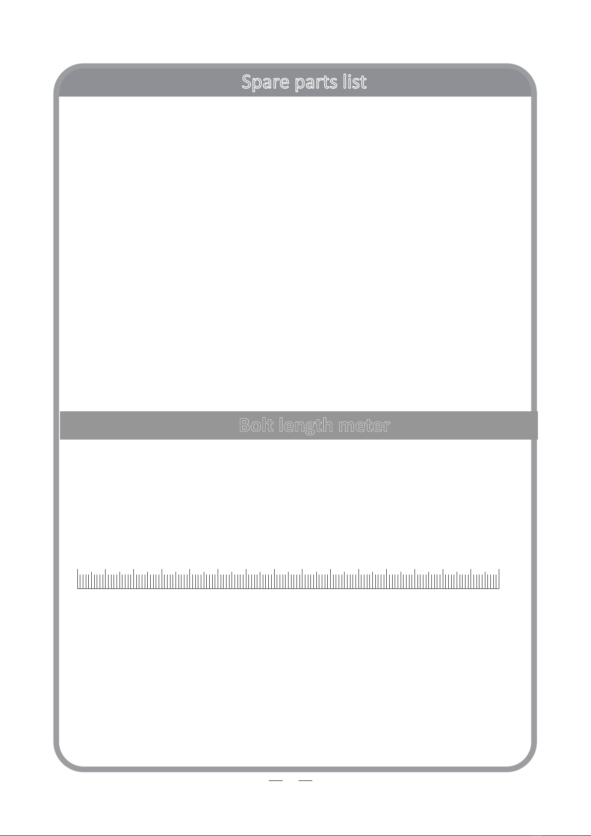
spare part list......................................................................................................................3-8
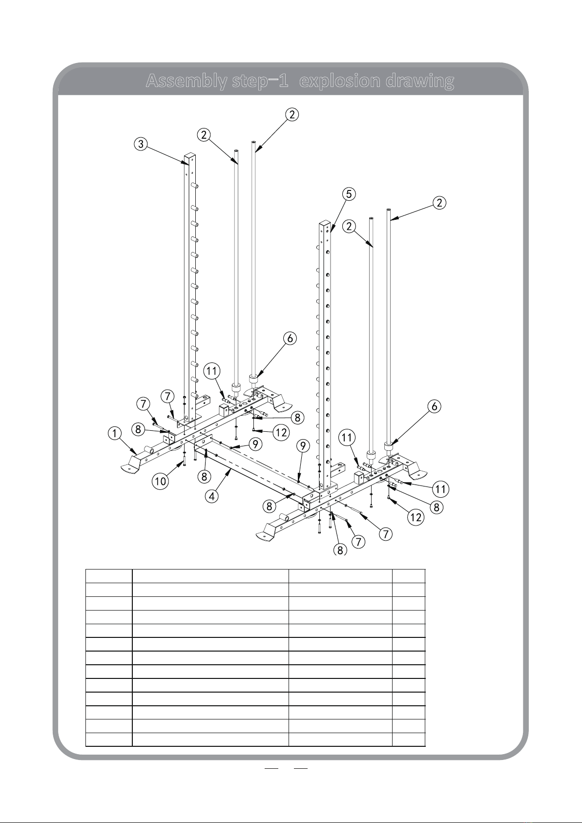
Assembly step 1..................................................................................................................9-12
Assembly step 2..................................................................................................................13-16
Assembly step 3................................................................................................................17-19
Assembly step 4................................................................................................................20-22
Assembly step 5................................................................................................................23-27
Assembly step 6................................................................................................................28-30
Assembly step 7................................................................................................................31-33
Assembly step 8................................................................................................................34-35
Assembly step 9................................................................................................................36-38
Assembly step 10..............................................................................................................39-42
Assembly step 11..............................................................................................................43-46
Assembly step 12..............................................................................................................47-49
Assembly step 13..............................................................................................................50-56
Extra parts
.......................................................................................................................57-60

Spare parts list
3
No.
Descripon
Note
Qty.
1
ground tube
2
2
front guide rod
φ25*2050
6
3
lestand tube
1
4
connect support tube
1
5
right stand tube
1
6
crush pad
4
7
hexagon bolt
M10*95
8
8
washer
Φ10
224
9
lock nut
M10
102
10
hexagon bolt
M10*70
12
11
hang sha
16
12
hexagon bolt
M10*16
14
13
3070 ground tube
2
14
square tube
□50*50*t1.5
6
15
oval mat
131*80*14
4
16
plain half hexagon rivet nut
M10
18
17
fix plate-bend
T6
6
18
hexagon bolt
M10*20
20
19
spring gasket
Φ10
34
20
3070 right stand tube
1
21
hang sha
Φ25*M12*98
28
22
tube plug
□50*70*t1.5
2
23
hexagon bolt
M12*25
34
24
spring gasket
Φ12
34
25
washer
Φ12
38
26
lestand tube
1
27
sliding sleeve
2
28
barbell bar
1
29
safety hook-right
1
30
rubber crush
Φ60*Φ26*25
4
31
safety hook-le
1
32
small handle
1
33
weight stack-130KG
2
34
magnec pin
2
35
sliding tube
2
36
rubber cover
2
37
lining bearing
LM25UU
6
38
bearing
6005
4
39
spring catch collar
Φ40
8
40
aluminum rod
Φ30*1158*T2.5
1

Spare parts list
4
No.
Descripon
Note
Qty.
41
hexagonal socket head cap screw
M6*16
4
42
3060 hook-right
1
43
3035 barbell inner rod
1
44
spring gasket
Φ6
4
45
hook-le
1
46
safety catch
2
47
lock nut
M12
2
48
safety hook
54511
2
49
3070 chin bar
2
50
50 connect plate-2 hole
120*50*T3
2
51
3070 chin tube
2
52
square tube
50*25
4
53
up decorate plate
4
54
3070 back up connect frame
1
55
hexagon bolt
M10*80
16
56
hexagon bolt
M10*75
50
57
back up connecon tube
1
58
decorate plate
1
59
Mushroom head break mandrel blind rivets
4*8
12
60
stainless guide-le
1
61
sliding tube right
1
62
stainless tube -right
1
63
sliding tube -le
1
64
chin up bar
1
65
stainless front stand tube-le
□50*50*2120
1
66
square tube
□50*50*t1.2
4
67
sliding tube-right
1
68
bush bearing
□60-□50
4
69
aluminium spring pin
2
70
hexagon bolt
M10*45
10
71
Φ95 pulley
21
72
pulley rotaon pin
Φ20*M10*67
2
73
pulley rotaon cover
2
74
powder metallurgy sleeve
Φ33.2*Φ29*Φ20*18
8
75
stainless front stand tube-right
□50*50*2120
1
76
sliding sleeve
□50*50*2120
1
77
3070 across connect plate
1
78
hang ring
1
79
washer
Φ8
46
80
lock nut
M8
10

Spare parts list
5
No.
Descripon
Note
Qty.
81
Injecon molded insert nut
M8
2
82
high pull handle
2
83
outer catch collar
Φ38.6*Φ32.8*25
2
84
hexagon socket set screw
M10*25
2
85
pulley frame
2
86
decorate adjust plate
Φ14*49*T1.5
6
87
powder metallurgy sleeve
Φ20*Φ16*Φ10.5*21.5
24
88
wire-ball bolt
2
89
32 tube plug
16
90
pulley adjust plate
4
91
3070 wire
2
92
gravity block bolt
M12
2
93
wire-splice head
2
94
wire-head
54511
2
95
wire-ball head
54511
2
96
hexagon socket cap screws
M5*25
2
97
3070 boom reinforcing plate
4
98
wire-hang nose
2
99
wire-nose nose
2
100
hexagon bolt
M10*25
10
101
wire-nose nose
2
102
wire-ball nose
4
103
3070 back shield
4
104
shield rod
4
105
hexagon bolt
M8*16
16
106
3035 barbell tube
2
107
rotaon tube
1
108
L shape pin
Φ17*250
4
109
barbell clamp
2
110
hexagon socket buon head screws
M12*40
2
111
barbell bar plug
Φ51*Φ42.5*36.6L
2
112
aluminum inner catch collar
Φ60*48.5*27L
2
113
stainless tube-310
Φ50*310*t0.5
2
114
inner lining tube
Φ48*298*t2.5
2
115
new rotaon rod
1
116
double barbell rotaon
1
117
powder metallurgy sleeve
Φ50*Φ25*15
2
118
rotaon pin
M12*Φ25*77
1
119
barbell bar plug
1
120
barbell bar limit sha
1

Spare parts list
6
No.
Descripon
Note
Qty.
121
limit ring
1
122
circle tube plug
Φ25*1.5
1
123
up connecon tube
1
124
up cross tube
1
125
hook
6
126
back stand tube
2
127
concave plate
120*52*T3
2
128
back connecon tube
1
129
hook
6
130
finger cover
Φ8*100
6
131
3070 back stand tube
2
132
barbell bar inner tube
10
133
3070 kele fix frame
1
134
3070 small handle fix tube
1
135
aluminium cap
Φ50*Φ11*11
10
136
outer cover tube
10
137
stainless outer tube
Φ50*0.8*200
10
138
hexagon socket buon head screws
M10*30
10
139
barbell bar tube
10
140
rubber gasket
Φ70*Φ50*10
10
141
kele frame
1
142
fix plate
1
143
cross recessed countersunk head screw
M6*12
3
144
small handle
1
145
rubber ring
1
146
ball shape chin up bar
2
147
buerfly clip
Φ50
10
148
ball shape chin up bar
2
149
right safety catch-long rubber
1
150
right safety catch
1
151
3070 footplate
1
152
3070 back support pad
1
153
move hook
1
154
move hook-right
1
155
short safety catch-le
1
156
short safety catch
1
157
85 T shape pin-black
2
158
leg press safety catch
1
159
leg curl tube
1
160
100 T shape pin-black
1

Spare parts list
7
161
long safety catch-outer rubber
387MM
2
162
long safety catch-right
1
163
long safety catch-right welding
1
164
3070 footplate
1
165
lock pin
2
166
back support tube
1
167
3070 waist pad
1
168
hexagon bolt
M8*70
4
169
move hook
1
170
move hook plate
2
171
hook connect sha
2
172
powder metallurgy sleeve
Φ26*Φ16*12
4
173
move hook-right
1
174
3070 short safety catch -le
1
175
roller sha
2
176
bearing
4
177
190 safety catch rubber
2
178
countersunk head socket head screw
M6*10
12
179
hexagon socket buon head screws
M10*110
2
180
3070 short safety catch -right
1
181
3070 leg press safety catch
1
182
85 new safety catch rubber
1
183
leg press adjust frame
1
184
pull pin
M18
1
185
sponge
Φ100*Φ25*175
2
186
sponge inner cap
2
187
sponge outer cap
2
188
hexagon socket buon head screws
M8*25
2
189
big handle
2
190
inner sha
Φ20*137*M10
2
191
3070 handle frame
2
192
handle tube
2
193
hexagon socket buon head screws
M10*25
4
194
across rod
1
195
spring catch collar
28
2
196
inner lining tube
1
197
inner sha
Φ17*38
2
198
washer
2
199
bearing
6001-2RS
2
200
bearing sleeve
2

Spare parts list
8
0 1 6 7 8 9 10 11 12 13 14 152 3 4 5
Bolt length meter
cm
No.
Descripon
Note
Qty.
201
T shape pin
2
202
T shape lining sleeve
4
203
U shape fastener
2
204
catch
5
2
205
hexagon socket buon head screws
M8*16
2
206
washer
Φ8
2
207
spring gasket
2
208
move hook plate
4
209
hexagon socket buon head bolt
M8*40
8
210
traingular handle
1

Assembly step-1explosion drawing
9
No. Descripon Note Qty.
1 ground tube 2
2 front
guide rod
3 lestand tube 1
4 connect support tube 1
5 right stand tube 1
6 crush pad 4
7 hexagon bolt M10*95 4
8 washer Φ10 20
9 lock nut M10 8
10 hexagon bolt M10*70 4
11 hang sha8
12 hexagon bolt M10*16 4
φ25*2050 4

Factory Assembly Drawing
10
ground tube
QTY: 2PCS/SET
No. Descripon Note Qty.
13 3070 ground tube 1
14 square tube □50*50*t1.5 1
15 oval mat 131*80*14 2
16 plain half hexagon rivet nut M10 2
17 fix plate-bend T6 1
18 hexagon bolt M10*20 2
19 spring gasket Φ10 2
8 washer Φ10 2
le stand tube
QTY: 1PCS/SET
No. Descripon Note Qty.
26 lestand tube 1
21 hang sha Φ25*M12*98 14
22 tube plug □50*70*t1.5 1
14 square tube □50*50*t1.5 1
16 plain half hexagon rivet nut M10 1
23 hexagon bolt M12*25 14
24 spring gasket Φ12 14
25 washer Φ12 14

Factory Assembly Drawing
11
3070 right stand tube
QTY: 1PCS/SET
No. Descripon Note Qty.
20 3070 right stand tube 1
21 hang sha Φ25*M12*98 14
22 tube plug □50*70*t1.5 1
14 square tube □50*50*t1.5 1
16 plain half hexagon rivet nut M10 1
23 hexagon bolt M12*25 14
24 spring gasket Φ12 14
25 washer Φ12 14

Assembly step-1drawing
12
Assembly step-1 installaon instrucon
1 Assembly guide rod-2 on ground tube-1,then cover crush pad-6 on guide rod-2 using M10*16 hexagon bolt-
12,Φ10 washer-8.
2
Assembly hang sha-11 on ground tube-1.
3 Assembly lestand tube-3,right stand tube-5 on ground tube-1,respecvely using M10*70 hexagon bolt-10,
Φ10 washer-8.
4 Assembly connect support tube-4 on ground tube-1 using M10*95 hexagon bolt-7,Φ10 washer-8,M10 lock
nut-9.
12501250 857.27 12501250 857.27 12501250 857.27 12501250 857.27
ATTENTION:
Please aenon the size of the
back and front.
To void the size back high
pull don’t suitble.

Assembly step-2explosion drawing
13
No. Descripon Note Qty.
27 sliding sleeve 2
28 barbell bar 1
29 safety catch-right 1
30 rubber crush Φ60*Φ26-25 4
31 safety catch-le1
2 front guide rod
33 weight stack-130KG 2
11 hang sha8
34 magnec pin 2
18 hexagon bolt M10*20 2
8 washer Φ10 2
19 spring gasket Φ10 2
φ25*2050 2
28
2
27
2
27
28
28
31
29
30
30
30
30
33
11
11
34
34
18 19
8

Factory Assembly Drawing
14
37
sliding tube
QTY: 2PCS/SET
No. Descripon Note Qty.
35 sliding tube 1
36 rubber cover 1
37 lining bearing LM25UU 2
38 bearing 6005 2
39 spring catch collar Φ40 2
barbell bar
QTY: 1PC/SET
No.
Descripon
Note
Qty.
40
aluminum rod
Φ30*1158*T2.5
1
41
hexagonal socket head cap screw
M6*16
4
42
3060 hook-right
1
43
3035 barbell inner rod
1
44
spring gasket
Φ6
4
45
hook-le
1

Factory Assembly Drawing
15
37
37
No. Descripon Note Qty.
37 lining bearing LM25UU 1
39 spring catch collar Φ40 2
46 safety catch 1
47 lock nut M12 1
25 washer Φ12 1
48 safety catch 54511 1
safety hook-right
QTY: 1PC/SET
QTY: 1PC/SET
safety hook-le
No. Descripon Note Qty.
37 lining bearing LM25UU 1
39 spring catch collar Φ40 2
46 safety catch 1
48 safety hook 54511 1
47 lock nut M12 1
25 washer Φ12 1

Assembly step-2 drawing
16
Assembly step-2 installaon instrucon
1
Assembly rubber crush-30,safety catch-right-29,sliding sleeve-27 on front guide rod-2.
2
Assembly rubber crush-30,safety catch-le-31,sliding sleeve-27 on front guide rod-2.
3
Assembly barbell bar-28 on sliding sleeve-27.
4 Assembly finish assmbly front guide rod-2 on ground tube-1 using M10*20 hexagon bolt-18,Φ10 washer-8,Φ
10 spring gasket-19.
5
Assembly weight stack-130KG-33 on front guide rod-2.
6
Plug magnec pin-34 into weight stack-130KG-33.

Assembly step-3 explosion drawing
17
719
49
17
8
918
18
19
8
50
No. Descripon Note Qty.
49 3070 chin bar 2
17 fix plate-bend T6 2
50 50 connect plate-2 hole 120*50*T3 2
18 hexagon bolt M10*20 10
19 spring gasket Φ10 10
8 washer Φ10 18
7 hexagon bolt M10*95 4
9 lock nut M10 4

Factory Assembly Drawing
18
3070 chin tube
QTY:2PCS/SET
No. Descripon Note Qty.
51 3070 chin tube 1
52 square tube 50*25 2
16 plain half hexagon rivet nut M10 2

Assembly step(3)drawing
19
Assembly step-3 installaon instrucon
1 Assembly fix plate-bend-17 on 3070 chin bar-49 using M10*20 hexagon bolt-18,Φ10 washer-8,Φ10 spring
gasket-19.
2 Assembly 3070 chin bar-49 on front guide rod-2 using M10*20 hexagon bolt-18,Φ10 washer-8,Φ10 spring
gasket-19.
3 Assembly 50 connect plate-2 hole-50,3070 chin bar-49 on lestand tube-3 using M10*95 hexagon bolt-7,Φ
10 washer-8,M10 lock nut-9 .
4 Assembly 50 connect plate-2 hole-50,3070 chin bar-49 on right stand tube-5 using M10*95 hexagon bolt-7,Φ
10 washer-8,M10 lock nut-9 .

Assembly step-4explosion drawing
20
No. Descripon Note Qty.
53 up decorate plate 4
54 3070 back up connect frame 1
55 hexagon bolt M10*80 4
8 washer Φ10 24
9 lock nut M10 12
56 hexagon bolt M10*75 8
9
54
56
53
53
56
55
8
9
8
56
Table of contents
Other Force Fitness Equipment manuals
Popular Fitness Equipment manuals by other brands

SKLZ
SKLZ PULLUP REVOLUTION Instruction manual and exercise guide

Kettler
Kettler SE 3600 Training and operating instructions

ETENON Fitness
ETENON Fitness PC20 owner's manual

Matrix
Matrix CXC manual

Body Solid
Body Solid K8439 Assembly & operating instructions

Nautilus
Nautilus 9NP-B7524 Series owner's manual