Force JX-DS913 User manual

OWNER’S MANUAL JX-DS913
Single Station Multi-Gym with chest press and leg extension/leg curl - 150lbs pin loaded weight stack
CAUTION!
Read all precautions and instructions in this manual before using this equipment.

、
This exercise equipment is built for optimum safety. However, certain precautions apply whenever you
operate a piece of exercise equipment. Be sure to read the entire manual before you assemble, operate
or use this equipment.
Assembly
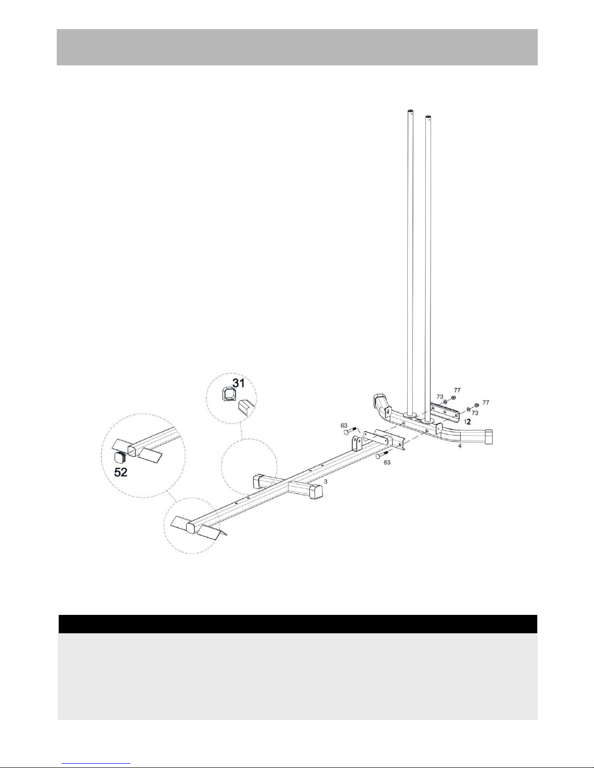
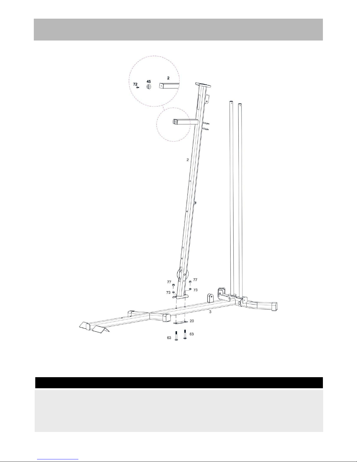
• The product must be installed on a stable and level
surface.
• Assemble the item as close to its final position
(in the same room) as possible.
• Make sure you have enough space to layout the
parts before starting.
• Keep children and animals away from the exercise
area, small parts could pose a choking hazard if
swallowed.
• Dispose of all packaging carefully and responsibly.
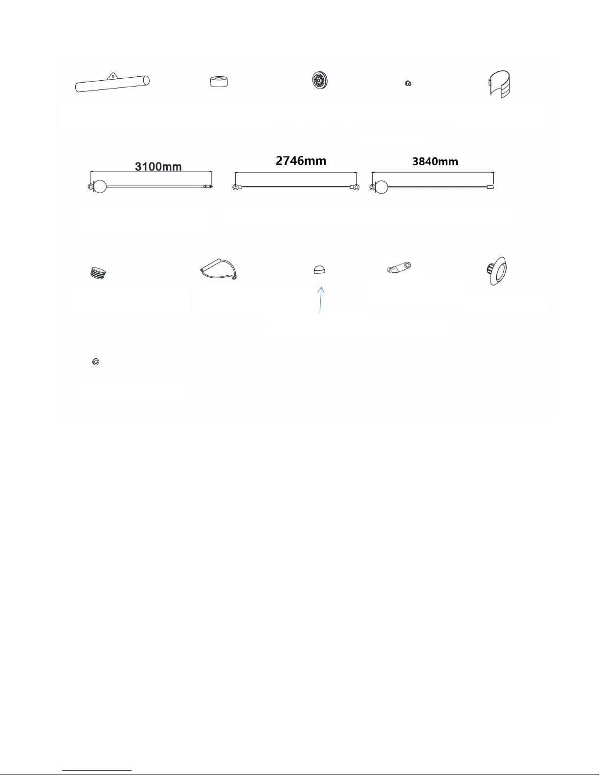
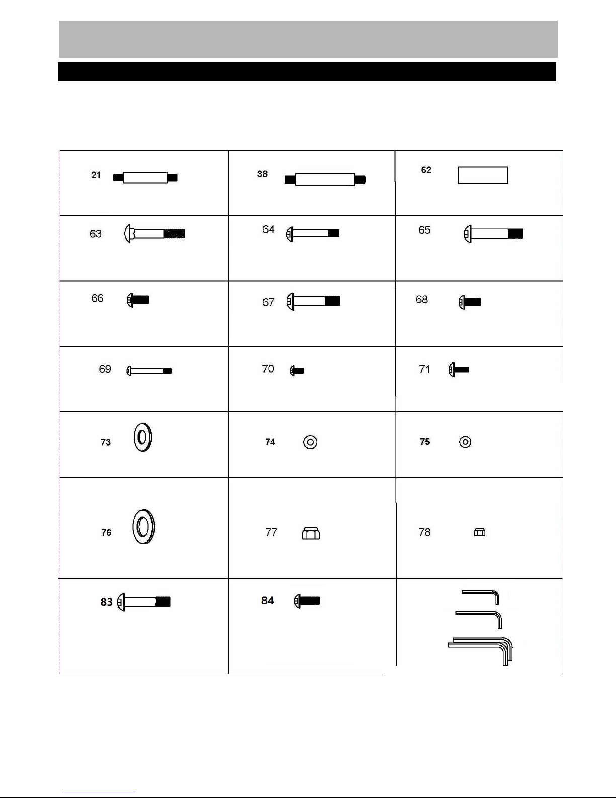
• Check you have all the components and tools
listed in the parts list, bearing in mind that, for
ease of assembly, some components are pre-
assembled.
• The assembly of this equipment is best carried out
by 2 people.
Use
• It is the responsibility of the owner to ensure that all
users of this product are properly informed as to how
to use this product safely.
• This product is intended for domestic use only.
Do not use in any commercial, rental, or institutional
setting.
•Use the equipment only for intended use, as
described in this manual. Do not use attachments not
recommended by the manufacturer.
• Keep this equipment indoors, away from moisture
and dust. Do not put the equipment in a garage,
outbuilding, covered patio, or near water.
• Your product is intended for use in clean dry
conditions. You should avoid storage in excessively
cold or damp places as this may lead to corrosion
and other related problems that are outside our
control.
• Keep unsupervised children away from the
equipment.
• Parents and others in charge of children should be
aware of their responsibility because the natural play
instinct and the fondness of experimenting of
children can lead to situations and behavior for which
the training equipment is not intended.
• If children are allowed to use the equipment under
supervision, their mental and physical development
should be taken into account. They should be
controlled and instructed to the correct use of the
equipment. The equipment is under no
circumstances suitable as a toy.
• Disabled persons should not use the equipment
without a qualified person or doctor in attendance.
This product is not suitable for therapeutic
purposes.
• Always wear appropriate workout clothing when
exercising. Do not wear loose or baggy clothing, as
it may get caught in the equipment. Wear trainers
to protect your feet while exercising.
•Do not place any sharp objects around the
equipment.
• Keep hands away from all moving parts.
• If any of the adjustment devices are left projecting,
they could interfere with the user’s movement.
• Before using the equipment to exercise, always
perform stretching exercises to properly warm up.
• Only one person at a time should use the
equipment.
• A spotter is recommended during exercise.
• If the user experiences dizziness, nausea, chest
pain, or other abnormal symptoms stop the workout
and seek immediate medical attention.
• Injuries to health may result from incorrect or
excessive training.
• This product is suitable for a maximum user weight
of: 120kg.
Warning: Before beginning any exercise program, consult your doctor. This is especially important
for people over the age of 35 or persons with pre-existing health problems or those who have not
exercised for a period of time. You MUST read all instructions before using any fitness equipment.
FORCE USA and its associates assume no responsibility for personal injury or property damage
sustained by or through the use of this product.
Important – Please read fully before assembly or use
Safety information
1

Note: Some of the smaller components may be pre-fitted to larger components. Please check carefully
before contacting us regarding any missing components.
Total mass of the product is 122.2 kg. Total size of the equipment is76.6 cm × 168.4 cm × 197 cm.
Components - Parts
Please check you have all parts listed below
10#Left butterflyX1PC
8# Front press baseX1PC
11# HandleX2PC
7# Leg developer X1PC
5# Leg developer holderX1PC
6# Seat pad supportX1PC
2
15# Cross double
floating pulley
bracketX1PC
13#Arm curl pad supportX1PC
4# Rear stabilizerX1PC
3# Base FrameX1PC
2# Front Vertical FrameX1pc
1# Upper FrameX1 PC
14# Swivel pulley bracketX2PCS
12# U shape BracketX1PC
9# Right butterflyX1PC

18# Lat barX1PC
36# Weight plateX13PCS
35#Weight stemX1PC
34# 7#Gourd hookX5PCS
3
33# 15 joint ChainX2PCS
32# Selector PinX1pc
30# Double floating
pulley bracketX2PCS
29# Weight stack cover
bracketx2pc
28# Foam roll X4PCS
27# Foam roll X2PCS
26#Arm curl pad X1PC
25# Seat pad X1PC
24# Backrest pad X1PC
19# Selector Rod X1PC
23# Foam Roll tubeX2PCS
17# Guide RodX2PCS
20# BracketX4PCS
16# Weight stack coer
X1PC
22# Lock Knob X1PC

47# Ankle StrapX1PC
43#BushingX16PCS
42# Pulleyx18pcs
41# Rubber bumperX2PC
50#Lower cableX1Pc
49# Butterfly cableX1PC
53#φ50 End cap×5
57# Single StrapX1PC
58# M10 aircraft nut coverX4PCS
61#RetainerX8PCS
82# BushingX8PCS
80# End capX4PCS
48#Upper CableX1 Pc
4
39# Handle X1PC

Note: The quantities below are the correct amount to complete the assembly. In some cases more
hardware may be supplied than are required. Some of the fixings are pre-fitted to the larger components.
Please check carefully before contacting us regarding any missing fixings.
Components - Fixings
Please check you have all parts listed below
5
4#,5# Allen bolt wrench Each one
6# Allen bolt wrenchX2
M10*30 Allen boltX1
M10×50mm Allen boltX4
M6 Aircraft nut X2
M10 Aircraft nutX39
Φ25washer ×6
Φ6washer ×10
Φ8washer ×8
Φ10washer ×50
M6×20mm Allen boltX8
×8
M8X16Allen boltX6
M8×70mm Allen bolt×2
M10×20mm Allen bolt×2
67#M10×45mm Allen boltX6
66#M10×25mm Allen BoltX6
M10*55Allen boltX2
M10×65mm Allen boltX12
×12
M10×70mm Carriage bolt×10
57MM swivel axleX1
Front press base axleX1
Butterfly axle X 2

Assembly Instructions
Insert 2 pcs guide rods (17#) into the holes of the Rear Stabilizer(4#) separately and tighten them with 2
pcsM10*25 Allen Bolt(66#) and 2pcs φ10 washers(73#).
Notes: part (31), were pre-fitted in the factory already.
Step 1
6

7
4
Step 2
7
Assembly Instructions
Attach the Base Frame(3#) to the Rear Stabilizer(4#) as the diagram shows and tighten them with 2pcs
M10*70 carriage bolt(63#),1pc bracket(12#),2pcs φ10 washers(73#) and 2pcs M10 Aircraft nuts(77#)
Notes: part (31)(52), were pre-fitted in the factory already.

Assembly Instructions
a. Attach the front vertical frame(2#) onto the base frame(3#). Carefully align the holes and secure them
with M10*70 carriage bolt(63#), 1 pc bracket(20#),2pcs φ10 washers(73#) and 2pcs M10 Aircraft
nuts(77#) .
Notes: part (45) is pre-fitted.
Step 3
8

Assembly Instructions
Place 13pcs weight plate(36#) along the guide rods(17#) from the top to the bottom, Insert the Selector
Rod(19#) into the center hole of the weight plates. And then place the weight stem(35#) again.
Select the desired weight with the selector pin(32#) during the exercising.
Notes: Part (51#) is pre-fitted.
Step 4
9

Assembly Instructions
Place the Upper Frame(1#) onto the Front Vertical Frame(2#) and 2pcs Guide Rod(17#), Align the holes
and secure them with 2pcs M10*25 Allen Bolt (66#),2pcs φ10 washers(73#) ,2pcs M10*70 Carriage
bolt(63#),1 pc bracket(20#),2pcs φ10 washers(73#),2pcs M10 Aircraft nuts(77#) .
Step 5
10

Assembly Instructions
a.Attach the seat pad support(6#) to the front vertical frame(2#) and secure them with 2pcs M10*70
Carriage bolt(63#),1pc bracket(20#),2pcs φ10 washers(73#),2pcs M10 Aircraft nuts(77#) .
b.Attach the Leg developer Holder(5#) onto the base frame, Secure them with 2pcs M10*70 Carriage
bolt(63#),1pc bracket(20#),2pcs φ10 washers(73#),2pcs M10 Aircraft nuts(77#) .
c.Attach the Leg Developer Holder(5#) and another end of the seat pad support (6#)together,Secure
them with 2pcs M10*65 Allen Bolt (64#),4pcs φ10 washers(73#) and 2pcs M10 Aircraft nuts(77#) .
Step 6
11

Assembly Instructions
Step 7
Attach the Weight Stack Cover(16#)and 2pcs Weight stack Bracket(29#) as the diagram show,
Secure them with 8pcs M6×20mm Allen Bolt(#71),10 pcs φ6 washers(#75),2pcs M6 Allen Bolt(78#),
12

Assembly Instructions
Step 8
Attach the Front Press Frame(8#) to the Upper Frame(1#), Secure them with 1pcs axle(38#),2pcs φ10
washer(76#)and 2pcs M10 Aircraft nut (77#).
13

Assembly Instructions
Step 9
Attach the Right butterfly(9#) to the front press base(8#),Secure them together with 1pc butterfly
axle(21#),2pcs φ10 washer (76#),2pcs M10 Aircraft nut(77#) and 2cps nut cover(58#).
Push 1pc butterfly foam roll(27#) as the diagram shows.Attach the handle(11#) into the hole of the
butterfly ans secure them with 1pc M10×55 Allen Bolt (65#),1pc M10×20 Allen Bolt (68#) and 2pcs φ
10 washer(73#).
Repeat the same way to install the left butterfly.
14

Assembly Instructions
Step 10
Attach the seat pad (25) onto the seat pad support and secure it with 4pcs M8×16 Allen Bolt
(70#),4pcs φ8 washer(74#).
Attach the backrest pad(24#) to the front vertical frame(2#), Secure it with 2pcs M8×70 Allen Bolt
(69#)and2pcs φ8 washer(74#).
15

Assembly Instructions
Step 11
Attach the Arm Curl Pad support(13#) into the Leg Developer Holder and select the desired height with
1pc Lock Knob(22#).
Attach the Arm curl pad (26#) to the support and secure it with 2pcs M8×16 Allen Bolt(70#) and 2pcs
φ8 washer (74#).
16

Assembly Instructions
Step 12
Attach the Leg Developer(7#) to the bracket and secure it with 1pc Axle(62#),2pcs φ10 washer
(73#),2pcs M10×25 Allen Bolt(66#).
Insert the 2pcs Foam Roll tube(23#) as the diagram shows. And push 4pcs form roll(28#)from both
ends and then push 4pcs End Cap (80#) again .
17

Assembly Instructions
18

Step 13
Important: Study and follow the diagram carefully.
A. Attach the swivel pulley bracket(14#) to the support as the diagram shows, and secure it with 1pc
M10*65Allen Bolt (64#) ,2X φ10 washer (73#) and 1pcM10 Aircraft nut (77#).
BAttach the end of the 2745 MM butterfly cable(49#) to the hook and place 1X pulley (42#) below the
cable , Secure the pulley to the swivel pulley bracket(14#) with 1X M10X45 Allen bolt (67#),2X φ10
washer (73#) and 1pcM10 Aircraft nut (77#).
CDraw the cable around the pulley and downwards ,Place 1X pulley (42#) onto the cable , Secure the
pulley with cross double floating pulley bracket(15#) together with the 1pc M10*50 Allen Bolt(83#),2pcs
φ10 washers(73#),bushing(82#), 2 pcs retainer(61#),and 1 pc M10 Aircraft nut(77#).
DDraw the cable around the pulley and upwards, Install another pulley with the same way in above A
and B.
19
Table of contents
Other Force Fitness Equipment manuals