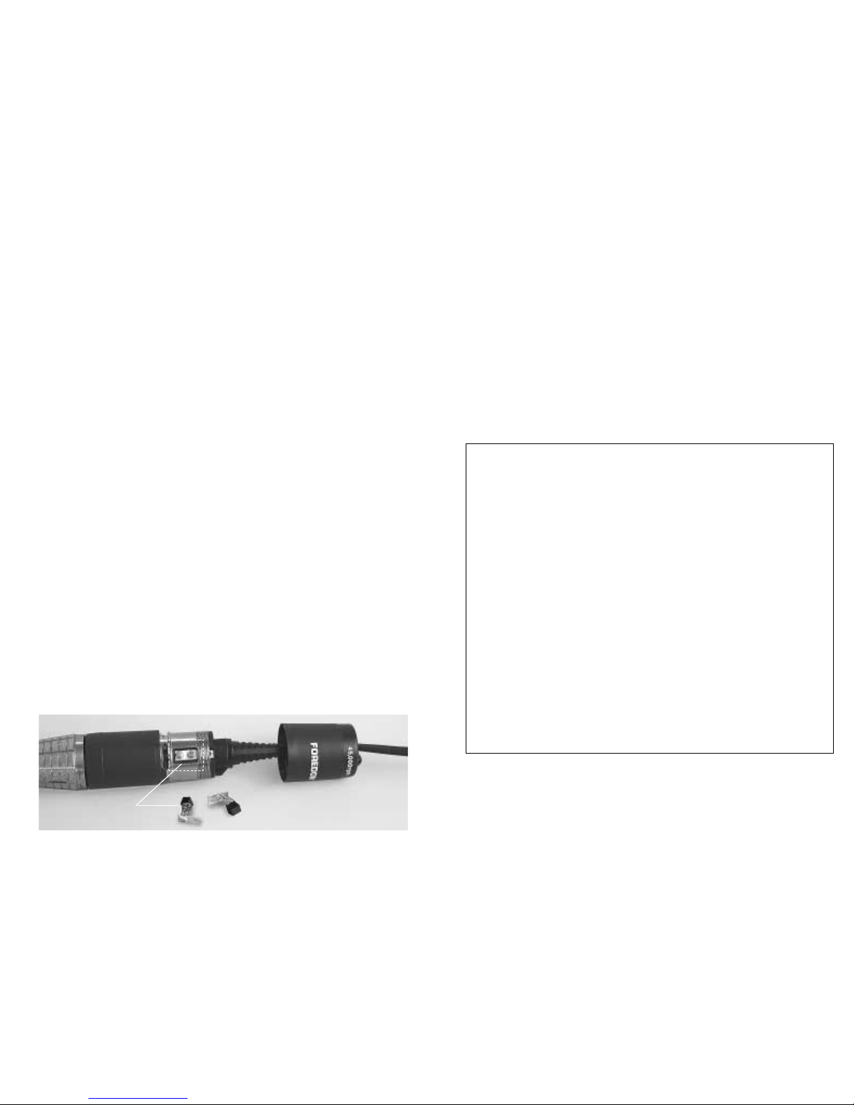
FOREDOM 1045 User manual

Safety Instructions
• ALWAYS wear proper eye and face protection.
Safety glasses have been provided with your new Micro Motor. For your
own protection, they should be worn (or a face shield) whenever you
operate a Foredom®or any power tool to prevent serious eye or
face injuries.
• ONLY use accessories rated for 45,000 rpm or higher speeds when
operating this micro motor.
• ALWAYS find out the manufacturer's speed rating before using any
accessory.
•NEVER use or continue to use any accessory which appears to be
damaged, loose, vibrating or out of balance. Inspect each accessory for
cracks or flaws before using it.
•ALWAYS insert the shank or arbor of an accessory or mandrel into the
collet or chuck of the handpiece as far as possible in order to provide
proper support and close the collet or chuck securely.
•NEVER use excessive side pressures which may tend to bend or
break the shank or arbor of an accessory. Let the speed of the accessory
do the work.
•DO NOT stall the motor by jamming or using excessive pressure on the
mounted point, buff, wheel or accessory. This can result in damage
to the motor.
•WEAR a dust protector to prevent you from inhaling harmful dust or debris
from grinding, carving or other operations performed with this power tool.
A Micro Motor Handpiece is a high speed rotary power tool which
can be dangerous and cause serious injury if it is not used properly.
NEVER operate it without wearing eye protection.
2
Operation and
Maintenance Manual for
1045 Micro Motor Kit
FOREDOM®
For Your Safety:
•Read this Manual before operating your
Foredom Micro Motor Power Tool.
•Always wear eye protection while using
the Foredom Micro Motor Handpiece.
FM3545
Control
FC-2000
Foot Pedal
MH-145A
Handpiece
3/32″& 1/8″Collets,
Spare Motor Brushes

3
Assembly Instructions
Do not plug into power outlet before connecting handpiece or
foot pedal.
Connecting Handpiece:
Attach the handpiece to the control by plugging the coiled cord into the
handpiece connection port on the lower right side of the front control panel
(see Figure 1). Be sure to align pins properly using keyway when plugging in
the cord.
NEVER turn or start the MH-145A Handpiece while chuck is in open
(unlocked) position. This can damage the handpiece. Always operate it
with a bur or other accessory in the chuck and with the chuck in the
closed position.
DO NOT operate the handpiece in the presence of any flammable liquid
or gas.
DO NOT cover the ventilation slots or handpiece motor with cloth or tape.
Air must pass freely through the intake and exhaust ventilation slots to prop-
erly cool the motor. If the power cord or plug to the handpiece is damaged,
repair or replace immediately. NEVER operate with a damaged power cord.
Connecting Foot Pedal:
The Foot Pedal Control can be used with either 115 Volt or 230 Volt models
of the control. Attach it by inserting the foot pedal connector pins into the
foot control connector port on rear panel of control (see Figure 2) using
keyway to properly align pins. Then tighten the threaded locking collar by
turning it clockwise. (It is not necessary to have the foot pedal connected to
the control box to operate the dial speed control.) The Micro Motor control
and handpiece are now ready to operate.
Front Panel (Figure 1)
Rotation
Selection Switch
Handpiece
Connection Port
Power
On/Off
Switch
Rear Panel (Figure 2)
Manual Dial
Speed Control
Control
Selector Switch
Key
way
Plug
Foot Control
Connection Port
Fuse
Keyway
Power
On/Off
Indicator
Light
Connecting Power Cord:
Before connecting power cord plug (see Figure 2) to a power outlet, put the
On/Off Selector Switch in the OFF position and turn the dial to the LOW
speed position. Be sure that the handpiece chuck is closed with (or
without) an accessory in it. (Operating the handpiece with the chuck in the
open position can severely damage the motor of the handpiece.) Now plug
in the power cord to a 115 Volt (or 230 Volt) AC current outlet. Refer to the
section below for selecting the Manual/Foot and Forward/Reverse switches.
Operating Instructions
FM3545 Control
Power On/Off Switch and Indicator Light:
With the Power On/Off Switch in the ON position and the Control Selector
Switch in the MANUAL position, the Power Indicator Light will go on
immediately and the handpiece will run at the speed set on the
Dial Speed Control.
With the Power On/Off Switch in the ON position and the Control Selector
Switch in the FOOT position, the Power Indicator Light will go on but the
handpiece will not rotate until the Food Pedal is depressed.
Control Selector Switch:
With the Power On/Off Switch in the OFF position, select either foot or
manual speed control.
Forward/Reverse Rotation Selection Switch:
With Power On/Off Switch in OFF position, select the desired handpiece
direction by moving switch to FORWARD or REVERSE position. Do not
change handpiece direction while it is running. This can damage the
handpiece motor.
Manual Dial Speed Control:
The dial control will vary handpiece speed from low to full speed. It will only
function while Power On/Off Switch is in ON position and Control Selector
Switch is in MANUAL position.
Handpiece Overload Protection:
If the Handpiece is used with a locking ring left in the “R” position or in
overload condition, it will trigger the overload circuit protector. The Power
ON light will change in color from green to red and handpiece will stop.
Immediately turn off control by putting Power ON/OFF switch in OFF
position. Put power switch in ON position again when overload condition
is corrected.
4

5
Fuse Protection:
The transformer and control circuit board are protected from power line
current surges or shorts by a 1.5 Amp fuse in fuse holder in rear panel of
control (see Figure 2, page 3). It can be checked or replaced by unscrewing
cap and inserting a new fuse if necessary.
MH-145A Micro Motor Handpiece:
The MH-145A Micro Motor Handpiece is intended only for fine finishing
and detailing work. It should not be used to remove large amounts of
material in carving or other applications. If the handpiece is misused
or abused, it will not be covered under warranty.
Changing Accessories:
Burs and other accessories can be inserted or removed from the
handpiece collet when the collet is open.
To open the collet–
1. Put the power switch on control box in OFF position and wait for
handpiece to stop rotating.
2. Twist locking ring toward “R” until collet snaps open.
3. Insert shank of accessory fully (about 11⁄8″) into collet for
maximum support.
4. Twist knurled grip toward “S” until it snaps to lock collet.
Never turn power on to handpiece when collet is open. The spindle is in
a locked position and will not turn which will result in damage to the motor.
Collets Available for the MH-145A Handpiece:
Part No. HP813516: 3/32″(2.35mm) Collet (supplied)
Part No. HP813517: 1/8″Collet (supplied)
Part No. HP813518: 3mm Collet (optional)
Collet Adapters:
Use collet adapters with different shank size accessories without having to
change collets. Accessory
Collet Size Shank Size
Part No. HPLA-3234: 1/8″to 1/16″1/16″
Part No. HPLA-3235: 3mm to 3/32″3/32″
Part No. HPLA-3236: 1/8″to 3/32″3/32″
Installing/Changing Collets:
The 1045 Micro Motor Kit comes with a 3/32″collet in your handpiece and a
1/8″collet that is quick and easy to install with the collet changing wrench
shown below in Figure 3.
1. Twist locking ring
on handpiece
toward “R” position
until collet snaps
open. In this open
position, the spindle
remains locked in
place and cannot
spin freely.
2. Place collet changing wrench over front of collet with triangle shaped hole
aligned as shown in Figure 4.
3. Loosen collet by turning wrench counterclockwise while looking down on
the upturned handpiece like a clock face. Remove collet.
4. Insert new collet. Finger tighten down in a clockwise motion until you
meet some resistance. Apply wrench and continue making several more
turns for a secure fit.
Caution: Collet must be tightened with a wrench until it cannot be
turned farther. This will involve several turns beyond the initial
perceived spot of resistance achieved by finger tightening. If collet
is too loose or absent, spindle will not turn.
6
Figure 4
Figure 3
Locking ring
Collet changing
wrench
1/8″collet
3/32″collet
installed in
handpiece

Figure 5
7
Brush
Assembly
Maintenance
The MH-145A has permanently lubricated ball bearings that do not
require lubrication. Putting even a small amount of oil into the
handpiece can damage it.
Cleaning Handpiece:
Use the Handpiece in as clean and dust free an environment as possible.
If the Micro Motor Handpiece is used for woodcarving, it should be
cleaned after every use. Open handpiece and wipe dirt, chips or dust out
with a clean cloth. A cloth with a small amount of alcohol solution can be
used to clean outside of handpiece if necessary. Do not use any other
cleaning fluids or immerse handpiece in any liquid. The MH-145A
Handpiece is not autoclaveable.
Checking/Changing Carbon Brushes:
A spare set of carbon brushes is supplied with each handpiece. Depending
on how long the handpiece is used each day, the brushes should be
checked for wear periodically (about every 200 hours of use) and replaced
when the brush is less the 2mm (5/64″) long.
To Check/Replace Motor Brushes:
1. Unscrew protective cap from rear of motor (see Figure 5) by turning in
counterclockwise direction while griping handpiece body. (It has a
standard right hand thread.)
2. With small crosspoint screwdriver remove screws and brush assemblies
one at a time. Check length of carbon brush from spring to curved side of
brush. Brushes should be removed, examined, and replaced (if
necessary) one at a time. Pay careful attention to the orientation of
the brush curve in relation to the curve of the motor armature.
This same orientation must be maintained when replacing brushes.
3. Re-insert brush assembly or new brush assembly into brush tube.
Replace and tighten screws.
4. Screw protective cap back onto rear of motor housing so that top of
brush assembly is completely covered.
For More Information
For more information on Foredom machines, handpieces or accessories,
contact your local dealer. When no local dealer is available, write, call or fax:
The Foredom Electric Company, 16 Stony Hill Road, Bethel, CT 06801
(203)792-8622, Fax: 203-796-7861. Visit on line at: www.foredom.com
Form No. 1259a 7/02b Printed in U.S.A.
Foredom warrants its product to be free of defects in material or workmanship
for a period of one year after purchase.
During the warranty period, the defective product will be repaired or replaced
without charge or, at our option, the purchase price will be refunded. This
warranty does not cover damage caused in transit or by accident, misuse, or
ordinary wear.
ALL IMPLIED WARRANTIES, INCLUDING BUT NOT LIMITED
TO WARRANTIES OF FITNESS AND MERCHANTABILITY, ARE
HEREBY LIMITED IN DURATION TO A PERIOD ENDING ONE YEAR
FROM DATE OF PURCHASE, AND WE WILL NOT BE LIABLE OR
RESPONSIBLE FOR ANY SPECIAL OR CONSEQUENTIAL DAMAGES:
Repair or replacement will be made at our option if the product is returned
postpaid to:
The Foredom Electric Company, 16 Stony Hill Road, Bethel, CT 06801
All warranty repairs must be done at the factory at the address above. We will
not pay any shipping or transportation charges.
This warranty only covers the original purchaser of the product. Proof of
purchase may be requested.
Some states do not allow limitations on how long an implied warranty lasts, so
the above limitation may not apply to you. This warranty gives you specific legal
rights, and you may also have other rights which vary from state to state.
Repair Services
Authorized repair service is available at the Foredom factory in Bethel, CT. Send
items for repair to the factory marked “Attention: Repair Department”. Enclose the
item(s), a packing list, and information regarding the problem or repairs required.
Estimates of repair cost will be made upon request. It is our policy not to proceed
with a repair without your approval if the cost (labor plus parts) is more than fifty
percent of the cost for a new replacement. You will be notified by mail and advised of
the cost to repair and to purchase a new replacement. Please allow three business
days for an estimate to be done and five to seven business days for repair work to
be completed after we receive your approval to proceed.
Owner’s Registration Card
Send your Owner's Registration Card to Foredom right away. We will keep your card
in our Owner's Registration File.
Warranty
Table of contents
Other FOREDOM Power Tools manuals

FOREDOM
FOREDOM SR User manual

FOREDOM
FOREDOM K.1050 Manual

FOREDOM
FOREDOM K.103018 User manual

FOREDOM
FOREDOM K.1060 User manual

FOREDOM
FOREDOM TX Series User manual

FOREDOM
FOREDOM SR Series 1/6 HP User manual

FOREDOM
FOREDOM H.18 Installation instructions manual

FOREDOM
FOREDOM CC Series User manual

FOREDOM
FOREDOM SR Series User manual

FOREDOM
FOREDOM H Series Installation instructions