Forma Scientific 1284 User manual

Forma Scientific, Inc.
Millcreek Road, P.O. Box 649
Marietta, Ohio 45750
U.S.A. Telephone: (740) 373-4763
Telefax: (740) 373-4189
_____________________________________
Models:
1284, 1285, 1286, 1287,
1288, 1290, and 1291
Biological Safety Cabinets
Class II, Type A/B3
Manual No: 7001284 Rev. 10
Read This Instruction Manual
Failure to read, understand and follow the instructions in this manual may result in
damage to the unit, injury to operating personnel and poor equipment performance.
Refer to the serial tag on the
rear cover of this manual

FormaModel 1280/1290 Series ______________________________________________
i
The material in this manual is for information purposes only. The contents and the product it
describes are subject to change without notice. Forma Scientific, Inc. makes no representations or
warranties with respect to this manual. In no event shall Forma Scientific, Inc. be held liable for any
damages, direct or incidental, arising out of or related to the use of this manual.
Manual No. 7001284
10 19029/HD-1295
19002/SI-7906 6/16/00 Added exclusion on FLA rating
Wire harness chg (1284 & 1285-72 drawings) ccs
9 18861/HD-1283
18863/HD-1283 4/12/00 Model 1286 Blower motor change, updated Section 9.2 ccs
8 18826/HD-1286 2/28/00 Added mercury disposal warning ccs
7 HD-1265 2/4/00 Revise 1284-72 (rev. 8) ccs
6 18492/HD-1265
18548/HD-1265 1/17/00 Universal Piping Option Changes
Hinged Control Panel ccs
-- 18582/HD-1269 11/2/99 Added air flow test sheet to Certifier Listing Section ccs
5 18405/HD-1263 8/12/99 Updated 1290 parts list/schematic (lights) ccp
REV ECN DATE DESCRIPTION BY
WARNING! Lamps, thermometers and thermoregulators contain
mercury. Do not put in trash. Recycle or dispose as hazardous waste.

FormaModel 1280/1290 Series _________________________________________Service
ii
Do You Need Information or Assistance on Forma Scientific
Products?
do, please contact us 8:00 a.m. to 7:00 p.m. (Eastern Time) at:
1-740-373-4763 Direct
1-888-213-1790 Toll Free, U.S. and Canada
1-740-373-4189 FAX
http://www.forma.com Internet Worldwide Web Home Page
If you
Our staff can provide information on pricing and give you quotations. We
can take your order and provide delivery information on major equipment items or make
arrangements to have your local sales representative contact you. Our products are listed on the
Internet and we can be contacted through our Internet home page.
Our staff can supply technical information about proper setup,
operation or troubleshooting of your equipment. We can fill your needs for spare or replacement
parts or provide you with on-site service. We can also provide you with a quotation on our
Extended Warranty for your Forma products.
Whatever Forma products you need or use, we will be happy to discuss your
applications. If you are experiencing technical problems, working together, we will help you
locate the problem and, chances are, correct it yourself...over the telephone without a service
call.
When more extensive service is necessary, we will assist you with direct factory trained
technicians or a qualified service organization for on-the-spot repair. If your service need is
covered by the warranty, we will arrange for the unit to be repaired at our expense and to your
satisfaction.
Regardless of your needs, our professional telephone technicians are available to assist
you Monday through Friday from 8:00 a.m. to 7:00 p.m. Eastern Time. Please contact us by
telephone or fax. If you wish to write, our mailing address is:
Forma Scientific, Inc.
Millcreek Road, PO Box 649
Marietta, OH 45750
International customers please contact your local Forma Scientific distributor.
Sales Support
Service Support

FormaModel 1280/1290 Series ____________________________________ Safety
iv
General Safety Notes used in this Manual
Alerts the user to important operating and/or maintenance
instructions. May be used alone or with other safety symbols.
Read the accompanying text carefully.
Potential electrical hazards. Only qualified persons should
perform the instructions and procedures associated with this
symbol.
Hazard. Do not touch. Instructions associated with this symbol
should only be carried out when using special handing equipment
or when wearing special, protective clothing.
Potential biological hazards. Proper protective equipment and
procedures must be used when following instructions associated
with this symbol.
Reference O.S.H.A. Regulation 1910-1030.
Potentially hazardous energy. Equipment being maintained or
serviced must be turned off and locked off to prevent possible
injury. Reference O.S.H.A. Regulation 1910-147.
Hot surface(s) present which may cause burns to unprotected
skin or to materials which may be damaged by elevated
temperatures
Warning. Skin damage and/or eye injury can result from the light
produced by ultra violet light sources installed in this equipment.
Never work in this unit with the ultra violet light operating.
√
√√
√Always use the proper protective equipment (clothing, gloves, goggles etc.).
√
√√
√Always dissipate extreme cold or heat, or wear protective clothing.
√
√√
√Always follow good hygiene practices.
√
√√
√Each individual is responsible for his/her own safety.

FormaModel 1280/1290 Series __________________________________Contents
vi
Table Of Contents
Page
Section 1 - Receiving
1.1 Unpacking List........................................................................1-1
Section 2 - Introduction
2.1 Description .............................................................................2-1
2.2 Theory of Operation................................................................2-1
Section 3 - Installation
3.1 Location .................................................................................3-1
3.2 Power Connection...................................................................3-1
3.3 Plumbing Connection...............................................................3-1
a. Universal Plumbing Option..................................................3-2
3.4 Exhaust Requirements .............................................................3-2
a. Direct Room Exhaust..........................................................3-2
b. External Exhaust System.....................................................3-2
3.5 Remote Alarm Contacts, Model 1288, 1290 and 1291...............3-3
Section 4 - Operation
4.1 Control and Indicating Devices ................................................4-1
Section 5 - General Cautions
5.1 General Caution Notes.............................................................5-1
Section 6 - Cabinet Start-Up
6.1 General Recommendations.......................................................6-1
6.2 Use of Auxiliary Equipment in the Cabinet ...............................6-1
6.3 Cabinet Checklist ....................................................................6-1
6.4 Start-Up Procedure .................................................................6-2
Section 7 - Troubleshooting
7.1 Troubleshooting Guide............................................................7-1

FormaModel 1280/1290 Series __________________________________Contents
vii
Page
Section 8 - Maintenance
8.1 Checking the Static Pressure Gauge "Zero"..............................8-1
8.2 Re-zeroing the Static Pressure Gauge ......................................8-1
8.3 Adjusting the Damper..............................................................8-1
8.4 Biological Safety Cabinet Test Grids........................................8-3
Section 9 - Service
9.1 Replacing the Blower Motor (Model 1284 Series) ....................9-1
9.2 Replacing the Blower Motor (Model 1286 Series) ...................9-2
9.3 Replacing the Filters (All Models) ...........................................9-3
9.4 Replacing the Control Panel (All Models).................................9-5
Section 10 - Specifications ...........................................................................10-1
Section 11 - Accessories...............................................................................11-1
Section 12 - Parts List....................................................................................12-1
Section 13 - Schematics................................................................................13-1
Section 14 - Warranty Information...............................................................14-1
Section 15 - Certifier Listing.........................................................................15-1
(Separate manual included)

FormaModel 1280/1290 Series ____________________________________Receiving
1-1
Section 1 - Receiving
1.1 Unpacking List
Included with the installation/operation manual are four identification index buttons.
These buttons may be used to identify the type of service supplied to the service valves. Also
included in a separate bag attached to the drain handle, is a small Allen wrench used for
calibrating the Static Pressure Gauge. This Allen wrench should be kept with the manual at
all times.

FormaModel 1280/1290 Series ___________________________________Introduction
2-1
Section 2 - Introduction
2.1 Description
The Models 1284, 1285, 1286, 1287, 1288, 1290 and 1291 are Class II, Type A/B3
cabinets. The "Type A/B3" designation indicates two alternative uses of the cabinet. When
vented directly into the laboratory room, the unit serves as a "Type A" unit. When vented to
the outside atmosphere, through an in-house exhaust system, it serves as a "Type B3" unit.
Either usage of the cabinet offers both personnel and product protection.
The cabinet can be used in low-to-moderate risk environments and is designed to
NSF, International Standard #49. Class 1, 2, and 3 (low-to-moderate risk) agents are
described in the "Biosafety In Microbiological And Biomedical Laboratories"; CDC NIH
Publication No. (NIH) 88-8395, 3rd Edition, May 1993.
The cabinet's window permits the user to place auxiliary equipment and research
implements in the work area. The work opening must be held to 10 inches during all work
procedures. If the window is raised higher than the designated 10 inches, the air barrier at the
front of the cabinet will be weakened and containment will be seriously impaired.
2.2 Theory of Operation
Clean, filtered air descends through the work zone with approximately 40% being
discharged through the exhaust HEPA filter with the remaining air recirculating through the
supply HEPA filter into the work area. Exhausted air is replaced by room air entering the
system through the front access opening.
Room air entering the work zone, through the front access opening, completes the
air barrier at the unit face and is responsible for the containment properties of the unit. All
work must be performed beyond the intake grille, on the solid work tray.

FormaModel 1280/1290 Series _____________________________________Installation
3-1
Section 3 - Installation
3.1 Location
Locate the cabinet on a firm, level surface in an area of minimum temperature
changes. The cabinet should be placed away from disruptive air currents caused by excessive
personnel traffic, air-conditioning or heating ductwork, or laboratory windows and doors.
Proper cabinet location is important, as drafts disrupt critical airflow characteristics and
allow room contaminants to enter or escape the cabinet work area.
Where space permits, fourteen inches should be allowed on each side of the cabinet
for maintenance. A twelve-inch height should be available from the top of the cabinet to the
ceiling.
Place a bubble-type level on the work surface. Adjust the leveling feet until the
cabinet is level and the most comfortable working height is achieved. Ensure that all four
leveling feet are fully flush against the floor to prevent vibration.
3.2 Power Connection
The electrical wall outlet leading to the cabinet should be accessible for electrical
testing. This cabinet is equipped with one power cord supplying power to the blower, lights
and receptacles. The cord should be plugged into a dedicated circuit. Refer to Section 9 or to
the serial plate on the front of the unit for electrical specifications.
3.3 Plumbing Connection
Two service valves are standard with each cabinet and located on the right and left
side of the work station. All service valves are piped within the cabinet. External connection
is a 3/8" FPT coupling. Identification index buttons are supplied.
The cabinet will accommodate four service valves. An additional two service valves
may be purchased from Forma Scientific.
Explosive/flammable substances should never be used in
the cabinet, unless approved and monitored by a biological
safety officer or other qualified individual. However, if
flammable gas is used, emergency shut-off valves must be
located in an accessible area external to the cabinet.

FormaModel 1280/1290 Series _____________________________________Installation
3-2
a. Universal Plumbing Option
The Universal Plumbing option is factory installed. External connection (1/4” NPT) to
the unit is available on the top and the underside of the cabinet, as well as the standard
side connection. See Figure 3-1.
3.4 Exhaust Requirements
Filtered air from the cabinet may be exhausted directly into the room or vented to
the outside through an external exhaust system. Consult a biological safety officer or other
qualified individual for cabinet-type exhaust requirements.
a. Direct Room Exhaust
1. Locate the exhaust filter guard on the top of the cabinet.
2. Remove and save the ten acorn-type nuts and washers that secure the exhaust filter
guard.
3. Remove the cardboard cover plate from the top of the cabinet.
4. Replace the exhaust filter guard with the slope toward the front and the back of the
unit. Secure it with the ten acorn-type nuts and washers removed earlier.
b. External Exhaust System (For Class II Type B3 Only)
The intermediate connection of the cabinet to any external exhaust system (in-house)
can be done by using an exhaust transition, which is available from Forma Scientific. The
exhaust transition requires a minimum of 17-1/8" headroom from the top of the cabinet.
The exhaust system should have safeguards against exhaust
failure. It is required that a biological safety officer, industrial
hygienist or other qualified individual review the agents and
chemicals used inside the cabinet to determine if additional
filtration treatment is necessary before venting to the atmosphere.
The exhaust system must be capable of handling the volume of air passing through
the cabinet. Models 1284, 1285 and 1288 have an air volume of 356-390 CFM. Models 1286,
1287, 1290 and 1291 have an air volume of 530-581 CFM. See Figure 3-2.

FormaModel 1280/1290 Series _____________________________________Installation
3-3
AIR OR VACUUM
CONNECTION
AIR OR VACUUM
CONNECTION
Front of BSC
Back ofBSC
Left Side of BSC
Right Side of BSC
Figure 3-1

FormaModel 1280/1290 Series _____________________________________Installation
3-4
24.
404"
O.
D.
22.
612"
24.
404"
O.
D.
22.
612"
6.
500"
10.
625"
O.
D.
16.
500”
O.
D.
ExhaustTransition Assem bly A ir-T ight/Thimble w ith D a m p e r
Figure 3-2

FormaModel 1280/1290 Series _____________________________________Installation
3-5
Remote Alarm Contacts (Models 1288, 1290 and 1291)
This area contains hazardous voltages. The procedure
should be done by qualified personnel only.
For facilities requiring remote alarms connected to biological safety cabinets, a relay
with normally open and normally closed contacts is installed in the blower electrical circuit.
The alarm contacts are pre-wired as shown in Figure 3-3 and on the Model 1288, 1290 and
1291 electrical schematics at the back of this manual. See the diagram on the following page
for the remote alarm contact relay location.
The relay wires are identified N.O., N.C., and COM and are fitted with quick-
connect terminals with the connector mates installed. The connectors need only to be pulled
apart, the alarm wiring crimped onto the connectors and the two halves pushed back
together. The alarm wiring within the enclosure must be 18 to 22 gauge jacketed cable, rated
for a minimum of 300V. The wires exit the control section of the cabinet through a hole
identified by the large black arrow in the illustration below.
Figure 3-3

FormaModel 1280/1290 Series _______________________________________Operation
4-1
Section 4 – Operation
4.1 Control and Indicating Devices (Refer to Figures 4-1, 4-2, and 4-3)
Before operating the cabinet, become familiar with the following items:
Blower Switch- The blower switch
controls power to the internal
blower.
Light Switch- The “Lights” switch
controls power to the fluorescent
lamp or the optional ultraviolet lamp.
Both lamps are located in the work
area.
Ultra-Violet Light (Optional) -
Caution: Eyes or
skin should not be
exposed to ultra-
violet light.
Recommended usage is only when
the laboratory is not in use.
On cabinets equipped with the
optional ultra-violet germicidal light,
the dual purpose “Lights” switch
provides the following settings:
"Off" = center
"On" top = fluorescent lamp
"On" bottom = ultra-violet lamp
Either the fluorescent lamp or the
ultra-violet lamp may be lit at one
time.
Exhaust HEPA filter
18 x 24 x 6
“””
Blower housing with
direct drive motor
Supply HEPA filter
18 x 48 x 6
“””
Fluorescent light
canopy
Front
air intake grille
Work surface Extra valve ports,
one on each side
Removable rear
paper catch
Standard outlets,
one on each side
Standard key cocks,
one on each side
Side View
Sliding window
w/safety glass
Exhaust filter
grille
External Damper
Control
Removable
side paper catch,
one on each side
Drain valve
Series 1284 Class II A/B3 Biological Safety Cabinet
Removable
vortex channel
Dwyer, 0“ - 2”
mini-helic gauge
Front View
Air Diffuser Screen
Figure 4-1
4 ft. Series, Models 1284, 1285, and 1288

FormaModel 1280/1290 Series _______________________________________Operation
4-2
Alarm By-pass Switch -
The Alarm By-pass switch silences
the audible “Window Above 10 Inch”
alarm for five minutes. The red visual
indicator remains illuminated. The
alarm rings-back to remind the
operator that the window is still open
more than 10 inches.
Static Pressure Gauge (In. W.G.) -
The static pressure gauge measures
the air pressure differential across the
filters providing an indication of filter
"loading". As the filters become
loaded, resistance increases and the
reading on the static pressure gauge
increases accordingly. When the
reading increases by 50% from
original measurement, cabinet airflow
should be checked with a
thermoanemometer. Replace the
filters if proper airflow cannot be
obtained.
The static pressure gauge should not
be used as a direct measure of
airflow.
Blower Speed Control -
The blower speed control is accessed
from the rear of the control panel by
removing the screw on the bottom of
the control panel and swinging the control panel
door open. The blower speed is adjusted by turning
the screw on the variable resistor mounted on the
circuit board adjacent to the controller. (Refer to
Figure 4-4) Turning the screw clockwise increases
air velocity; counterclockwise decreases it.
The blower speed is factory set and should only
be changed by a qualified technician.
Series 1286 Class IIA/B3 Biological Safety Cabinet
Sliding window
w/ safety glass
Exhaust filter
grille
External Damper
Control
Dwyer, 0“ - 2”
mini-helic gauge
Removable
side paper catch,
one on each side
Drain valve
Removable
vortex channel
Front View
Exhaust HEPA filter
24 x 24 x 6
“””
Blower housing with
direct drive motor
Supply HEPA filter
18 x 72 x 6
“””
Fluorescent
light canopy Air diffuser screen
Extra valve ports,
one on each side
Removable rear
paper catch
Standard outlets,
one on each side
Front
air intake grille
Work surface Standard key cocks,
one on each side
Side View
Figure 4-2
6 ft. Series, Models 1286, 1287, 1290, 1291
Blower
On On
Off
U.V.Receptacles Window
above 10 in.
On
Blower Alarm
Bypass
Figure 4-3

FormaModel 1280/1290 Series _______________________________________Operation
4-3
Live voltage is present on the control terminals of the switches and
dials on the front of the blower panel. Avoid touching these controls
when reaching into the control panel and making any adjustments.
Measuring Blower Motor Voltage -
Both blower motor voltage and line
voltage are measured at the three
terminal connectors at the top of the
circuit board. Refer to Figure 4-5.
Blower Motor/Lights Reset Button
(15 Amp) - The Reset button
(located on the left side of the
control panel, directly above the
Receptacle fuses) is an in-line circuit
breaker for the internal blower motor
and lighting. If an overload occurs,
the circuit breaker will trip and the
button will protrude from the panel.
Depress the button to reset the
circuit breaker.
Note: !Turn power off to the blower.
!Turn power off to the lighting.
!Press the blower motor/lighting Reset
button.
Figure 4-4
Figure 4-5
115VAC
Line Voltage Neutral
Voltage to
Blower Motor

FormaModel 1280/1290 Series _______________________________________Operation
4-4
Receptacle Fuses (7 Amp, Models 1284, 1285 and 1288)
(3 Amp, Models 1286, 1287, 1290 and 1291) - The receptacle fuses (2),
located directly below the Blower Motor/Lights Reset Button, are for the receptacles only. If
an overload occurs, the fuses will open and require replacement.
Note: !Turn the power off.
!Unplug the unit.
!Replace the fuses - Forma P/N 230182, 7 Amp, ¼” x 1¼”
Forma P/N 230166, 3 Amp, ¼” x 1¼”
(Two spare fuses are located in a bracket on the inside of the control
panel.)
Receptacles - Receptacles (115 Volts) are located on the left and right sidewall of the
workstation. Power is controlled by the receptacle switch located on the control panel. The
maximum load is 5 amps total for Models 1284, 1285 and 1288. Models 1286, 1287, 1290 and
1291 have a maximum load of 2 amps total. Models 1285 and 1287 are equipped with 2 single
European 230V receptacles.
Drain Valve - The drain valve, located on the right front side of the cabinet, is provided for
the safe drainage of the drain pan. This valve must remain closed while work is being
performed in the cabinet and be used only in the event of a major spill.
If a spill occurs, immediately consult a biological safety officer or
other qualified individual for proper procedures. To contain a spill,
connect a sealed hose from the drain valve to a sealed container.
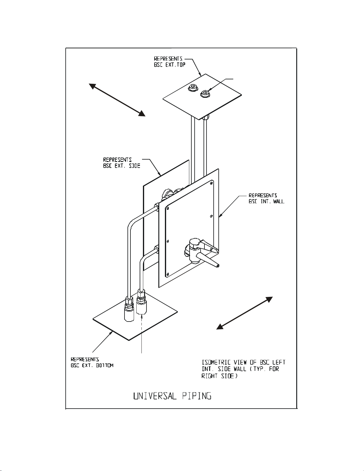
Service Valves - Two service valves are standard with each cabinet. These valves are located
on the right and left side of the workstation and can be coded with the type of service that
they supply. Identification index buttons are supplied.
The cabinet supports four service valves. Additional valves may be purchased from Forma
Scientific.
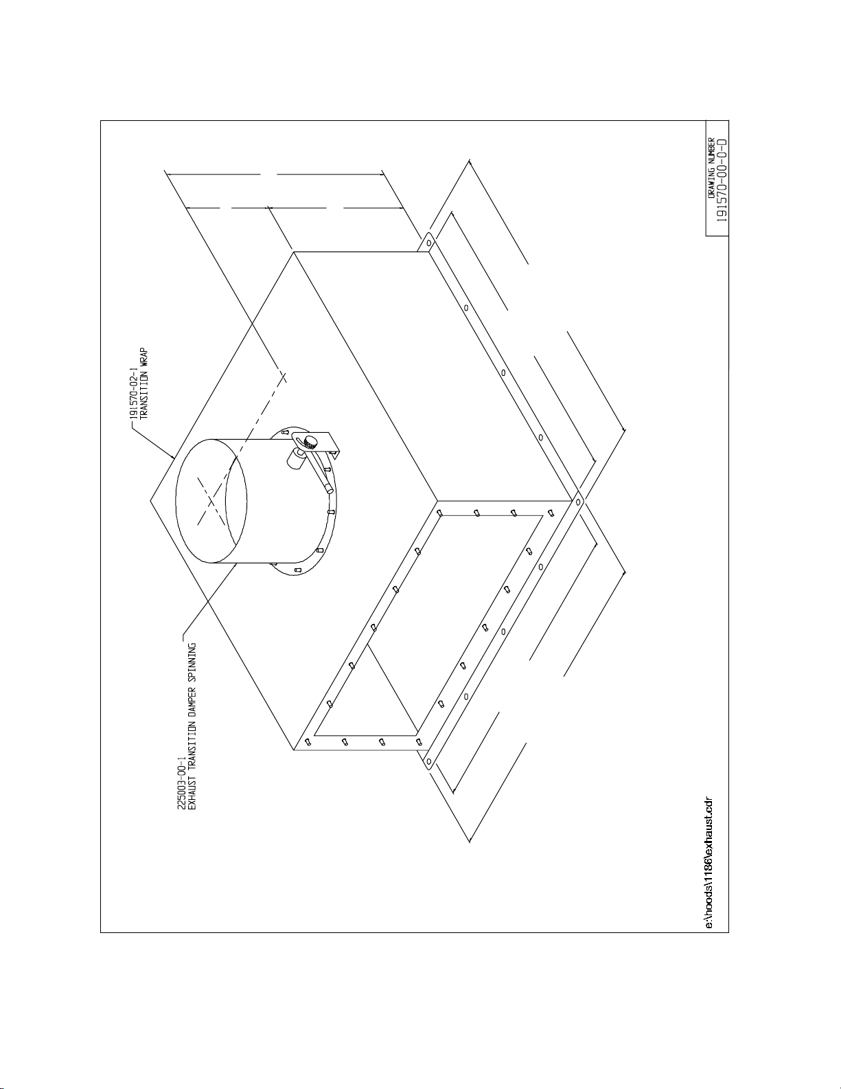
Exhaust Filter Guard - The exhaust filter guard, located on top of the exhaust filter,
protects the exhaust airflow and prevents the storage of objects on top of the housing.
Sliding Window Assembly - The sliding window assembly allows the operator to raise the
glass window to place items within the work area. If the sliding window is above the 10-inch
level, a red light and audible alarm warns that an unsafe condition exists.
When work is being performed in the cabinet, the sliding window must be at
the 10-inch position to avoid contamination to product and personnel.

FormaModel 1280/1290 Series _________________________________General Cautions
5-1
Section 5 - General Cautions
5.1 Caution Notes
•Following initial installation, the unit must be thoroughly tested and certified.
•All activities to be performed within the cabinet should be approved by a biological
safety officer or other qualified individual.
•Since the HEPA filters remove particulates only (not gas), explosive/flammable
substances should never be used in the cabinet, unless approved and monitored by a
biological safety officer or other qualified individual.
•Ultra-violet lighting should not be used while personnel are using the cabinet. If
exposure cannot be avoided, the proper safety gear/clothing must be worn. Consult a
biological safety officer or other qualified individual for proper procedures.
•If the cabinet is to be used for biological or toxicological applications, a biological
safety officer or other qualified individual must monitor it.
•If the unit needs to be serviced, it must be decontaminated to protect service personnel
from contamination. After servicing, the cabinet must be recertified by a qualified
certifying agency.
•None of the perforations in the work area may be covered or blocked, as airflow will be
disrupted and contamination may occur.
•Paper catches should always be kept free of debris.

FormaModel 1280/1290 Series ________________________________________Start-Up
6-1
Section 6 - Cabinet Start-Up
6.1 General Recommendations
•Keep movement in the room to a minimum when the cabinet is in use.
•Keep all laboratory doors closed to prevent drafts that may disturb critical airflow.
•Pre-plan cabinet use and place everything needed in the cabinet so that nothing passes
through the air barrier (in or out) during the procedure.
•Practice good aseptic technique to ensure safe use of the cabinet.
•If a spill occurs, clean it up immediately. Decontaminate the work area and all affected
equipment.
•Do not cover or block the exhaust grille.
•Do not cover or block any perforations (air holes) in the work area.
6.2 Use of Auxiliary Equipment in the Cabinet
Use auxiliary equipment in the cabinet only if proper precautions are taken. Appliances
used in the work area will cause turbulence, disturb the airflow and need to be carefully
managed. The equipment should be placed at the rear of the workspace where it will have
minimal effect.
A blender may be used in the cabinet. But because of the amount of aerosol it produces
and the turbulence it causes, it is recommended that it be removed from the cabinet as soon
as possible.
6.3 Cabinet Checklist
•Verify that the Drain valve is closed (the handle turned horizontal).
•Verify that all service valves are closed.
•Verify that the cardboard exhaust filter protector has been removed.

FormaModel 1280/1290 Series ________________________________________Start-Up
6-2
6.4 Start-Up Procedure
•Turn the light on.
•Check the intake and exhaust grilles to ensure they are not blocked.
•Turn the blower on.
•Place everything needed into the cabinet.
•Place the viewing window at 10 inches.
Other manuals for 1284
2
This manual suits for next models
6
Table of contents
Other Forma Scientific Laboratory Equipment manuals

Forma Scientific
Forma Scientific 1284 User manual

Forma Scientific
Forma Scientific 1184 User manual

Forma Scientific
Forma Scientific 3940 Operating instructions

Forma Scientific
Forma Scientific 3911 User manual

Forma Scientific
Forma Scientific ThermoQuest 3110 Series Operating instructions

Forma Scientific
Forma Scientific 1184 User manual

Forma Scientific
Forma Scientific 3920 User manual

Forma Scientific
Forma Scientific 1184 User manual

Forma Scientific
Forma Scientific 8172 User manual

Forma Scientific
Forma Scientific 1122 User manual