Forma Scientific 3911 User manual
Forma Scientific, Inc.
P.O. Box 649
Marietta, Ohio 45750
U.S.A. Telephone: (740) 373-4763
Telefax: (740) 373-4189
Model: 3911/3913
Reach-In
Incubator
11
cu
ft
capacity
Manual No. 7013911 Rev-3
IMPORTANT!
Read This Instruction Manual
Failure to read, understand and follow the instructions in this manual may result in
damage to the unit, injury to operating personnel and poor equipment performance.
Caution:
All
internal adjustments andmaintenance
must
be performedby
qualifiedservice personnel.
Refer to the serial tag on the
rear cover
of
this manual
-------------------------------------------------------
Fonna
Scientific, Inc.
CAUTION
Contains
Parts
and
Assemblies
Susceptible
to
Damage
by
Electrostatic
Discharge
(ESD)
NOTE:
The material in this manual is for information purposes only. The contents and the
product it describes are subject to change without notice. Forma Scientific, Inc. makes no
representations or warranties with respect to this manual. In no event shall Forma
Scientific, Inc. be held liable for any damages, direct or incidental, arising out
of
or
related to the use
of
this manual.
This product is not intended for any use(s) other than the use(s) described in the
labeling or this user's manual.
MANUAL NO. 7013911 I
3 18192 4/20/99 Updated Figure
5-1
wiring per
G.
Smith ccp
2 17725/IN-2436 10/6/98 Add sections 2.9 and 3.5 per ECR deg
1 IN-2111 8/96 Product release (2) add Watlow 982 deg
REV
ECN
DATE DESCRIPTION By
11

Forma Scientific,
111
Forma Scientific,
Inc.
___________________________
Service
Do You Need Information or Assistance on Forma Scientific
Products?
If
you do, please contact us
8:00
a.m. to
7:00
p.m. (Eastern Time) at:
1-740-373-4763
Direct
1-800-848-3080
Toll
Free, U.S. and Canada
1-740-373-4189
FAX
------I·-----.nttp:77www.fo:::cr:::::m:::-:a::-.-:::-co:::cm=------.I=ntL.:e:-=rn:::-:e::-LtWOrlClwiCleWelJRome Page
Forma's Sales Support can provide information on pricing and give you quotations.
We
can take your order and provide delivery information on major equipment items or make
arrangements to have your local sales representative contact you. Our products are listed on the
Internet and we can be contacted through our Internet home page.
The Forma Product Service Support can supply technical information about proper
------l
__
---l>Ietuf>;-*}pemtiGIl-Qr-
troubleshg~q~an
fill
yom:-needs-.,fuf..,l;p~..(Jf-----+-----~
replacement parts or provide you with on-site service.
We
can also provide you with a quotation
on our Extended Warranty for your Forma products.
Whatever Forma products you need or use, we will be happy to discuss your applications.
If
you are experiencing technical problems, working together,
we
will help you locate the
problem and, chances are, correct it
yourselLover
the telephone without a service call.
When more extensive service is necessary, we will assist you with direct factory trained
technicians or a qualified service organization for on-the-spot repair.
If
your service need
is
covered by the Forma warranty, we will arrange for the unit to
be
repaired at our expense and to
your satisfaction.
Regardless
of
your needs, Forma's professional telephone technicians are available to
assist you Monday through Friday from 8:00 a.m. to 7:00 p.m. Eastern Time. Please contact us
by telephone or fax.
If
you wish to write, our mailing address is:
Forma Scientific, Inc.
PO Box 649
Marietta,
OB
45750
International customers please contact your local Forma Scientific distributor.
iii

Forma
Scientific,
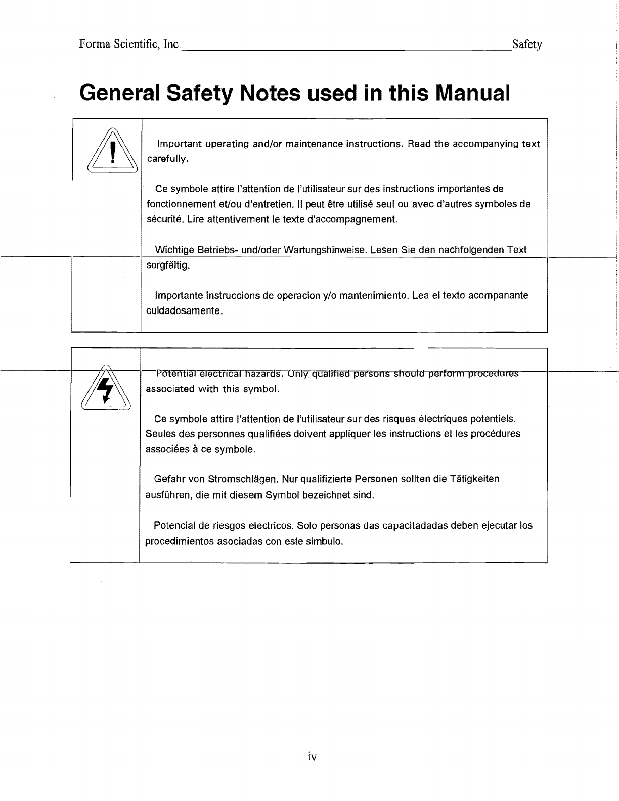
General Safety Notes used
in
this Manual
Important operating and/or maintenance instructions. Read the accompanying
text
carefully.
Ce symbole attire I'attention de "utilisateur sur des instructions importantes de
fonctionnement
eUou
d'entretien.
II
peut etre utilise seul
ou
avec
d'autres symboles de
securite. Lire attentivement
Ie
texte d'accompagnement.
Wichtige 8etriebs- und/oder Wartungshinweise. Lesen Sie den nachfolgenden Text
sorgfaltig.
Importante instruccions de operacion y/o mantenimiento. Lea el texto acompanante
cuidadosamente.
associated
with
this symbol.
Ce
symbole attire I'attention de I'utilisateur sur des risques electriques potentiels.
Seules des personnes qualifiees doivent appliquer les instructions et les procedures
associees ace symbole.
Gefahr von Stromschlagen. Nurqualifizierte Personen soliten die Tatigkeiten
ausfUhren, die
mit
diesem Symbol bezeichnet sind.
Potencial de riesgos electricos. Solo personas das capacitadadas deben ejecutar los
procedimientos asociadas con este simbulo.
IV
Forma Scientific, Inc.
__________________________
Safety
Equipment being maintained or serviced must
be
turned
off
and
locked
off
to
prevent possible injury.
Risques potentiels lies aI'energie. L'equipement
en
entretien
ou
en
maintenance doit
etre eteint et mis sous cle pour eviter des blessures possibles.
Ger~te,
an
denen Wartungs- oder Servicearbeiten durchgefOhrt werden, mussen
abgeschaltet und abgeschlossen werden,
um
Verletzungen
zu
vermeiden.
EI
equipo recibiendo servicio 0 mantenimiento debe ser apagado y segurado
para
prevenir danos.
;
A Hot surface(s) present which may cause burns to unprotected skin or
to
materials ,
which may
be
damaged by elevated temperatures
Presence de surface(s) chaude(s) pouvant causer des brOlures sur
la
peau
non
protegee,
ou
sur des matieres pouvant etre endommagees par des temperatures
elevees.
HeiBe
Oberfl~che(n)
konnen ungeschutzter Haut Verbrennungen
zufOgen
oder
Schaden
an
Materialien verursachen, die nicht
hitzebest~ndig
sind.
Superficias calientes que pueden causar quemaduras a pieI sin proteccion 0 a
materiales que pueden estar danados por elevadas temperaturas.
..J
Always use the proper protective equipment (clothing, gloves, goggles etc.).
..J
Always dissipate extreme cold or heat and wear protective clothing.
..J
Always follow good hygiene practices.
..J
Each individual is responsible for his or her own safety.
v
Forma Scientific,
Inc.,
______________________
Contents
Table
of
Contents
SECTION 1 - RECEIVING
1.1
Preliminary Inspection................................................................................
1-1
1.2 Visible Loss or Damage.............................................................................
1-1
1.3
Responsibility for Shipping Damage...........................................................
1-1
SECTION 2 - INSTALLATION AND START-UP
2.1
Location .....................................................................................................
2-1
2.2 Water (Humidity System) and Drain Connections........................................
2-1
a.
Connecting the Water Inlet for the Humidity System .............................
2-1
b.
Connecting the Drain Line .....................................................................2-2
2.3 RS-232 Output Interface and Remote Alarm Connector..............................2-3 '
..
a.
RS-232 Data Output.............................................................................2-3
b.
Remote Alarm Contacts........................................................................2-3
2.4 Power Connection .....................................................................................2-4
2.5 Start-Up Procedure.....................................................................................2-4
2.6 Setting the Overtemp Safety Thermostat....................................................2-4
2.7 Setting the Undertemp Safety Thermostat...................................................2-5
2.8 Preparing the optional CoBex Recorder ....................................................2-6
a.
Installing the Chart Recorder Battery ....................................................2-6
b.
Changing the Chart Paper .....................................................................2-6
c.
Changing the Pen ..................................................................................2-7
d.
Calibrating the chart recorder................................................................2-7
2.9 Offset Calibration.......................................................................................2-8
2.10 Controller Configuration..........................................................................2-11
Temperature Configuration
Humidity Configuration
SECTION 3 - CONTROL PANEL OPERATION
3.1 The 3911 Control Panel ...........................................................................
3-1
• Main
Power
Switch
and Indicator Light ..................................................3-1
• Refrigeration Switch and Indicator Light.................................................
3-1
'
Vl

Forma Scientific, Inc
..
______________________
Contents
• Defrost Switch and Indicator Light .........................................................3-2
• Overtemp Safety Control, Indicator Light and Audible Alarm................3-2
• Undertemp Safety Control, Indicator Light and Audible Alarm..............3-2
• Humidify Switch and Indicator Light.......................................................
3-3
• Dehumidify Switch and Indicator Light...................................................
3-3
• Audible Humidity Alarm and Indicator....................................................3-3
3.2 Setting the Incubator's Operating Temperature......................................3-4
3.3 Setting the Incubator's Operating Humidity............................................
3-5
3.4 Programming the controllers ...................................................................
3-5
the mechanicallockout......................................................3-5
a.
b.
Removing the software lockout .........................................................3-6
3.5 Air Exchange Ventilator Caps .................................................................3-8
SECTION 4 - ROUTINE MAINTENANCE
4.1 Cleaning the Incubator.............................................................................
4-1
________
""a'-.
'"""M"""a!±!.i~nt!:.!:!:!.aining
the Humidity Steam Generator.......................................
4-1
SECTION 5 -
SERVICE
5.1
Accessing the Electrical Components......................................................
5-1
5.2 Replacing the OvertemplUndertemp Probe and Thermostat...................
5-1
5.3 Replacing the Humidity/Temperature Sensor..........................................5-2
5.4 Replacing the Optional Recorder and Probe(s).......................................
5-3
5.5 Setting the
Door
Heater Control ..............................................................5-4
5.6 Cleaning and Adjusting the Humidity Steam Generator...........................5-5
a.
Checking
the
Steam Generator Safety Thermostat Calibration ..........5-6
SECTION 6 - SPECIFICATIONS
SECTION 7 - SPARE PARTS LISTS
SECTION 8 - SCHEMATICS
SECTION 9 - WARRANTY INFORMATION AND SUPPLEMENTS
VII

Forma Scientific,
SECTION 1 - RECEIVING
1.1 Preliminary Inspection
This item was thoroughly inspected
and
carefully packed prior to shipment
and
all
-------neGSSsary-pF6<.7autiens-weFe-t-aken-te-enSUFe-s-afe-aFFival-ef-the-meF<.7handise-at-if9-s
-----
destination. Immediately upon receipt, before the unit
is
moved from the receiving area,
carefully examine the shipment for loss or damage. Unpack the shipment and inspect
both interior and exterior for
any
in·transit damage.
1.2 Visible Loss or Damage
---------ff-any-loss
Ol-damage
is
discovered, note
any
discrepancies
OIl
the
dcl;..iv""'e
.....
ryrr-rI""'ecMe:rrjTTpt-L.-----:
Failure to adequately describe such evidence
of
loss or damage
may
result
in
the carrier
refusing to honor a damage
claim.
Immediately call the delivering carrier
and
request that
their representative perform
an
inspection. Do not discard
any
of
the packing material
and
under no circumstances move the shipment from the receiving area.
1.3 Responsibility for Shipping Damage
For products shipped F.O.B. Marietta, Ohio, the responsibility
of
Forma Scientific,
Inc. ends when the merchandise
is
loaded onto the carrier's vehicle.
On
F.O.B. Destination shipments, Forma Scientific's and the carrier's responsibility
en4s when your Receiving Department personnel sign a free
and
clear delivery receipt.
Whenever possible, Forma Scientific, Inc. will assist
in
settling claims for loss
or
in-
transit damage.
.
;\,
1-1

Forma Scientific,
Inc.
_____________
~
____
___"InstallationJSet-Up
Section 2 - Installation and Set-Up
2.1
Locati
on
Locate the unit
on
a
firm,
level
surface
in
an
area
of
minimum
ambient temperature
fluctuation. A minimum
of
three (3) inches
of
clearance
is
required at the rear
of
the
f--
______
~in'-"'c"'_'u"_"b'_"a""to""r'_'_.
-"T,-,h~i,,-s
-",space
is
necessary to allow adeguate air flow around the
refrig,=er:..::a=ti=o:.:;.:n'--
_____
-i
system.
2.2
Water
(Humidity
System)
and
Drain
Connections
a.
Connecting
the Water Inlet
for
the
Humidity
System
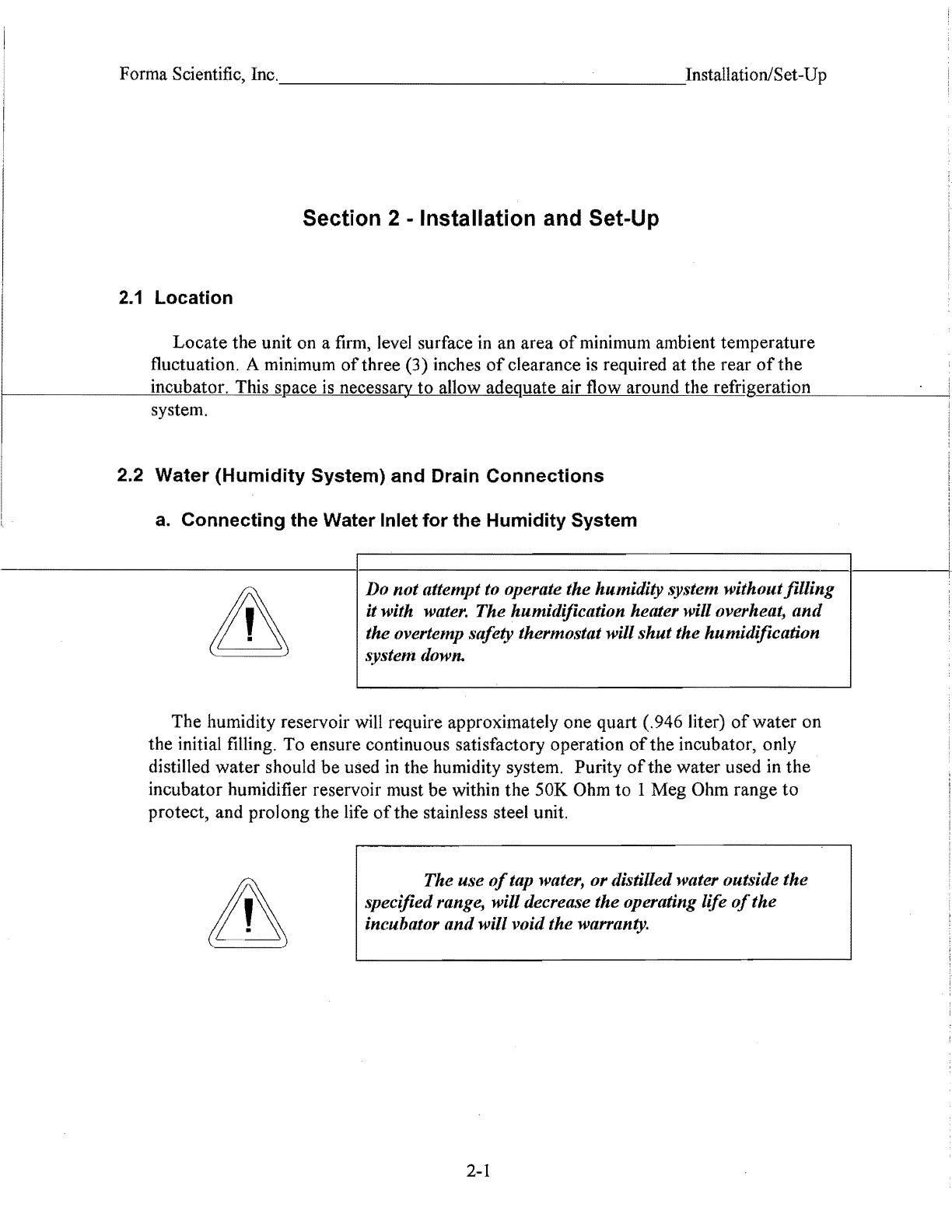
Do not attempt to operate the humidity system withoutfilling
it with water. The humidification heater will overheat,
and
the overtemp safety thermostat will shut the humidification
system down.
The humidity reservoir
will
require approximately one quart (.946 liter)
of
water on
the initial filling. To ensure continuous satisfactory operation
of
the incubator, only
distilled water should be used
in
the humidity system. Purity
of
the water used
in
the
incubator humidifier reservoir must be within the 50K
Ohm
to 1Meg Ohm range to
protect, and prolong the life
of
the stainless steel unit.
The use
of
tap water, or distilled water outside the
specifiedrange, will decrease the operating life
of
the
incubator
and
will void the warranty.
2-1
I

Forma Scientific, Inc.
___________________
-.:InstallationlSet-Up
The
water
inlet
is
the 1/8"
NPT
connection located on the rear top left corner
of
the
incubator. Water inlet pressure at the unit should be from
15
to 40 PSI. A manual shut-
off
valve should be installed between
the
main water supply and the incubator.
To
prevent mineral buildup on heater coils and humidity
generator walls, it may be necessary
to
clean the humidity
generator antI immersion heaters with a non-metallic
abrasive padandflush thoroughly every two or three months.
-----------------I-Re/er-to-8ection-4.2,Gleani-ng-the-Humidity-Generator-and-'-------'i
Immersion Heaters. !
b.
Connecting
the Drain Line
The cabinet's 3/8" MPT drain line connection is located on the rear (lower left side)
of
the
---------.c..mabi:Iret.
]\
P-trap
(Figure
2-1)
is
inclucled-wittn~be
installed
on
the
connection. To install the drain connection:
• Using Teflon pipe thread tape, tape the threads on the cabinet drain connection_
• Using
an
open end adjustable wrench, install the P-trap onto the connection. Make
sure that the trap is positioned down.
• Push a piece
of3/8"
ID
tubing onto the trap and direct the tubing to a convenient
drain. Install a hose clamp on the tubing,
if
desired.
To
cabinet drain
\ Figure
2-1
~§
Cabinet drain
P-trap
2-2

Forma
Scientific, Inc.
_________________
~_I.nstallationJSet-Up
2.3 Remote Data Output
a.
RS-232 Data Output
The Model 391113913 incubator is equipped with an RS-232 Serial Communication
Interface for the remote transmission oftemperature and humidity data. A terminal strip is located
on
the
back
of
the incubator for convenience. Refer to Figure 2-2 for terminal pin identification.
Terminal Strip Connections
0 0 0 0 0 0
-i
-i
;:0
() ()
z z
m 0 0 b h
(J) m
s:
s:
s:
~
0 0
-i
Z z
Temperature Humidity Remote Alarm
RS
232
RS
232 (Shown in alarm)
Figure 2-2
IMPORTANT USER
INFORMATION
Caution! Stored product should
be
protected by an activated alarm system
capable
of
initiating a timely response
24 hours/day. Forma Alarms provide
interconnect for centralized monitoring.
b. Remote Alarm Contacts
Remote alarm connections are also included on the terminal strip (Figure 2-2) providing
Normally Open (N.O.) and Normally Closed (N.C.) contacts. C
is
the Common terminal. The
remote alarm will activate when either the incubator's temperature or humidity go out
of
the set
alarm limits.
2-3
Forma Scientific,
2.4 Power Connection
The electrical junction box is located on the rear top section
of
the incubator. With
the
junction box switch OFF, connect the incubator to an adequate power source. See
the
electrical data plate mounted on the unit for electrical specifications.
2.5 Start-Up
When the humidification system is operational, the incubator may be started. Preset
the
controls as follows:
Overtemp Safety Thermostat......................... Fully Clockwise
Undertemp Safety Thermostat....................... Fully Counterclockwise
Main Power Switch.......................................ON
Humidity Controller......................................Desired Setpoint
Temperature Controller.................................Desired Setpoint
Door
Heater .................................................40% (factory set)
For
lre'st
overall performance
of
the
inculm:7'\l"",--rit'l>'F''iS'fTi7n;~I+mI'\"'"'V=i1i7'<1T-.:rh7'ITTtrHk-I:r---------+
turned on for most applications. When running
Low
or
No humidity at high
temperatures, the refrigeration switch may be turned off.
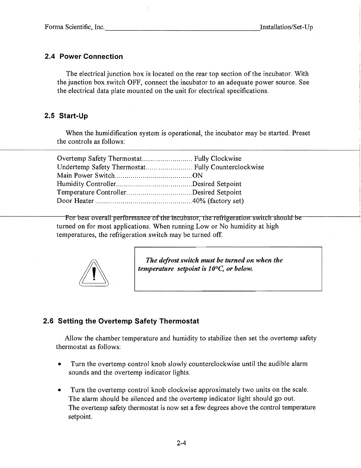
The defrost switch must be turned on when the
temperature setpoint is 10°C, or below.
2.6 Setting the Overtemp Safety Thermostat
Allow the chamber temperature and humidity
to
stabilize then set
the
overtemp safety
thermostat as follows:
• Turn the overtemp control knob slowly counterclockwise until
the
audible alarm
sounds and the overtemp indicator lights.
• Turn the overtemp control knob clockwise approximately
two
units on the scale.
The alarm should
be
silenced and the overtemp indicator light should go out.
The overtemp safety thermostat is now set a few degrees above the control temperature
setpoint.
2-4

---------------------------------------
Forma Scientific, Inc. Installation/Set-Up
When the chamber temperature rises to the overtemp control point, the alarm system will
activate, power
to
the heaters will shut off, and the chamber temperature will be
maintained at the overtemp control point.
When an overtemp condition occurs,
the
cause must be determined and corrected
before normal operation under the main temperature controller can be resumed.
Note: When the chamber temperature control setpoint is changed,
the
overtemp
safety thermostat must be reset
to
accommodate
the
change.
2.7 Setting the Undertemp Safety Thermostat
Allow the cHamber temperature anonumiOity to staoiliZe1J:1en
setme
undertemp
safety thermostat as follows:
• Turn
the
undertemp control knob slowly clockwise until
the
audible alarm sounds
and
the
undertemp indicator lights.
• Turn the undertemp control knob counterclockwise approximately
two
units on the
scale. The alarm should be silenced and the indicator light should go out.
The undertemp safety thermostat is now set a few degrees below the control
temperature setpoint. When the chamber temperature drops to
the
undertemp control
point, the alarm system will activate, power
to
the compressor will shut off, and the
chamber temperature will be maintained at the undertemp control point.
When an undertemp condition occurs,
the
cause must
be
determined and corrected
before normal operation under
the
main temperature controller can
be
resumed.
Note: When
the
chamber temperature control setpoint is changed, the undertemp
safety thermostat must
be
reset
to
accommodate
the
change.
2-5
Forma Scientific, Inc.
____________
~
______
-InstallationJSet-Up
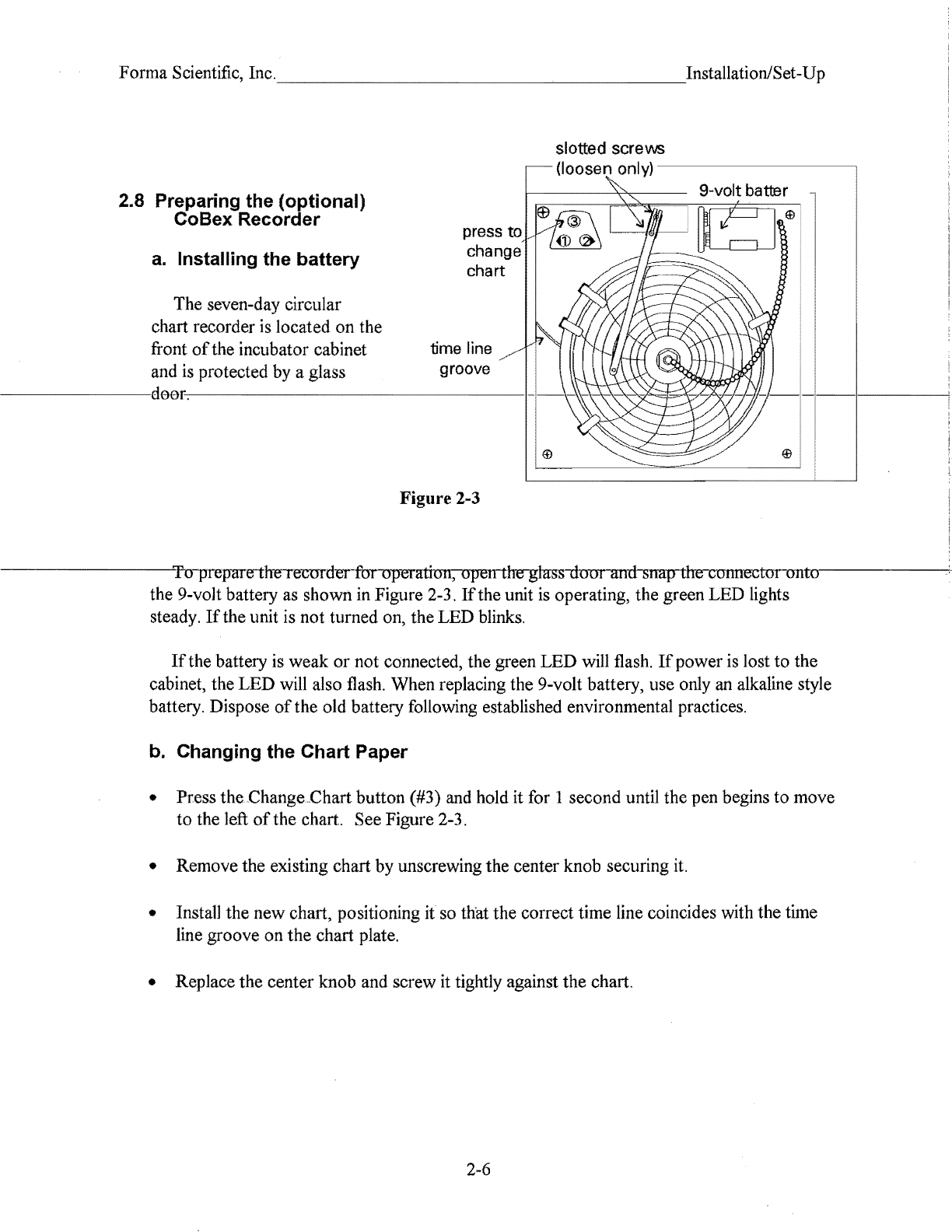
2.8 Preparing the (optional)
CoBex Recorder
a.
Installing the battery
The seven-day circular
chart recorder is located on the
front
of
the incubator cabinet
and is protected by a glass
slotted screvvs
(loosen only)
--------------,
press
to
change
chart
time line
groove
9-volt batter
Figure 2-3
To
plepme the IecmdeI furuperntiuII, open the glass
dom
and snap the
connectunmtrro--------+
the 9-volt battery as shown
in
Figure 2-3.
If
the unit is operating, the green LED lights
steady.
Ifthe
unit is not turned on, the LED blinks.
If
the battery is weak
or
not connected, the green
LED
will flash.
If
power is lost
to
the
cabinet, the
LED
will also flash. When replacing the 9-volt battery, use only
an
alkaline style
battery. Dispose
of
the old battery following established environmental practices.
b.
Changing the Chart Paper
• Press the.Change.Chart button (#3) and hold it for 1 second until the pen begins
to
move
to
the left
of
the chart. See Figure 2-3.
• Remove the existing chart
by
unscrewing the center knob securing it.
• InstaU the new chart, positioning
it
so that the correct time line coincides with the time
line groove
on
the
chart plate.
• Replace the center knob and screw it tightly against the chart.
2-6
Forma Scientific, Inc.
___________________
-eInstallationlSet-Up
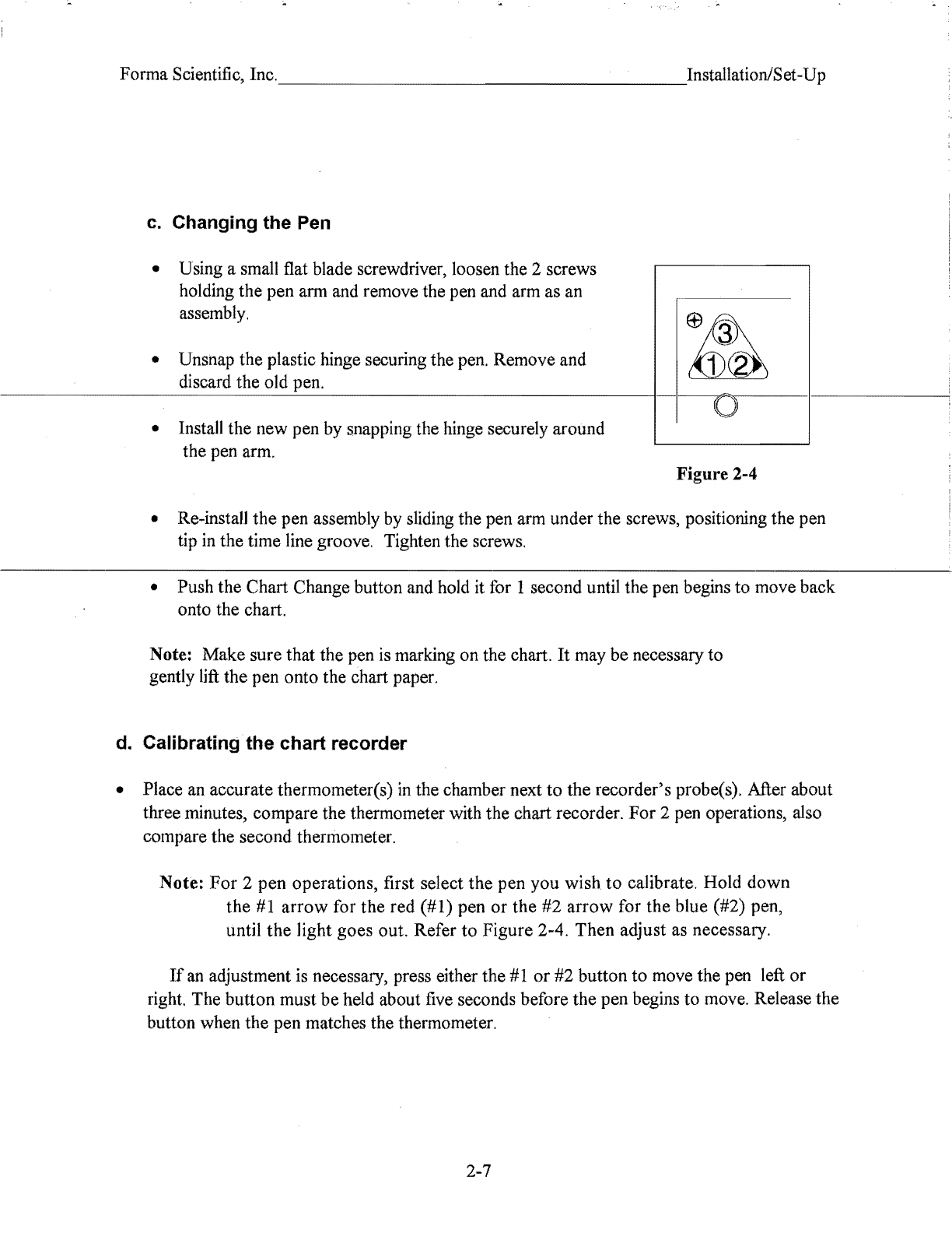
c.
Changing the Pell
• Using a small flat blade screwdriver, loosen the 2 screws
holding the pen arm and remove the pen and arm as an
assembly.
• Unsnap the plastic hinge securing the pen. Remove and
1(2)
~
discard the old pen. ,
• Install the new pen by snapping the hinge securely around
the pen arm. Figure 2-4
• Re-instaH the pen assembly by sliding the pen arm under the screws, positioning the pen
tip
in
the time line groove. Tighten the screws.
• Push the Chart Change button and hold it for 1 second until the pen begins to move back
onto the chart.
Note: Make sure that the pen
is
marking on the chart.
It
may be necessary to
gently lift the pen onto the chart paper.
d. Calibrating the chart recorder
• Place an accurate thermometer(s)
in
the chamber next
to
the recorder's probe(s). After about
three minutes, compare the thermometer with the chart recorder.
For
2 pen operations, also
compare the second thermometer.
Note:
For
2 pen operations, first select the pen you wish
to
calibrate. Hold down
the
#1
arrow
for the red (#1) pen
or
the
#2 arrow for the blue (#2) pen,
until
the
light goes out. Refer
to
Figure 2-4. Then adjust as necessary.
If
an
adjustment is necessary, press either the
#1
or #2 button to move the pen left
or
right. The button must
be
held about five seconds before the pen begins to move. Release the
button when the pen matches the thermometer.
2-7
Forma Scientific, Inc.
_____
~
____________
___"InstallationiSet-Up
2.9 Offset Calibration
•
It
may
be
necessary to calibrate the temperature
or
humidity controllers to match an
independent temperature
or
humidity sensor.
To
do so, follow the next few steps.
• Suspend an independent, calibrated sensor(s)
in
the center
ofthe
interior chamber.
• Allow approximately 30 minutes for the incubator
to
stabilize.
•
Tum
off
the main power switch.
• Wear a grounding wrist strap to avoid damaging any
of
the electrical components.
• Remove
the
982 controller module(s) by pressing in
the
four retaining tabs,
two
on
the
right side,
two
on
the left side. (Refer to Figure 2-5) Pull the controller module out by
gently rocking it from side
to
side.
• Looking at
the
top and left side
of
the controller module, locate the red DIP switches
indicated in Figure 2-6. Use your fingernail
or
a small screwdriver, to
tum
offSW
2 by
-------~rneving-t_he_white_teggle_rewafds-the-frent-of-the-rneclule
as
shewi1-i:fl-the-tlltlst-mt-ieur.-.
---------c
• Return the controller into its frame and firmly press on the top and bottom
of
the bezel
until
all
four locking tabs "click" into place.
•
Tum
on the main power switch.
• Press the
Up
and Down Arrow keys simultaneously for 3 seconds. The word "InPt" will
appear
in
the upper display, and "set" will appear in the lower display.
• Press the
Down
Arrow once, then continue to press the
Mode
key until "LOC" appears
in
the lower display. The upper display will show
2.
Press
the
Down Arrow until 0
appears.
• Press the
Mode
key once, then the Up Arrow once.
"lnPt"
will appear
in
the upper display,
and "set" will
be
in
the lower display. Press the
Mode
key until "CAL
1"
appears in the
lower display. Press the Up
or
Down Arrow key
to
either add
or
subtract an offset value.
This would be the difference between the actual value shown on the controller, and
the
reference sensor value.
• Press the Display key once.
• Press the
up
and down keys simultaneously for 3 seconds. The word "lnPt" will appear
in the upper display, and "set" will appear
in
the lower display.
2-8
Forma Scientific, Inc.
____________________
Installation/Set-Up
• Press the down arrow once, then continue to press the mode key until "LOC" appears in
the lower display. The upper display will show
O.
Press the up arrow until 2 appears.
• Press the display key once
•
Tum
off
the main power switch.
• Wear a grounding wrist strap to avoid damaging any
of
the
electrical components.
• Remove the 982 controller module(s) by pressing
in
the four retaining tabs, two
on
the
f---
_______
~right
side, two on the left side. (Refer to Figure 2-5) Pull the controller module out by
_____
----;
gently rocking it from side to side.
• Looking at the top and left side
of
the controller module, locate the red DIP switches
indicated in Figure 2-6. Use your fingernail
or
a small screwdriver, to
tum
on
SW 2 by
moving
the
white toggle towards the rear
of
the module as shown.
• Return the controller into its frame and firmly press on the top and bottom
of
the bezel
-----------:-:u=nt~il·
all
four locKing taos
*C11CK"
into place.
Press Press
•
Tum
on the main power switch.
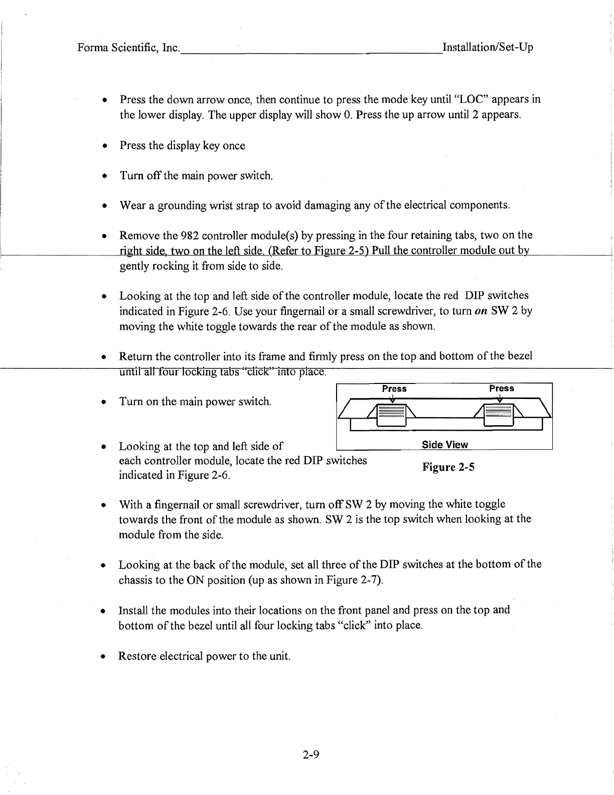
• Looking at the top and left side
of
Side View
each controller module, locate the red DIP switches Figure 2-5
indicated in Figure 2-6.
• With a fingernail
or
small screwdriver,
tum
off
SW 2 by moving the white toggle
towards the front
of
the module as shown. SW 2 is the top switch when looking at the
module from the side.
• Looking
at
the back
of
the module, set all three
of
theDIP switches at the bottom
of
the
chassis
to
the
ON
position (up as shown in Figure 2-7).
• Install the modules into their locations on the front panel and press on the
top
and
bottom
of
the bezel until
all
four locking tabs "click" into place.
• Restore electrical power
to
the unit.
2-9
Other manuals for 3911
5
This manual suits for next models
1
Table of contents
Other Forma Scientific Laboratory Equipment manuals

Forma Scientific
Forma Scientific 1284 User manual

Forma Scientific
Forma Scientific 3911 User manual

Forma Scientific
Forma Scientific 3940 Operating instructions

Forma Scientific
Forma Scientific 1284 User manual

Forma Scientific
Forma Scientific 8172 User manual

Forma Scientific
Forma Scientific 3911 User manual

Forma Scientific
Forma Scientific 1184 User manual

Forma Scientific
Forma Scientific 1284 User manual

Forma Scientific
Forma Scientific 3911 User manual

Forma Scientific
Forma Scientific 1184 User manual


