Formula 151239 Series User manual
1
Ø39 Trial Fork
User Manual –
This user manual contains all the relevant information regarding the correct use and
maintenance of the Forks: Trial Racing Steel, Trial Ø39 4Ride, Trial Racing Aluminium, Trial
Racing Pro Steel, Trial Racing Pro Aluminium, Trial Racing Pro Kashima

2
Index
Important Information and Maintenance Intervals: .........................................................................................3
Maintenance Intervals ...........................................................................................................................................3
Oil Level Sheet........................................................................................................................................................4
Required Tools .......................................................................................................................................................6
Fork Settings...........................................................................................................................................................7
Extension setting ..................................................................................................................................................7
Compression setting (only on some models).....................................................................................................7
End stroke setting.................................................................................................................................................7
Spring preload setting ..........................................................................................................................................7
Cleaning the Dust Seals........................................................................................................................................8
Oil Change Left Leg...............................................................................................................................................9
Oil Change Left Leg.............................................................................................................................................12
Seals Replacement Left Leg ..............................................................................................................................15
Seals Replacement Right Leg............................................................................................................................20
3
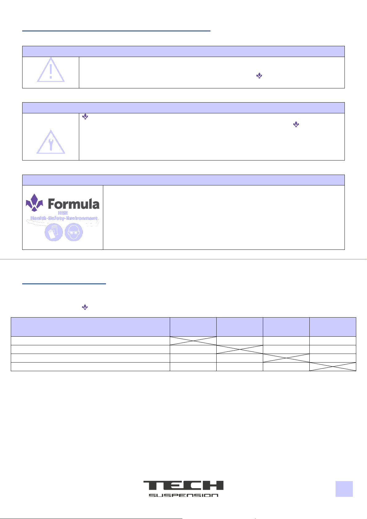
Important Information and Maintenance Intervals:
IMPORTANT
Repeatedly using our products in extreme conditions requires more frequent servicing.
Using unrecommended high-pressure washing methods, using unrecommended
spare parts, solvents and lubricants not recommended by Formula reduce the life
span of our products.
IMPORTANT
Formula recommends only ORIGINAL spare parts and lubricant products
Do not attempt assembly and disassembly operations on this product. Formula
recommends consulting servicing technicians for these activities and finding eventual
cracks, deformations, or evidence of damage due to fatigue or wear: if the inspection
shows the presence of such problems, even if minor, immediately replace the
component –with no attempts of repair.
SAFETY INFORMATION
Always wear nitrile gloves and safety glasses when working on the fork.
Ensure correct disposal of waste materials and liquids.
Maintenance Intervals
To keep the fork efficient during normal usage and ensure proper maintenance, follow the maintenance
intervals chosen by Formula:
Procedure
Before and
After any use
Every 8 Hours
1 Month
Every 35 Hours
3 Month
Every 100 Hours
1 Year
Washing with water and mild soap. Visual inspection.
Cleaning dust seals (if dust or mud is present)
Oil change
Full inspection
4
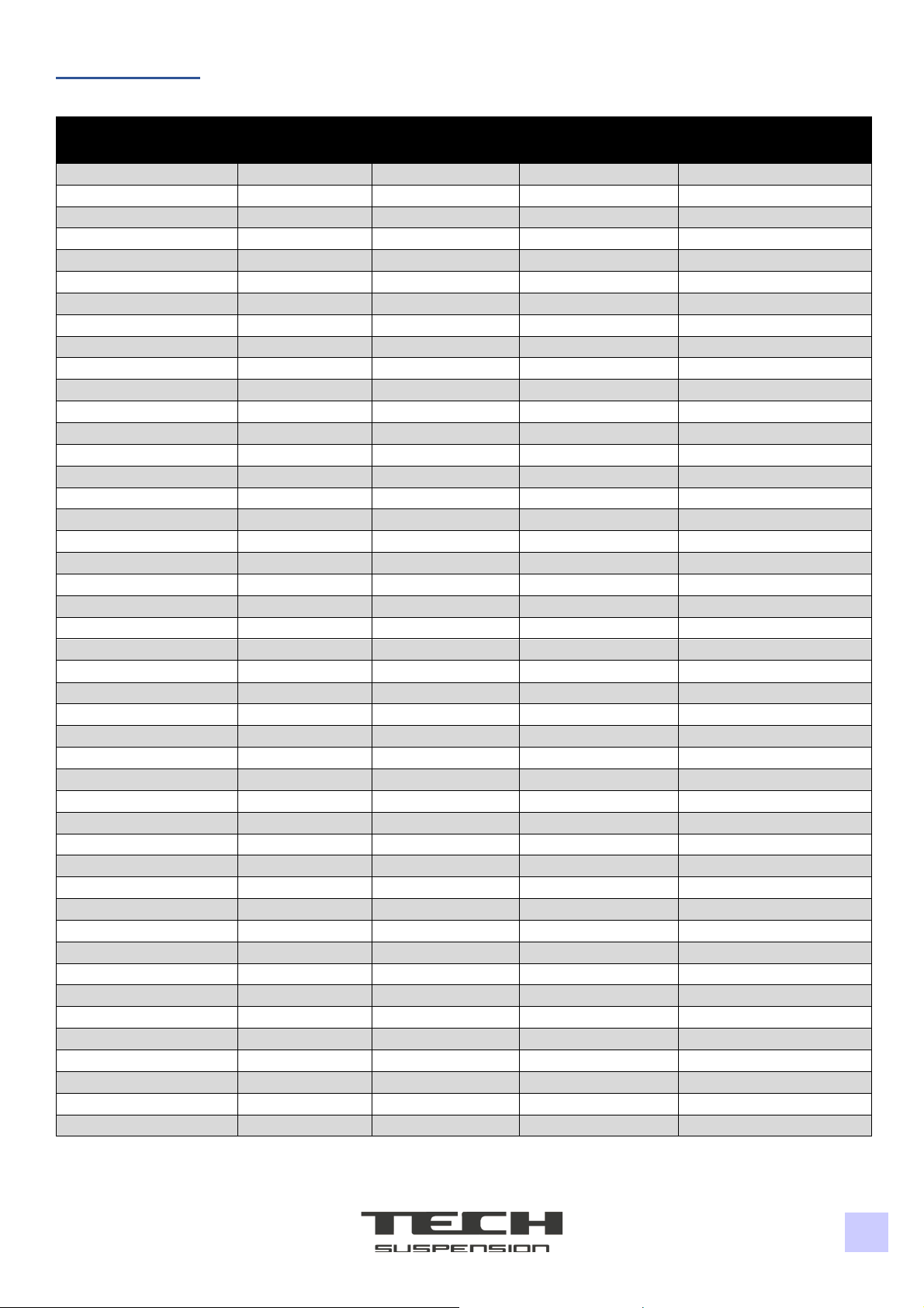
Oil Level Sheet
Fork Code
151239XXX
SX/Left (mm)
DX/Right (mm)
MY
Customer
000
118,0
118,0
2019 - 2022
Ø39 Standard
031
110,0
55,0
2011 - 2014
Beta
051
110,0
55,0
2011 - 2017
Sherco
054
130,0
75,0
2014
Sherco
055
130,0
75,0
2016
Sherco
056
130,0
75,0
2016
Sherco
057
130,0
75,0
2018
Sherco
058
130,0
75,0
2020
Sherco
059
140,0
85,0
2022
Sherco
101
110,0
55,0
2012
Jotagas
111
110,0
55,0
2012
Gas Gas
113
130,0
75,0
2014 - 2015
Jotagas
113
130,0
75,0
2013 - 2015
Gas Gas
113
130,0
75,0
2014 - 2015
Ossa
116
130,0
75,0
2016
Gas Gas
116
130,0
75,0
2017
Sherco
116
130,0
75,0
2017
Scorpa
119
130,0
75,0
2016
Gas Gas
121
100,0
50,0
2014
Honda
122
125,0
70,0
2014
Honda
123
100,0
50,0
2015
Honda
125
100,0
50,0
2016
Honda
127
125,0
60,0
2016
Honda
128
100,0
50,0
2017
Honda
129
130,0
70,0
2017
Honda
151
130,0
75,0
2015
Vertigo
152
130,0
75,0
2015
Vertigo
153
130,0
75,0
2016
Vertigo
154
130,0
75,0
2019
Vertigo
155
130,0
75,0
2019
Vertigo
156
130,0
75,0
2020
Vertigo
157
130,0
75,0
2020
Vertigo
158
130,0
75,0
2021
Vertigo
159
130,0
75,0
2021
Vertigo
171
130,0
75,0
2015
TRS
173
130,0
75,0
2017
TRS
174
130,0
75,0
2017
TRS
175
110,0
55,0
2018
TRS
176
110,0
55,0
2019
TRS
177
130,0
75,0
2020
TRS
178
110,0
55,0
2021
TRS
179
130,0
75,0
2021
TRS
185
130,0
75,0
2020
Electric Motion
186
130,0
75,0
2020
Electric Motion
187
118,0
118,0
2023
Electric Motion
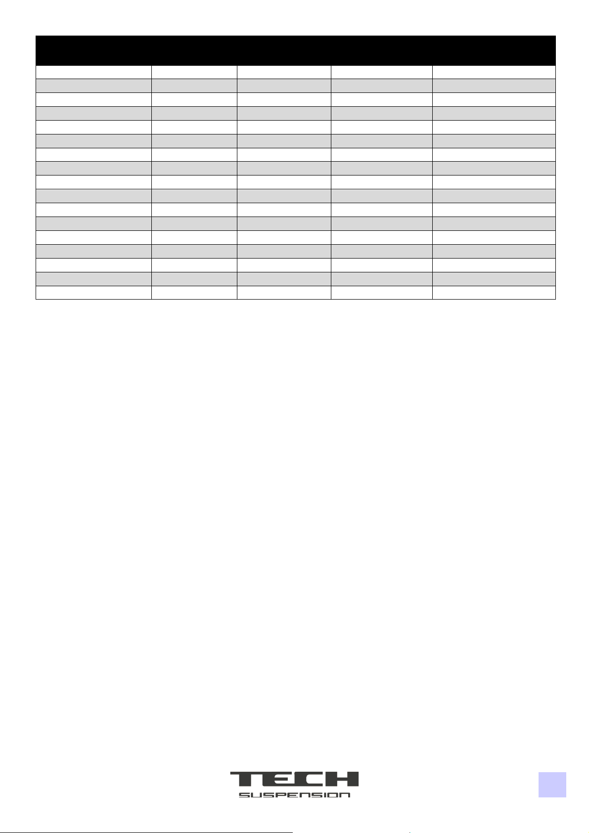
5
Fork Code
151239XXX
SX/Left (mm)
DX/Right (mm)
MY
Customer
200
130,0
75,0
2017
Gas Gas
202
130,0
75,0
2020
Gas Gas
203
130,0
75,0
2020
Gas Gas
204
125,0
70,0
2022
Gas Gas
205
125,0
70,0
2022
Gas Gas
207
125,0
70,0
2022
Gas Gas
231
125,0
70,0
2018
Honda
232
100,0
50,0
2018
Honda
233
130,0
70,0
2020
Honda
234
125,0
60,0
2022
Honda
250
2020
TRS
260
130,0
75,0
2022
Arctic Leopard
261
130,0
75,0
2022
Arctic Leopard
262
130,0
75,0
2022
Arctic Leopard
992
130,0
75,0
2022
Aftermarket
993
130,0
75,0
2023
Aftermarket
994
130,0
75,0
2023
Aftermarket

6
Required Tools
Description
Position
Q.ty
Part number
Bushing and Oil Seal Tool
1
1
0800DU007
Stanchion Tube Tool
2
1
080004000
Cartridge Assembly Tool
3
1
080008000
▪Bench vise;
▪Wrench key - 14 mm, 17 mm;
▪Hex key - 1,5 mm, 12 mm;
▪Flathead screwdriver;
▪Torque wrench;

7
Fork Settings
The forks have different settings to fine-tune their performance based on the rider’s needs. Settings adjustments
must be performed by an experienced technician. Setting a fork improperly could make the bike hard to ride and
could cause severe or fatal injuries.
Extension setting
Tools:
Flathead screwdriver.
Procedure:
The extension setting is located on the cap of the right leg. Turning the regulator clockwise will lower the
rebound speed; Turning the regulator anti-clockwise will increase the rebound speed. Usually, the
regulation is done by starting in a fully clockwise position and then turning anti-clockwise the regulator
between 16 and 22 clicks, depending on the temperature outside.
Compression setting (only on some models)
Tools:
Hex key 2 mm.
Procedure:
The compression setting is located on the lower screw of the right leg. This setting controls progressively
through the entirety of the compression stroke. Usually, starting with the regulator fully screwed you need to
unscrew the regulator by 2-3 turns (1 turn equals 360°).
End stroke setting
Tools:
Hex key 2 mm.
Procedure:
The end stroke setting is located on the lower screw of the left leg. This setting only affects the last 45 mm
of the stroke. Usually, the regulator is kept in a fully closed position. If the rider is light and unable to reach
the end stroke, the regulator can be turned anti-clockwise.
Spring preload setting
Tools:
Flathead screwdriver.
Procedure:
The spring preload setting is located on the cap of the left leg. This setting allows to increase the preload
up to 10 mm is a very personal setting. We suggest starting with the preload set halfway (fully screwed and
then unscrewed by 5 turns) and then regulating it by one turn at a time to obtain the ideal setting.
8
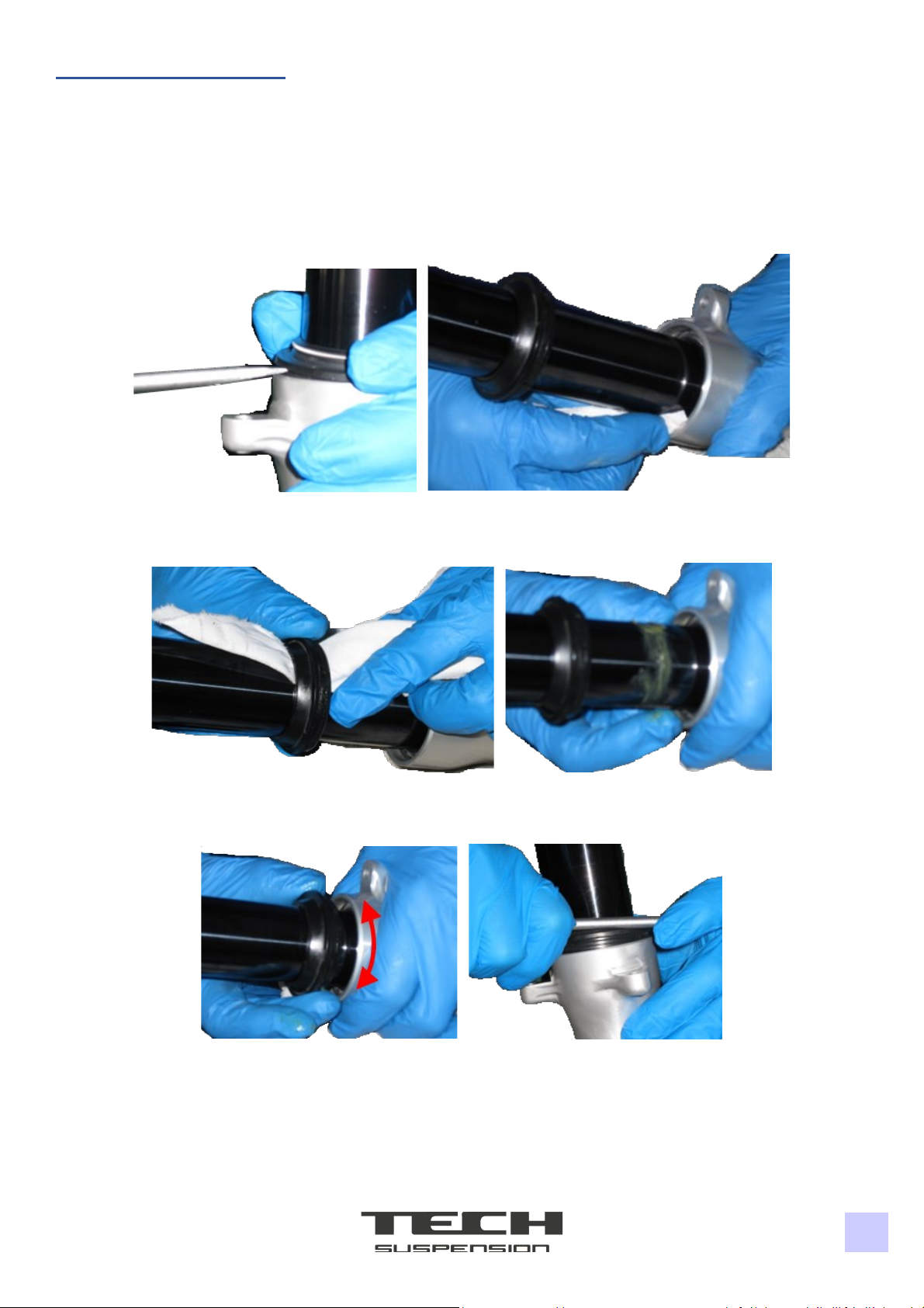
Cleaning the Dust Seals
Tools:
Flathead screwdriver, microfiber cloth.
Procedure:
1. Before proceeding accurately clean the fork;
2. Remove the dust seal by leveraging on its side with a flat-head screwdriver. Remove any dirt residue from the
dust seal and the oil seal with a microfiber cloth;
3. Insert a microfiber cloth inside the dust seal to remove dirt residue from the internal diameters, then apply
grease on the tube;
4. Rotate the dust seal on the grease and insert the dust seal in its housing by pushing on its outer diameters with a
screwdriver;
-End of Procedure-

9
Oil Change Left Leg
Tools:
Description
Position
Part number
Stanchion Tube Tool
2
080004000
Combined wrench 17 mm, Hex key 12 mm
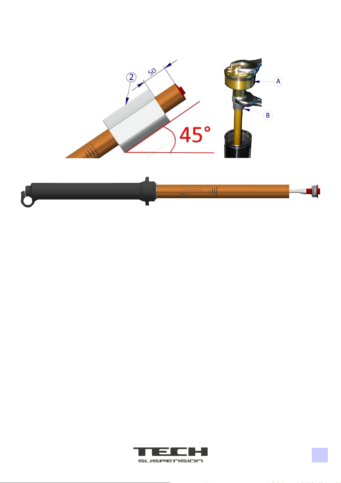
Procedure:
1. Before proceeding accurately clean the fork;
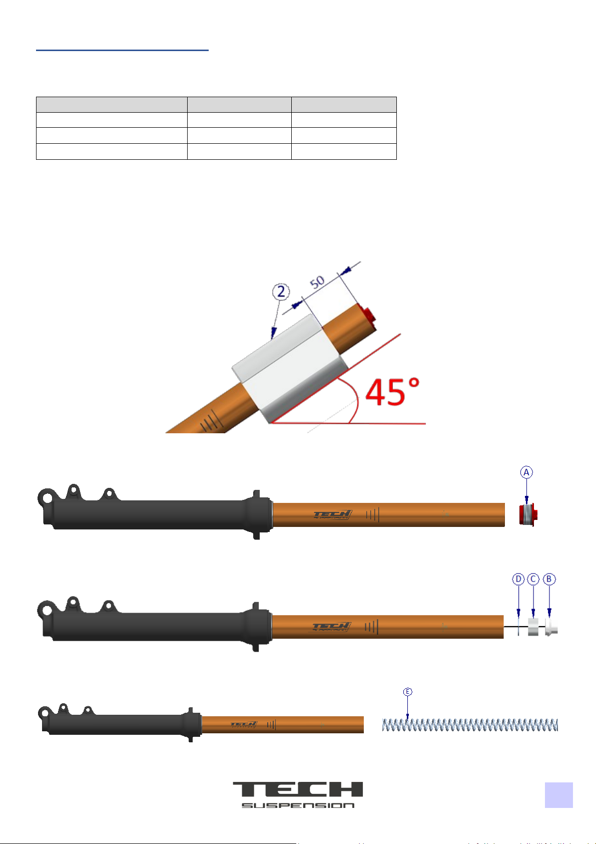
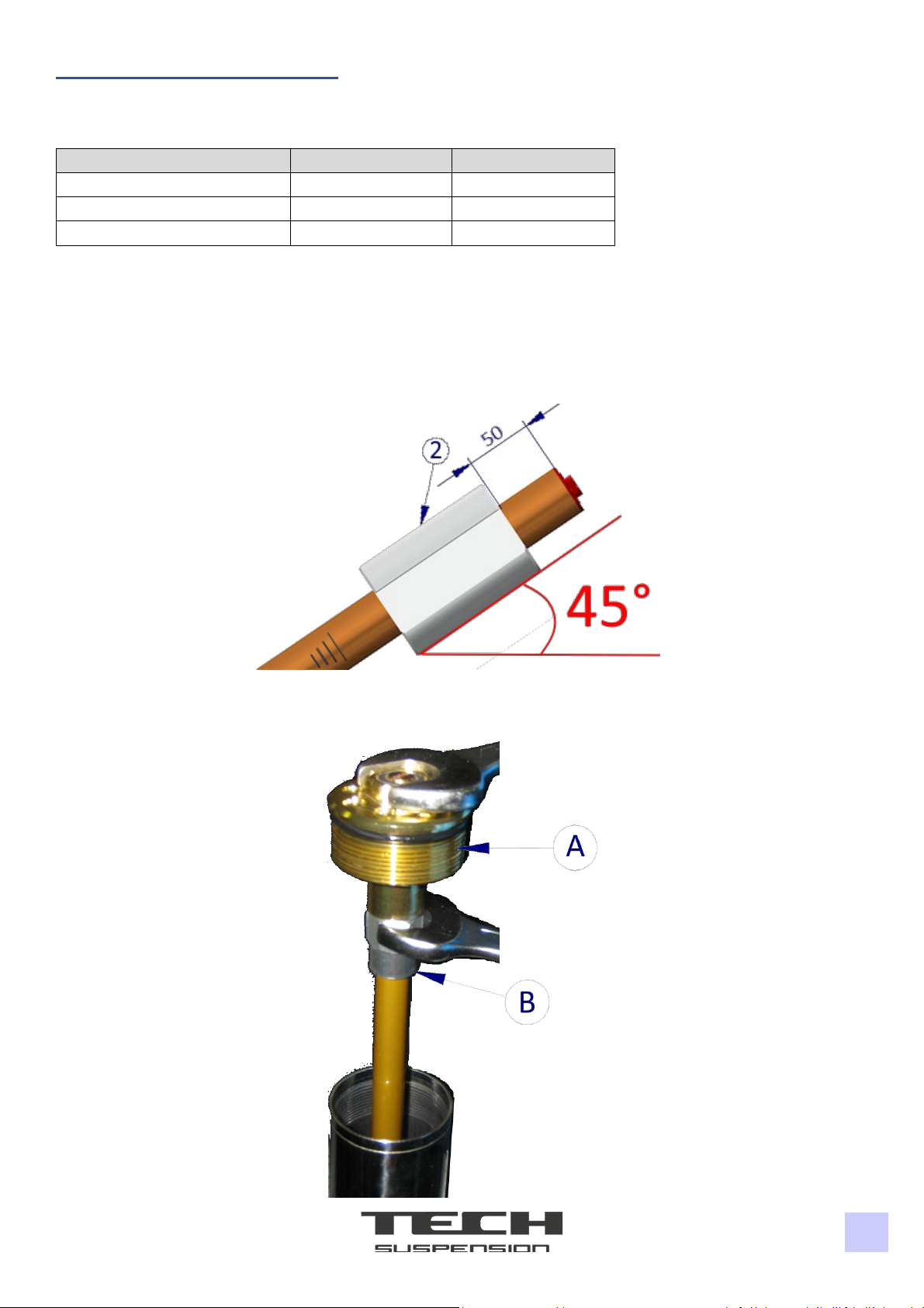
2. Tighten the tube on a bench vise with Tool 2 with an angle of 45°. Let the tube come out of the tool by 50 mm.
Keep the fork in this position until step N°6;
3. Unscrew the cap (A) with a 17 mm combined wrench and clean it;
4. Remove the conical spacer (B), the spacer (C) and the washer (D);
5. Slowly remove the spring (E) with a cloth. Clean properly the spring from oil residues;

10
6. Remove all oil from the fork and dispose of it according to local laws;
7. Put the fork in a vertical position and insert 250 mL of Oil OJ01 (SAE05). Move the tube up and down multiple
times, then push it to the end of the stroke;
8. Measure the oil level from the edge of the tube and adjust the level according to the sheet on page 4/5;

11
9. Insert the spring (E) inside the fork;
10. Insert in the same order components D, C, B;
11. Manually screw cap (A) on the tube. Tighten the tube on a bench vise with Tool 2 with an angle of 45°. Let the
tube come out of the tool by 50 mm and tighten the cap (A) with a 17 mm combined wrench and a tightening
torque of 10/12 Nm;
-End of Procedure-

12
Oil Change Right Leg
Tools:
Descrizione
Posizione
Part number
Stanchion Tube Tool
2
080004000
Combined wrench 14 mm, 17 mm, Hex key 1,5 mm, 12 mm
Procedure:
1. Before proceeding accurately clean the fork;
2. Tighten the tube on a bench vise with Tool 2 with an angle of 45°. Let the tube come out of the tool by 50 mm.
Keep the fork in this position until step N°6;
3. Unscrew the cap (A) with a 17 mm combined wrench and remove it from the tube. Insert a 14 mm combined
wrench on the locknut (B) and disassemble the two components. Remove the cap (A) and clean it;

13
4. Keep the cap (C) inside the cartridge stem. Remove all the oil inside the cartridge by moving up and down the
stem and dispose of it according to local laws;
5. Put the fork in a vertical position and insert 250 mL of Oil OJ01 (SAE05). Move the cartridge stem up and down
multiple times until the rebound has homogenous braking;
6. Measure the oil level from the edge of the tube and adjust the level according to the sheet on page 4/5;
14
7. Screw the locknut downwards (B). Manually screw the cap (A) on the stem;
8. Manually screw cap (A) on the tube. Tighten the tube on a bench vise with Tool 2 with an angle of 45°. Let the
tube come out of the tool by 50 mm. Screw the locknut (B) on the cap (A). Hold the locknut with a 14 mm
combined wrench and screw the cap (A) with a 17 mm combined wrench and a tightening torque of 10/12 Nm;
9. Tighten the cap (A) on the tube with a 17 mm combined wrench and a tightening torque of 10/12 Nm.
-End of Procedure-
15
Seals Replacement Left Leg
Tools:
Description
Position
Part number
Bushing and Oil Seal Tool
1
0800DU007
Stanchion Tube Tool
2
080004000
Cartridge Assembly Tool
3
080008000
Combined wrench 17 mm, Hex key 12 mm
Procedure:
1. Before proceeding accurately clean the fork;
2. Tighten the tube on a bench vise with Tool 2 with an angle of 45°. Let the tube come out of the tool by 50 mm.
Keep the fork in this position until step N°6;
3. Unscrew the cap (A) with a 17 mm combined wrench and clean it;
4. Remove the conical spacer (B), the spacer (C) and the washer (D);
5. Slowly remove the spring (E) with a cloth. Clean properly the spring from oil residues;

16
6. Remove all oil from the fork and dispose of it according to local laws;
7. Tighten the wheel’s axle in a bench wise with aluminium plates and insert the leg on the axle;
8. Push the tube inside the leg (end stroke) and insert Tool 3 inside the tube to disassemble the pumping stem (G),
then unscrew the regulator for the end stroke (F) with a 12 mm hexagonal key;
9. Extract the regulator and the copper washer (F). Remove the pumping stem (G);
10. Turn the fork upside down to remove the end stroke cone (H);
11. Remove the dust seal (I) by leveraging on its side with a flat-head screwdriver, then remove the seeger ring (J)
from its housing;
17
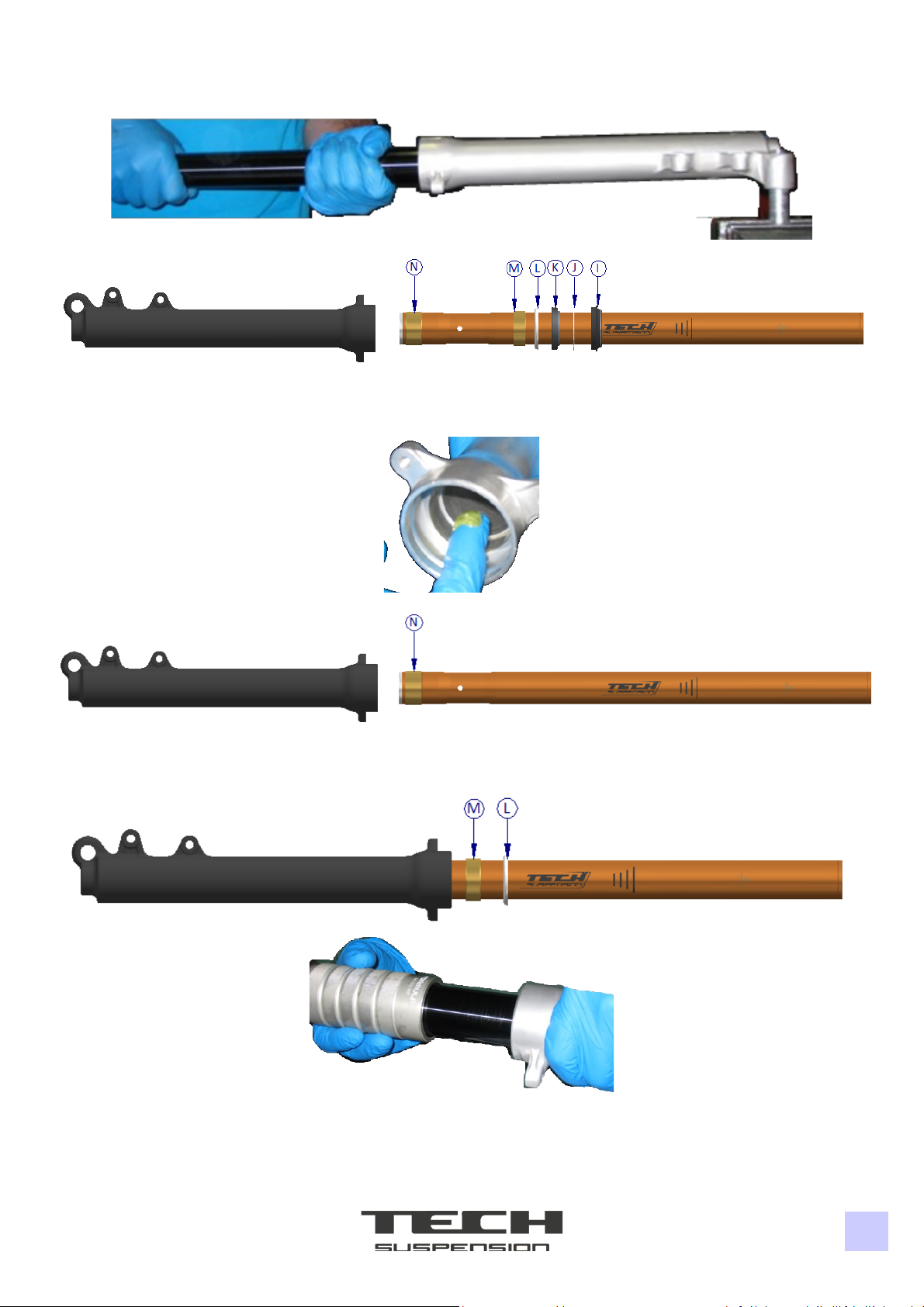
12. Tighten the wheel’s axle in a bench wise with aluminium plates and insert the leg on the axle. Forcefully pull the
tube out of the leg ad remove all parts from the tube (I-N);
13. Replace the bushing (N) with a new one. Apply grease on the bushing and oil seal housing;
14. Insert the tube with the new bushing (N) inside the leg;
15. Insert the upper bushing (M) and the oil seal support washer (L) on the tube. Push the parts inside with Tool 1
from the side without knurling;

18
16. Insert the oil seal (K) with Tool 1 from the side with the knurling. Manually insert the seeger ring (J) in its housing
making sure it’s properly assembled;
17. Apply grease in the highlighted area. Rotate the dust seal (J) on the grease and insert the dust seal in its housing
by pushing on its outer diameters with a screwdriver;
18. Insert the pumping stem (G) along with the end stroke cone (H) inside the tube;
19. Push the tube inside the leg (end stroke) and insert Tool 3 inside the tube to assemble the pumping stem (G).
Push Tool 3 against the pumping stem (G) and screw the regulator for the end stroke (F) with a 12 mm hexagonal
key and a tightening torque of 23,5/25,5 Nm;
20. Put the fork in a vertical position and insert 250 mL of Oil OJ01 (SAE05). Move the tube up and down multiple
times, then push it to the end of the stroke;

19
21. Measure the oil level from the edge of the tube and adjust the level according to the sheet on page 4/5;
22. Insert the spring (E) inside the fork;
23. Insert in the same order components D, C, B;
24. Manually screw cap (A) on the tube. Tighten the tube on a bench vise with Tool 2 with an angle of 45°. Let the
tube come out of the tool by 50 mm and tighten the cap (A) with a 17 mm combined wrench and a tightening
torque of 10/12 Nm;
-End of Procedure-
20
Seals Replacement Right Leg
Tools:
Description
Position
Part number
Bushing and Oil Seal Tool
1
0800DU007
Stanchion Tube Tool
2
080004000
Cartridge Assembly Tool
3
080008000
Combined wrench 14 mm, 17 mm, Hex key 1,5 mm, 12 mm
Procedure:
1. Before proceeding accurately clean the fork;
2. Tighten the tube on a bench vise with Tool 2 with an angle of 45°. Let the tube come out of the tool by 50 mm.
Keep the fork in this position until step N°6;
3. Unscrew the cap (A) with a 17 mm combined wrench and remove it from the tube. Insert a 14 mm combined
wrench on the locknut (B) and disassemble the two components. Remove the cap (A) and clean it;
Table of contents
Other Formula Bicycle Accessories manuals

Formula
Formula MD1 Manual

Formula
Formula MOD User manual

Formula
Formula FD40292-20 User manual

Formula
Formula TECH SUSPENSION TJ2 User manual

Formula
Formula NERO R User manual

Formula
Formula Linea User manual

Formula
Formula THIRTYFIVE QR15 User manual

Formula
Formula 4 Racing User manual

Formula
Formula R1 Racing User manual
Popular Bicycle Accessories manuals by other brands


Cycling Sports Group
Cycling Sports Group DT-3267 instruction manual

Miche
Miche EVO MAX BB30 Mount instructions

Bobike
Bobike Go Maxi Carrier Assembly instructions

Grin Technologies
Grin Technologies Phaserunner V3 quick start guide

Asaklitt
Asaklitt JY-7129-200 Instructions for use

SP CONNECT
SP CONNECT STEM MOUNT Mounting instructions


