manuals.online logo
Brands
  1. Home
  2. •
  3. Brands
  4. •
  5. Fortin
  6. •
  7. Automobile Accessories
  8. •
  9. Fortin EVO-CAN User manual

Fortin EVO-CAN User manual

Rev.20110208
Page 1 / 5
ADDENDUM - SUGGESTED WIRING CONFIGURATION
SCHÉMA DE BRANCHEMENT SUGGÉRÉ
GX460
2010-2011
Parts required
1x 5A Fuse Pièces requises
1x Fusible 5A
PUSH
START
GX460
LEXUS
Smart-Key
Co
F
Fo
r
IMI White
IMO LightBlue
C
Copyright © 2010,
Fortin Auto Radio Inc
+
12V Battery Black
C
Copyright © 2010,
Fortin Auto Radio Inc
(+) Start Black
(+) Ignition2 Blue
(+) Accessory Red
OBDII
At Parking Light harness
Au harnais des lumières de
stationnement
(-) Parking Lights Red
C
Copyright © 2010,
Fortin Auto Radio Inc
C
Copyright © 2010,
Fortin Auto Radio Inc
C
Copyright © 2010,
Fortin Auto Radio Inc
Behind Glove box
Derrière le coffre à gant
EVO-CAN firmware version :
2.12 and more | et plus
GX460_ PUSH TO START CONTINUED | SUITE
3 PIN
CO
NN
.
Hood Pin: Only if equipped.
Pin Capot: Seulement si équipé.
N.C.
EVO-C
A
N
Dk. Blue
Orange/Black
Purple/White
Purple
Unlock/Disarm
Lock/Arm
Ground While Running
Green
White Trunk Status
Door Status
Brown/White
Pink
Hand Brake Status
Tachometer
Foot Brake Status
10
N.C.
N.C.
Yellow/Black Trunk Release
Lt. Blue/Black
Pink/Black Hood Status
Lt. Blue
N.C.
31
32
33
34
35
36
25
26
27
28
29
30
21
22
23
24
4
5
6
1
2
3
10
11
12
7
8
9
16
17
18
15
19
20
13
14
Light Blue
Bleu Pâle
White
Blanc
ECM
Behind glove box
Derrière le coffre à gant
Back view -
Vue de dos -
IMO
IMI
6 PIN RED
CO
NN
.
White/Green
White/Red
N.C.
N.C.
N.C.
N.C.
CAN High (Pin 6)
IMI
IMO
CAN High (Pin 6)
Gray
Gray/Black
CAN 2 HIGH
CAN 2 LOW 6
14
CAN Low (Pin 14)
OBDII
Front view
Vue de face
N.C.
4 Pin
Cut off one plug of the 4 Pin
Data-Link connector
Connect the Red wire to +12V
Connect the Black wire to
Ground
1
2
3
Coupez l'extrémité du connecteur
4 pins Data-Link
Connectez le fil rouge au 12V
Connectez le fil noir à la masse
du véhicule.
1
2
3
Remote
Starter/Alarm
Démarreur à
distance/alarme
Connect to vehicle
Branchement au véhicule
Connect to Remote-Starter/Alarm
Branchement au démarreur à
distance/Alarme
Input
Entrée
Output
Sortie Connection not required with Data-link
Branchement non requis avec Data-Link
Connection always required
Branchement toujours requis
INSTALLATION WITHOUT DATA-LINK
INSTALLATION SANS DATA-LINK
INSTALLATION WITH DATA-LINK
INSTALLATION AVEC DATA-LINK
Remote
Starter/Alarm with
the Fortin Data-link
protocol.
Démarreur à
distance/alarme
avec le protocole
Data-link Fortin
Red | Rouge +12V
Black | Noir Ground
4 Pin
}
2This manual may change without notice. www.ifar.ca for latest version.
Page 2 / 5
10A MAX
Replace the Remote-Starter
fuse with a 5A to 10A (MAX)
Changez la fusible du
démarreur a distance par une
fusible 5A to 10A (MAX)
Red
Rouge
1
11
www.fortinbypass.com WEB UPDATE | MISE À JOUR INTERNET
Blue
Bleu
12V Battery
12V Batterie
Ignition 2
Start
Accessory
Accessoire
Ignition 1
GX460 CONTINUED | SUITE_ PUSH TO START
Back view -
Behind Glove box
Vue de dos -
Derrière le coffre
à gant
Black connector
Connecteur Noir
Back view -
Behind Glove box
Vue de dos -
Derrière le coffre
à gant
White connector
Back view -
Behind Glove box
Vue de dos -
Derrière le coffre
à gant
REMOTE STARTER
DÉMARREUR À
DISTANCE
Black
Noir
Violet
Black
Noir
Red
Rouge
Parking Lights
Feux de
stationnement
Back view -
Vue de dos -
Parking light switch
Commutateur de feux
de stationnement
3
Ce Guide peut faire l’objet de changement sans préavis. www.ifar.ca pour la récente version. Page 3 / 5
Lorsque le DEL Bleu clignote
rapidement, appuyez une fois sur le
bouton démarrage (Push-to-Start) pour
éteindre l'ignition.
Le DEL Bleu s'éteint pour indiquer que le
module est programmé.
ENGINE
START
STOP
ENGINE
START
STOP
x1
x1
ON
OFF
Once the Blue LED starts to flash rapidly
press the once to
shut off the ignition.
The Blue LED will turn off to indicate the
module has been programmed.
Push-to-Start button
5
6
ENGINE
START
STOP
x1 ON
Démarrez à distance.
Entrez dans le véhicule avec la clé
intelligente (Intelli-Key),
appuyez 2 fois sur le bouton
démarrage (Push-to-Start) du véhicule.
Vous êtes maintenant prêt à embrayer
et prendre la route.
Remote start the vehicle.
Enter the vehicle with the Intelli-Key
and
press the Push to Start button twice.
The vehicle can now be put in to gear
and driven.
ENGINE
START
STOP
x1 OFF
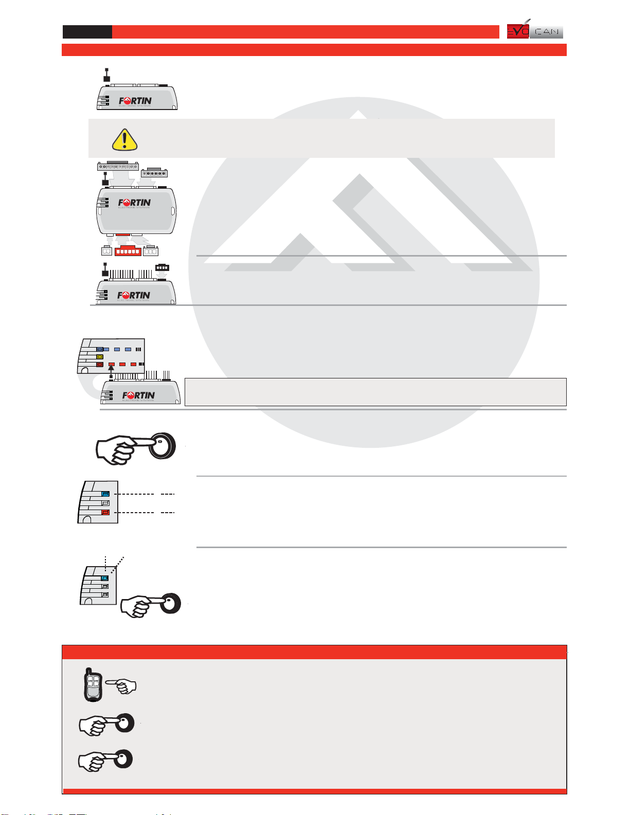
PROGRAMMING PROCEDURE | PROCÉDURE DE PROGRAMMATION
Press on the brake pedal and
Press the Push-to-Start button once to
start the engine.
Appuyer sur la pédale de frein et
Appuyez 1 fois sur le bouton
démarrage (Push-to-Start) pour
démarrer le moteur
REMOTE STARTER FUNCTIONNALITY | FONCTIONNALITÉS DU DÉMARREUR À DISTANCE
Les DELS alternent entre un flash
BLEU et ROUGE,
Relâchez le bouton de programmation
quand la DEL est ROUGE.
The LED will alternate between
BLUE and RED flashes.
Release the programming button when
the LED is RED.
If the LED is not solid RED disconnect the 4 Pin
connector (Data-Link) and go back to step 3
Press and hold the programming
button:
Pressez le bouton de programmation:
2
4
1
Si le DEL n'est pas ROUGE débranchez le
connecteur 4 pins (Data-Link) et allez à l'étape 3
Still holding the programming button,
Insert the 4 Pin (Data-Link) connector
into the EVO-CAN module.
En gardant le bouton de programmation
enfoncé,
Insérez le connecteur 4 pins (Data-Link)
dans le EVO-CAN.
3
Insert the connectors in the
following order:
Insérez les connecteurs dans
l'ordre suivant:
The Red LED will flash 10 times,
Key bypass : programming complete.
For all other functions: wait for the Blue
light to flash.
La DEL Rouge clignote 10 fois :
Contourtement de clé: programmation
complèté.
attendre que la
DEL Bleu clignote.
Pour tous autre options:
Flash
10 times
1
LED | DEL
EVO-CAN
Insert the remaining connectors:
- 6 pin connector (White)
- 3 pin connector (White)
- 6 pin connector (Red)
- 2 pin connector (White)
* If required.
- 10 pin connector (White)
Insérez les connecteurs restants:
- connecteur 10 pins (Blanc).
- connecteur 3 pins (Blanc).
- connecteur 6 pins (Rouge).
- connecteur 2 pins (Blanc).
- connecteur 6 pins (Blanc).
* Si requis.
4This manual may change without notice. www.ifar.ca for latest version.
Page 4 / 5
TECH SUPPORT
Tél: 514-255-HELP (4357)
1-877-336-7797
ADDENDUM GUIDE WEB UPDATE | MISE À JOUR INTERNET
www.fortinbypass.com
WARNING / TECH SUPPORT / MISE EN GARDE / SUPPORT TECHNIQUE
L'information de ce guide est fournie sur la base de représentation (telle quelle) sans aucune garantie de précision et
d'exactitude. Il est de la seule responsabilité de l'installateur de vérifier tous les fils et circuit avant défectuer les
connections. Seule une sonde logique ou un multimètre digital doivent être utilisés.
n'assume aucune responsabilité de l'exactitude de l'information fournie. L'installation (dans chaque
cas) est la responsabilité de l'installateur effectuant le travail. FORTIN SYSTÈMES ÉLECTRONIQUES n'assume aucune
responsabilité suite à l'installation, que celle-ci soit bonne ou mauvaise ou de n'importe autre type. Ni le manufacturier, ni le
distributeur ne se considèrent responsables des dommages causés ou ayant pu être causés, indirectement ou
directement, par ce module, excepté le remplacement de ce module en cas de défectuosité de fabrication. Ce module doit
être installé par un technicien qualifié. L'information fournie dans ce guide est une suggestion. Ce guide d'instruction peut
faire l’objet de changement sans préavis. Consultez le pour voir la plus récente version.
FORTIN SYSTÈMES
ÉLECTRONIQUES
www.fortinbypass.com
The information on this sheet is provided on an (as is) basis with no representation or warranty of accuracy whatsoever. It is
the sole responsibility of the installer to check and verify any circuit before connecting to it. Only a computer safe logic probe
or digital multimeter should be used. FORTIN ELECTRONIC SYSTEMS assumes absolutely no liability or responsibility
whatsoever pertaining to the accuracy or currency of the information supplied. The installation in every case is the sole
responsibility of the installer performing the work and FORTIN ELECTRONIC SYSTEMS assumes no liability or
responsibility whatsoever resulting from any type of installation, whether performed properly, improperly or any other way.
Neither the manufacturer or distributor of this module is responsible of damages of any kind indirectly or directly caused by
this module, except for the replacement of this module in case of manufacturing defects. This module must be installed by
qualified technician. The information supplied is a guide only. This instruction guide may change without notice. Visit
www.fortinbypass.com to get the latest version.
EVO-CAN
Copyright © 2006-2011, FORTIN AUTO RADIO INC ALL RIGHTS RESERVED PATENT PENDING
Service No : 000 102 04 2536
Date: xx-xx
INTERFACE MODULE
Made in Canada
PATENTS PENDING US: 2007-228827-A1
www.fortinbypass.com
HARDWARE VERSION
FIRMWARE VERSION
Module label | Étiquette sur le module
Updated firmware and installation guides are posted on our web
site on a regular basis. We recommend that you update this module to
the latest firmware and download the latest installation guide(s) prior
to the installation of this product.
Des mises à jour du Firmware (microprogramme) et des
guides d'installation sont mises en ligne régulièrement. Vérifiez
que vous avez bien la dernière version logiciel et le dernier guide
d'installation avant l'installation de ce produit.
EVO-CAN
Notice: Installation GuidesUpdated Firmware and

Other manuals for EVO-CAN

7

Other Fortin Automobile Accessories manuals

Fortin KEY-OVERRIDE-ALL User manual

Fortin

Fortin KEY-OVERRIDE-ALL User manual

Fortin Evo All THAR-CHR4 User manual

Fortin

Fortin Evo All THAR-CHR4 User manual

Fortin EVO ONE THAR-ONE-HON6 User manual

Fortin

Fortin EVO ONE THAR-ONE-HON6 User manual

Fortin EVO ONE User manual

Fortin

Fortin EVO ONE User manual

Fortin EVO ONE User manual

Fortin

Fortin EVO ONE User manual

Fortin EVO ONE User manual

Fortin

Fortin EVO ONE User manual

Fortin TB-TOYOTA User manual

Fortin

Fortin TB-TOYOTA User manual

Fortin EVO ONE User manual

Fortin

Fortin EVO ONE User manual

Fortin EVO KEY User manual

Fortin

Fortin EVO KEY User manual

Fortin Evo All THAR-FOR3 User manual

Fortin

Fortin Evo All THAR-FOR3 User manual

Fortin EVO ALL User manual

Fortin

Fortin EVO ALL User manual

Fortin EVO-ONE User manual

Fortin

Fortin EVO-ONE User manual

Fortin EVO KEY User manual

Fortin

Fortin EVO KEY User manual

Fortin EVO ALL Installation and operating instructions

Fortin

Fortin EVO ALL Installation and operating instructions

Fortin INT-SL User manual

Fortin

Fortin INT-SL User manual

Fortin EVO ONE THAR-GM7 User manual

Fortin

Fortin EVO ONE THAR-GM7 User manual

Fortin EVO-ALL User manual

Fortin

Fortin EVO-ALL User manual

Fortin EVO-ALL User manual

Fortin

Fortin EVO-ALL User manual

Fortin EVO ONE Installation and operating instructions

Fortin

Fortin EVO ONE Installation and operating instructions

Fortin EVO ONE User manual

Fortin

Fortin EVO ONE User manual

Fortin EVO-KEY User manual

Fortin

Fortin EVO-KEY User manual

Fortin EVO KEY User manual

Fortin

Fortin EVO KEY User manual

Fortin Evo One THAR-ONE-HON4 User manual

Fortin

Fortin Evo One THAR-ONE-HON4 User manual

Fortin EVO ALL User manual

Fortin

Fortin EVO ALL User manual

Popular Automobile Accessories manuals by other brands

Magneti Marelli AC161 Installation instruction

Magneti Marelli

Magneti Marelli AC161 Installation instruction

FDI uEZ GUI Start here

FDI

FDI uEZ GUI Start here

JCROffroad JT Install instructions

JCROffroad

JCROffroad JT Install instructions

Rostra VOXXElectronics 250-1930 owner's guide

Rostra

Rostra VOXXElectronics 250-1930 owner's guide

TOP VEHICLE TECH GR3FORD5 installation manual

TOP VEHICLE TECH

TOP VEHICLE TECH GR3FORD5 installation manual

Safe Fleet PRIME DESIGN AR-2000-BLK manual

Safe Fleet

Safe Fleet PRIME DESIGN AR-2000-BLK manual

Skoda Fabia Combi 5J Fitting instructions

Skoda

Skoda Fabia Combi 5J Fitting instructions

Camcar 40077 Al Mounting instructions

Camcar

Camcar 40077 Al Mounting instructions

Camcar 40089 AL Mounting instructions

Camcar

Camcar 40089 AL Mounting instructions

Impac Tradesman 2000 installation manual

Impac

Impac Tradesman 2000 installation manual

DVB OFFROAD BRSB-01 installation manual

DVB

DVB OFFROAD BRSB-01 installation manual

Safari Snorkel SS385HF installation guide

Safari Snorkel

Safari Snorkel SS385HF installation guide

ULTIMATE SPEED 279746 Assembly and Safety Advice

ULTIMATE SPEED

ULTIMATE SPEED 279746 Assembly and Safety Advice

SSV Works DF-F65 manual

SSV Works

SSV Works DF-F65 manual

ULTIMATE SPEED CARBON Assembly and Safety Advice

ULTIMATE SPEED

ULTIMATE SPEED CARBON Assembly and Safety Advice

Witter F174 Fitting instructions

Witter

Witter F174 Fitting instructions

WeatherTech No-Drill installation instructions

WeatherTech

WeatherTech No-Drill installation instructions

TAUBENREUTHER 1-336050 Installation instruction

TAUBENREUTHER

TAUBENREUTHER 1-336050 Installation instruction

manuals.online logo
manuals.online logoBrands
  • About & Mission
  • Contact us
  • Privacy Policy
  • Terms and Conditions

Copyright 2025 Manuals.Online. All Rights Reserved.