manuals.online logo
Brands
  1. Home
  2. •
  3. Brands
  4. •
  5. Frico
  6. •
  7. Heater
  8. •
  9. Frico PAECS User manual

Frico PAECS User manual

PAECS
Original instructions
... 9
SE .... 12
GB .... 14
NO .... 17
DE .... 21
ES .... 25
FR
.... 29
IT .... 33
NL .... 37
FI .... 40
PL .... 44
RU
Introduktionssidorna består huvudsakligen av bilder. För översättning av de
engelska texter som används, se respektive språksidor.
SE
The introduction pages consist mainly of pictures. For translation of the
English texts used, see the respective language pages.
GB
Introduksjonssidene består hovedsakelig av bilder. For oversettelse av de
engelske tekstene, se de respektive språksidene
NO
Les pages de présentation contiennent principalement des images. Pour la
traduction des textes en anglais, consultez la page correspondante à la langue
souhaitée.
FR
Die Einleitungsseiten bestehen hauptsächlich aus Bildern. Für die Übersetzung
der verwendetenTexte in englischer Sprache, siehe die entsprechenden
Sprachseiten.
DE
Las páginas introductorias contienen básicamente imágenes. Consulte la
traducción de los textos en inglés que las acompañan en las páginas del
idioma correspondiente.
ES
De inleidende pagina's bevatten hoofdzakelijk afbeeldingen.Voor een vertaling
van de gebruikte Engelse teksten, zie de pagina's van de resp. taal.
NL
Le pagine introduttive contengono prevalentemente immagini. Per le
traduzioni dei testi scritti in inglese, vedere le pagine nelle diverse lingue.
IT
Początkowe strony zawierają głównie rysunki. Tłumaczenie wykorzystanych
tekstów angielskich znajduje się na odpowiednich stronach językowych.
PL
RU Страницы в начале Инструкции состоят в основном из рисунков, схем и
таблиц. Перевод встречающегося там текста приведен в разделе RU.
PAECS
3
Fig. 1
min 500
min 500 min 500
11 7
18
209
10 245
90,5
157
1571,8 m
1,5 m
11 7
157
18
1012/1522/2012
1050/1560/2050
1; 1,5
m
2 m
1,5 m
1,8 m
PAECS
4
Fig. 2: Stepless airflow control. Internal potentiometer for low and high speed (accessible through the
outlet grille).
5
010
5
010
Fig.3: Open the unit.
AB
C
TX20
Potentiometer,
high speed, 6V
Potentiometer,
low speed, 2.5V
PAECS
5
min 500 mm
Fig. 4: Mounting with wall brackets
Mounting with wall brackets
AB
C
PAECS10 2 pcs
PAECS15 2 pcs
PAECS20 3 pcs
D
203575
210
33
ø8 (3x)
ø5
ø10
162
PAECS
6
SIReDC
Accessories
PA34TR PA2P PA2PF
PA34TR15 PAECS10, PAECS15, 1 m
PA34TR20 PAECS20, 1 m
PA2P15 PAECS10, PAECS15, 1 m
PA2P20 PAECS20, 1 m
PA2PF15 PAECS10, PAECS15
PA2PF20 PAECS20
AGB304
SIReDC
AGB304
PAECS
7
Stepless airflow control with door contact / position limit switch
PAECS
PENL
~
M~
M
PENL
PE
PE
N
N
L
L
6
6
5
5
4
4
3
3
2
2
1
1
A
A
Yellow
Blue
Red
White
White
Red
Yellow
Blue
White
Red
Yellow
Blue
Only2mversion
Yellow/0-10VPWM
Red/+10V
White/ Tach
Blue / GND
Right motor
Left motor
No Nc
SIReDC
10 0
White
Com
Green
Green
Brown
Brown
White
PAECS10/15/20
10 0
DiodePAECS10
Wire PAECS15
WirePAECS20
PAECS
8
Type Output
[kW]
Airflow
[m3/h]
Sound
power*1
[dB(A)]
Sound
pressure*2
[dB(A)]
Voltage
motor
[V]
Amperage
motor*3
[A]
Length
[mm]
Weight
[kg]
PAECS10 0 1450*477 44/62 230V~ 0,14/0,79 1050 15
PAECS15 0 2200*478 45/62 230V~ 0,20/1,17 1560 20
PAECS20 03100*483 51/67 230V~ 0,50/2,12 2050 30
1Ambient, no heat - PAECS
*1) Sound power (LWA) measurements according to ISO 27327-2: 2014, Installation type E.
*2) Sound pressure (LpA). Conditions: Distance to the unit 5 metres. Directional factor: 2. Equivalent
absorption area: 200 m². At 50% and 100% airflow.
*3) Applicable at 50% and 100% airflow.
*4) Max. airflow, 10V.
Protection class: IP44.
CE compliant.
PAECS
12
GB
General Instructions
Read these instructions carefully before
installation and use. Keep this manual for
future reference.
The product may only be used as set out in
the assembly and operating instructions. The
guarantee is only valid if the product is used
in the manner intended and in accordance
with the instructions.
Application
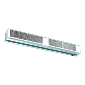
PAECS is an air curtain for cold storage
and freezer rooms as well as entrances.
Installation height is up to 4 metres (cold
storage) and up to 2,5 metres (entrances).
The air curtain is prepared for stepless
control.
Protection class: IP44.
Operation
Air is drawn in at the top of the unit and
blown out downwards so that it shields the
door opening and minimizes heat loss. To
achieve the optimum curtain effect the
unit must extend the full width of the door
opening.
The grille for directing exhaust air is
adjustable and is normally angled outwards to
achieve the best protection against incoming
air.
The efficiency of the air curtain depends
on the air temperature, pressure differences
across the doorway and any wind pressure.
NOTE! Negative pressure in the building
considerably reduces the efficiency of the air
curtain. The ventilation should therefore be
balanced.
Installation and operating instructions
Mounting
The air curtain unit is installed horizontally
with the supply air grille facing downwards as
close to the door as possible. When the unit is
used to protect cold storage or freezer rooms,
it must be mounted on the outside of the
conditioned space.
Brackets and torx bit are enclosed in the
gable end packaging upon delivery.
Mounting with wall brackets (fig. 4)
1.Mount the brackets on the wall, see fig.4A
and dimension drawing fig.1. If the wall is
uneven the brackets must be compensated
for this.
2.Hook on the unit at the lower edge of the
brackets. (Fig.4B)
3.Bend the top of the console over the the
unit and slide the units screws along the
rail into the slots on the consoles. (Fig.4C)
When the bracket is bent once, it must be
replaced if bent back more than 45 °.
4.Lock the nuts against the brackets. (Fig.4D)
Horizontal mounting on the ceiling
Threaded rods, hanging brackets and ceiling
mounting brackets for ceiling mounting are
available as accessories, see accessories pages
and separate manuals.
Control options
Stepless airflow control with door contact/posi-
tion limit switch
When the door is closed the fan runs at low
speed, set on the internal potentiometer
0-10V, which is located inside the outlet
grille. When the door opens, the fan runs
at high speed, set on the second internal
potentiometer. This control option gives low
response time and the best protection.
BMS control
The air curtain can also be controlled via BMS
(0-10V).
See Figure 2 and Accessories pages.
Connection
The unit is connected with a 1.5m cord and
plug. Prepared with extracted control wiring
so that external control can be connected
easily. NB! A door contact must be connected
before connecting the unit to the power
supply.
Adjustment of the air curtain and air flow
The direction and speed of the air flow should
be adjusted considering the load on the
opening. Pressure forces affect the air stream
and make it bend inwards into the premises
(when the premises are heated and the
outdoor air is cold).
The air stream should therefore be directed
PAECS
13
GB
Overheating
The motors have built-in protection against
overheating and will automatically regulate
their speed at high temperatures.
Replacing motor or impeller
1.Remove the front.
2.Remove gable end.
3.Remove the screw between motor and fan.
4.Disconnect the cables to the motor.
5.Remove the screws securing the motor and
lift it out together with the impeller.
Basic setting fan speed
The fan speed for open respectively closed
door is pre-set on the internal potentiometers
(6V open/high speed, 2,5V closed/low speed).
Note that the air flow direction and fan speed
may need fine adjustment depending on the
loading of the door.
Service, repairs and maintenance
For all service, repair and maintenance first
carry out the following:
1.Disconnect the power supply.
2.The front hatch is removed by removing
the screws on the top of the unit and then
detach the bent edge at the bottom. (Fig.3)
3.After the service, repair and maintenance
reattach the front hatch. Place the hatch
at the lower edge with the bent edge and
fasten on top with screws.
Note that when carrying out work where the
end is removed, the outlet grille also detaches.
Maintenance
Since fan motors and other components are
maintenance free, no maintenance other than
cleaning is necessary. The level of cleaning
can vary depending on local conditions.
Undertake cleaning at least twice a year. Inlet
and exhaust grilles, impeller and elements
can be vacuum cleaned or wiped using a
damp cloth. Use a brush when vacuuming
to prevent damaging sensitive parts. Avoid
the use of strong alkaline or acidic cleaning
agents.
6.Install the new motor and/or the new
impeller as above in reverse order.
Trouble shooting
If the fans are not working or do not blow pro-
perly, check the following:
• The functions and settings of the built-in
control system.
• That the intake grille/filter is not dirty.
If the fault cannot be rectified, please contact
a qualified service technician.
Safety
• Keep the areas around the air intake
and exhaust grilles free from possible
obstructions!
• Lifting equipment must be used to lift the
unit.
• This appliance can be used by children
aged from 8 years and above and persons
with reduced physical, sensory or
mental capabilities or lack of experience
and knowledge if they have been given
supervision or instruction concerning
use of the appliance in a safe way and
understand the hazards involved. Children
shall not play with the appliance. Cleaning
and user maintenance shall not be made
by children without supervision.
• Children of less than 3 years should be
kept away unless continuously supervised.
• Children aged from 3 years and less than 8
years shall only switch on/off the appliance
provided that it has been placed or
installed in its intended normal operating
position and they have been given
supervision or instruction concerning
use of the appliance in a safe way and
understand the hazards involved.
• Children aged from 3 years and less
than 8 years shall not plug in, regulate
and clean the appliance or perform user
maintenance.
CAUTION — Some parts of this product can
become very hot and cause burns. Particular
attention has to be given where children and
vulnerable people are present.
outwards to withstand the load. Generally
speaking, the higher the load, the greater the
angle that is needed.
Main office
Frico AB Tel: +46 31 336 86 00
Industrivägen 41
SE-433 61 Sävedalen [email protected]
Sweden www.frico.net
For latest updated information and information
about your local contact: www.frico.se
Art.no 154845, 20181219 HH

This manual suits for next models

4

Other Frico Heater manuals

Frico Tiger P51 User manual

Frico

Frico Tiger P51 User manual

Frico Infracalm INC05E User manual

Frico

Frico Infracalm INC05E User manual

Frico Thermozone AD 400 W Series User manual

Frico

Frico Thermozone AD 400 W Series User manual

Frico SFS Series User manual

Frico

Frico SFS Series User manual

Frico Thermozone AC 400 User manual

Frico

Frico Thermozone AC 400 User manual

Frico AGS5500 User manual

Frico

Frico AGS5500 User manual

Frico IRCF User manual

Frico

Frico IRCF User manual

Frico SWS02 User manual

Frico

Frico SWS02 User manual

Frico Thermowarm TWT100 User manual

Frico

Frico Thermowarm TWT100 User manual

Frico Thermozone ACC10 User manual

Frico

Frico Thermozone ACC10 User manual

Frico CIR105 User manual

Frico

Frico CIR105 User manual

Frico PA3210CA User manual

Frico

Frico PA3210CA User manual

Frico Tiger P203 User manual

Frico

Frico Tiger P203 User manual

Frico Thermozone WAC 300 Series User manual

Frico

Frico Thermozone WAC 300 Series User manual

Frico 125-12B User manual

Frico

Frico 125-12B User manual

Frico IRC15 Service manual

Frico

Frico IRC15 Service manual

Frico IR3000 User manual

Frico

Frico IR3000 User manual

Frico SWX C Series User manual

Frico

Frico SWX C Series User manual

Frico SWX CE Series User manual

Frico

Frico SWX CE Series User manual

Frico Infrasmart IHS15W67 User manual

Frico

Frico Infrasmart IHS15W67 User manual

Frico ICW Series Parts list manual

Frico

Frico ICW Series Parts list manual

Frico Panther SE06N User manual

Frico

Frico Panther SE06N User manual

Frico Thermozone ADR300W Series User manual

Frico

Frico Thermozone ADR300W Series User manual

Frico Thermozone AD Corinte A - ADCS User manual

Frico

Frico Thermozone AD Corinte A - ADCS User manual

Popular Heater manuals by other brands

Black & Decker BXSH44004GB manual

Black & Decker

Black & Decker BXSH44004GB manual

Quest Engineering EHS 20 Pro Installation, operation and maintenance instructions

Quest Engineering

Quest Engineering EHS 20 Pro Installation, operation and maintenance instructions

Honeywell HCE200XE Series operating instructions

Honeywell

Honeywell HCE200XE Series operating instructions

HOMCOM 820-271 Assembly instruction

HOMCOM

HOMCOM 820-271 Assembly instruction

Princess 01.348700.02.001 instruction manual

Princess

Princess 01.348700.02.001 instruction manual

Campo Equipment BLAZE 9E product manual

Campo Equipment

Campo Equipment BLAZE 9E product manual

Soleus Air HGW-308 user manual

Soleus Air

Soleus Air HGW-308 user manual

RADtec T15YS instruction manual

RADtec

RADtec T15YS instruction manual

Qlima PEW 3020 operating manual

Qlima

Qlima PEW 3020 operating manual

Qlima ACH-312 PTC Important Instruction/User Manual

Qlima

Qlima ACH-312 PTC Important Instruction/User Manual

Sunbeam SCH4062 owner's guide

Sunbeam

Sunbeam SCH4062 owner's guide

DCG PTC180 instruction manual

DCG

DCG PTC180 instruction manual

enertik SWSP-200 Installation and operation manual

enertik

enertik SWSP-200 Installation and operation manual

Klarstein SKYSCRAPER HEAT manual

Klarstein

Klarstein SKYSCRAPER HEAT manual

comfortel 5350 owner's manual

comfortel

comfortel 5350 owner's manual

Trotec IDX 20 D Original instructions

Trotec

Trotec IDX 20 D Original instructions

Hearth Trends Oxford Infared Heater user manual

Hearth Trends

Hearth Trends Oxford Infared Heater user manual

dellonda DG177 instructions

dellonda

dellonda DG177 instructions

manuals.online logo
manuals.online logoBrands
  • About & Mission
  • Contact us
  • Privacy Policy
  • Terms and Conditions

Copyright 2025 Manuals.Online. All Rights Reserved.