Step 7 : To uninstall the lifeline, push the lock backwards in order to pull back the hockey. Hockey will release the pulley and
allow rope to loosen. Fig. 9
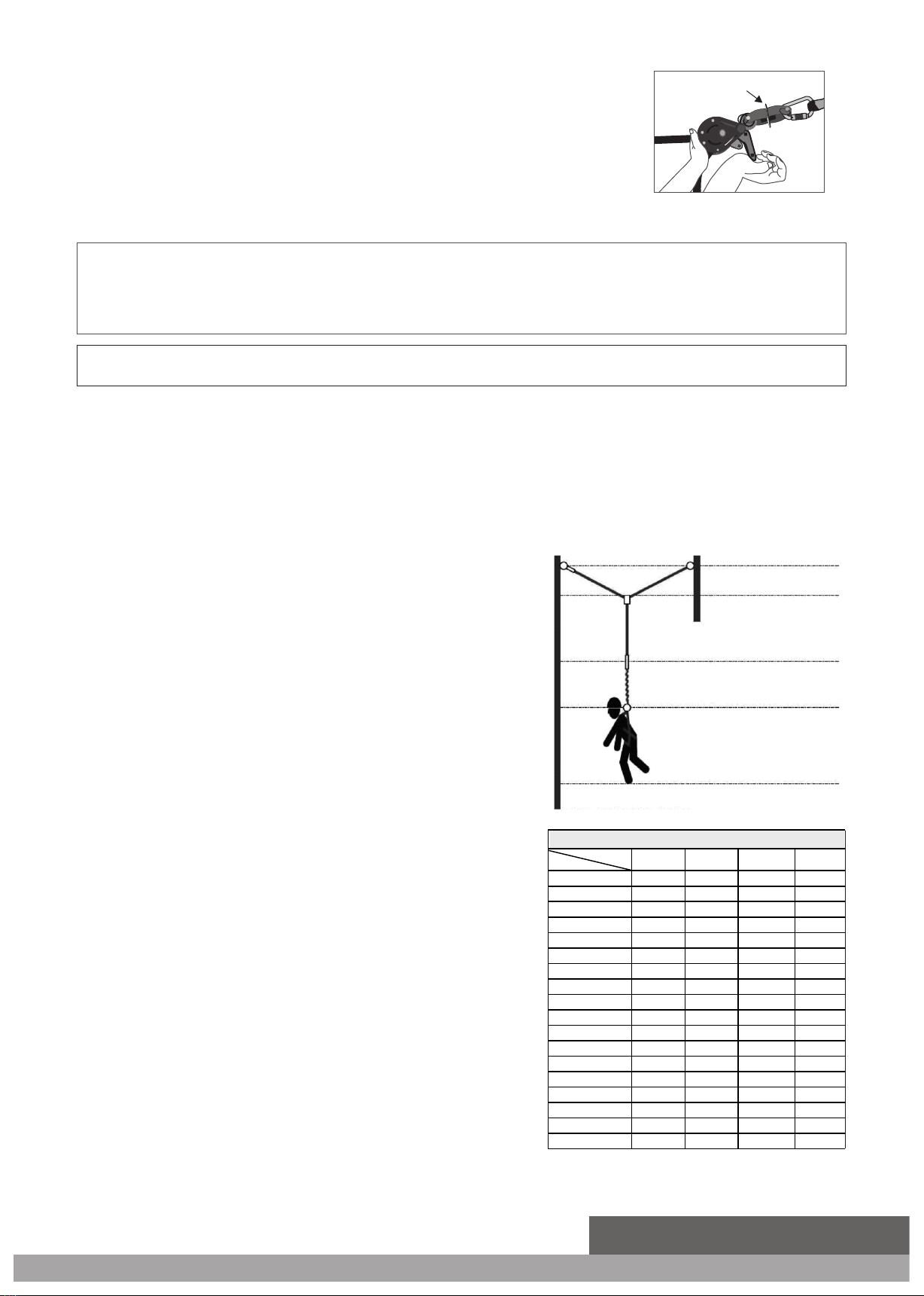
indicator by attaching a Carabiner to the hokey eye of tension indicator. Fig. 06
Ø Fall protection systems must be designed in a manner compliant with all federal, state, and safety regulations.
Ø Training of Authorized Persons to correctly erect, disassemble, inspect, maintain, store, and use
equipment must be provided by a Competent Person.
Ø NEVER use fall protection equipment of any kind to hang, lift, support, or hoist tools or equipment,
unless explicitly certified for such use.
Step 5 : Pull the initial slack of rope by hand and ensure that rope is seated properly in the groove of pulley. Fig. 07
Step 6 : Use an open end spanner of 0.944 inches provided along with tensioner to give appropriate tension to the lifeline. Plate
of Tension indicator will start to rotate freely once the required tension has been achieved in lifeline. Now, O rings/
pass through carriages can be used as mobile anchors for the workers. Fig. 08
Step 9 : After uninstallation, inspect the entire lifeline for any evidence of damage, wear, corrosion on tensioner body and
separation of rope fibers.
Do not alter& misuse the equipment.
NOTE:-
Ø Workplace conditions, including, but not limited to, flame, corrosive chemicals, electrical shock, sharp objects, machinery, abrasive substances, weather conditions, and
uneven surfaces, must be assessed by a Competent Person before fall protection equipment is selected.
Ø Fall protection systems must be selected and installed under the supervision of a Competent Person, and used in a compliant manner.
Ø Forces applied to anchors must be calculated by a Competent Person.
Ø Harnesses and connectors selected must be compliant with manufacturer's instructions, and must
be of compatible size and configuration.
Ø Store rescue equipment in an easily accessible and clearly marked area.
Ø The analysis of the workplace must anticipate where workers will be performing their duties, the routes they will take to reach their work, and the potential and existing fall
hazards they may be exposed to. Fall protection equipment must be chosen by a Competent Person. Selections must account for all potential hazardous workplace
conditions. All fall protection equipment should be purchased new and in an unused condition.
Step 8 : Now lifeline may be taken off from the anchorage.
Ø A pre-planned rescue procedure in the case of a fall is required. The rescue plan must be project
specific. The rescue plan must allow for employees to rescue themselves, or provide an alternative
means for their prompt rescue.
Ø Training must include the ability to recognize fall hazards, minimize the likelihood of fall hazards, and
the correct use of personal fall arrest systems.
Ø Maintenance of equipment must be done according to manufacturer's instructions. Equipment
instructions must be retained for reference.
Ø Prior to EACH use, all equipment in a fall protection system must be inspected for any potential or
existing deficiencies that may result in its failure or reduced functionality. IMMEDIATELY remove
equipment from service if any deficiencies are found.
Ø Equipment must be inspected by a Competent Person at least every six months. These inspections
must be documented in equipment instruction manual and on equipment inspection grid label.
Ø Equipment must be inspected for defects, including, but not limited to, the absence of required
labels or
markings, improper form/fit/function, evidence of cracks, sharp edges, deformation,
corrosion, excessive heating, alteration, excessive wear, fraying, knotting, abrasion, and
absence of parts.
Ø Equipment that fails inspection in any way must immediately be removed from use, or repaired
by an entity approved by the manufacturer.
Ø No on-site repair of equipment unless explicitly permitted by the manufacturer.
Ø Equipment subjected to forces of fall arrest must immediately be removed from use. Snap
hooks, Carabiners, and other connectors must be selected and applied in a compatible
fashion. All risk of disengagement must be eliminated. All snap hooks and Carabiners must be
self-locking and self-closing, and must never be connected to each other.
IMPORTANT INFORMATION :
Ø Pregnant women and minors must not use this equipment. Physical harm may still occur even
if fall safety equipment functions correctly. Sustained post-fall suspension may result in
serious injury or death. Use trauma relief straps to reduce the effects of suspension trauma.
Allowable individual worker weight limit (including all equipment), unless explicitly stated
otherwise, is 130-310 lbs.
Ø Age, fitness, and health conditions can seriously affect the worker should a fall occur. Consult
a doctor if there is any reason to doubt a user's ability to withstand and safely absorb fall arrest
forces or perform set-up of equipment.
Ø The Horizontal Anchor Line and the anchor points need to be above the user's head, Horizontal
anchor line is intended for use on span upto 100 ft, for a fall of up to 4 users, with anchor line
fitted on spans of 15 ft to 100 ft, the typical peak line deflection from the original position are
stated in table above.
WARNING- Failure to understand and comply with safety regulations may result in serious injury or death. Regulations included herein are not all-inclusive, are for
reference only, and are not intended to replace a Competent Person's judgment or knowledge of federal or state standards.
HLK1004 is provided with steel O-Rings to be used as mobile anchor for the workers to get connected to the lifeline permanently.
Note:-
HLK1004 is provided with pass through carriage anchor for single span horizontal lifeline to allow the 4 user to cross each other when required. Cross over steel
anchors minimize the risk of fall during crossing over the other user without getting disengaged form the lifeline.
Indicator
Plate
Before Fall After Fall Anchorage Allowance
Static line
deflection
length
of Lanyard
Energy
Absorber
Extension
Height of worker
Safety Clearance
Refer
Deflection Chart
Fig. 10
6.56 ft.
3.28 ft.
1.90 ft.
3.28 ft.
Table
Span Length Users 1 2 34
3.87 4.30 3.87 3.87
4.33 4.82 4.36 4.36
5.28 5.91 5.31 5.31
5.74 6.43 5.81 5.81
6.69 7.51 6.76 6.76
7.15 8.04 7.25 7.25
8.07 9.09 8.20 8.20
8.56 9.65 8.69 8.69
9.48 10.70 9.65 9.65
9.94 11.22 10.14 10.14
10.89 12.30 11.12 11.12
11.35 12.83 11.58 11.58
12.30 13.95 12.56 12.56
12.76 14.44 13.02 13.02
13.68 15.49 14.01 14.01
14.14 16.01 14.50 14.50
15.06 17.06 15.49 15.49
15.52 17.59 15.98 15.98
Deflection Chart
15 ft.
20 ft.
25 ft.
30 ft.
35 ft.
40 ft.
45 ft.
50 ft.
55 ft.
60 ft.
65 ft.
70 ft.
75 ft.
80 ft.
85 ft.
90 ft.
95 ft.
100 ft.
2HLK1004


