FrSky ARCHER PLUS R6Mini User manual

Instruction Manual for FrSky
ARCHER PLUS R6Mini | R6Mini-E | SR6Mini | SR6Mini-E Receiver
Add: F-4,Building C, Zhongxiu Technology Park, No.3 Yuanxi Road, Wuxi, 214125, Jiangsu, China Technical Support: [email protected]
Specifications
● Dimension: 22×16×7mm (L×W×H)
● Weight: 2.8g
● Number of Channels: 6/24 Channels (6 PWM & 24 FBUS Channel Modes)
● Operating Voltage Range: 3.0-8.4V (1S-2S LiPo)
(Please ensure that the receiver works within the voltage range that the connected servo is capable of.)
● Operating Current: 65mA@5V
● Maximum Current: 5A (5A ESC×2)
● Operating Range: >2km (Full range with telemetry) (*Range may vary based on local conditions.)
● Antenna Connector: IPEX1
● Compatibility: FrSky 2.4G ACCESS / ACCST D16 Capable Transmitters
Introduction
The Archer line of receivers has been enhanced further with the addition of the new Archer Plus Series. The
Archer Plus Series receivers include some new features. Firstly an enhanced anti-RF-interference capability can
offer a more solid and stable RF performance. These AP series receivers also with both ACCESS and ACCST
D16 modes, where the RF protocol is smartly matched during the binding process on the radio. In ACCESS
mode, these receivers not only feature OTA wireless firmware upgrades, increased range, and telemetry
performance, they also support even more functions like configurable telemetry power and protocol switching
(S.Port / F.Port / FBUS).
Archer Plus 6-channel mini receivers includes 4 models: R6Mini / R6Mini-E / SR6Mini / SR6Mini-E.
The AP Mini-series 6-channel receiver features a small form factor in lightweight. It is equipped with a 2.4G signal
antenna. These receivers have 6 PWM signal output ports. By using the included servo connector adapter cable
(includes 1mm to 1.25mm 3Pin conversion cable), they can flexibly meet different connectors of regular servos
on the market offering multiple options for interface access.
Through the specific S.Port cable, the receivers can be easily connected to a transmitter with an S.Port for the
firmware upgrade, or sensors for the telemetry. When the S.Port is set to FBUS mode through the ETHOS
system, the setting features of all FBUS-capable devices in the link now can be directly configured through the
ETHOS system using Lua script tools, and in FBUS mode, the receivers can output 24 signal channels in total.
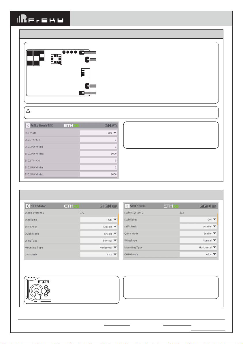
Both R6Mini-E & SR6Mini-E receivers integrate dual 5A brushed ESC function, and the speed control can be
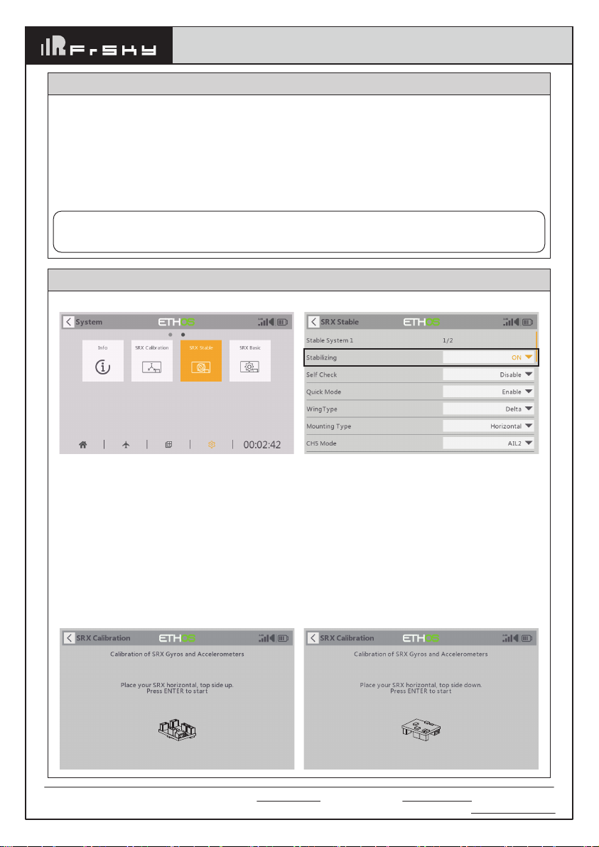
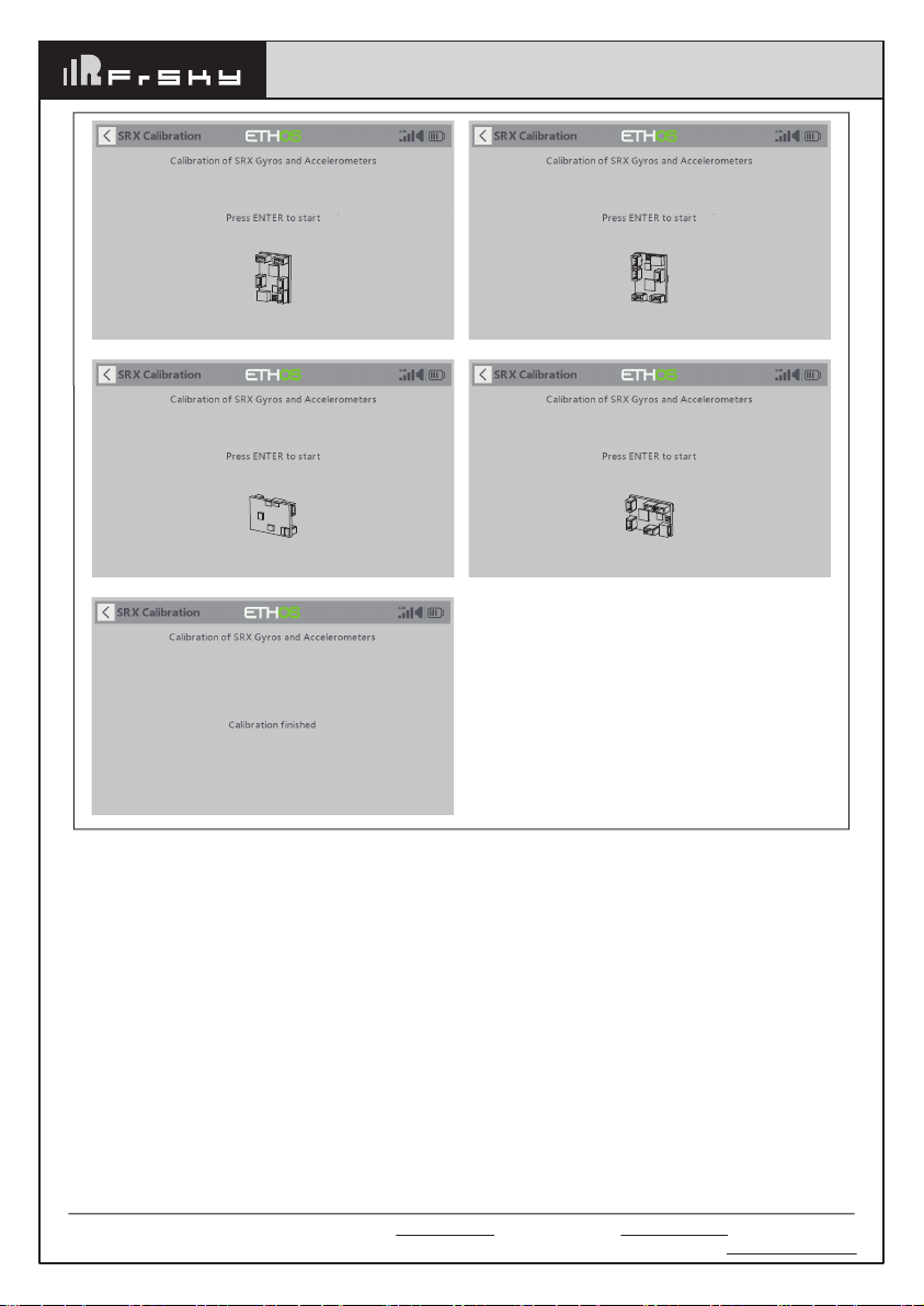
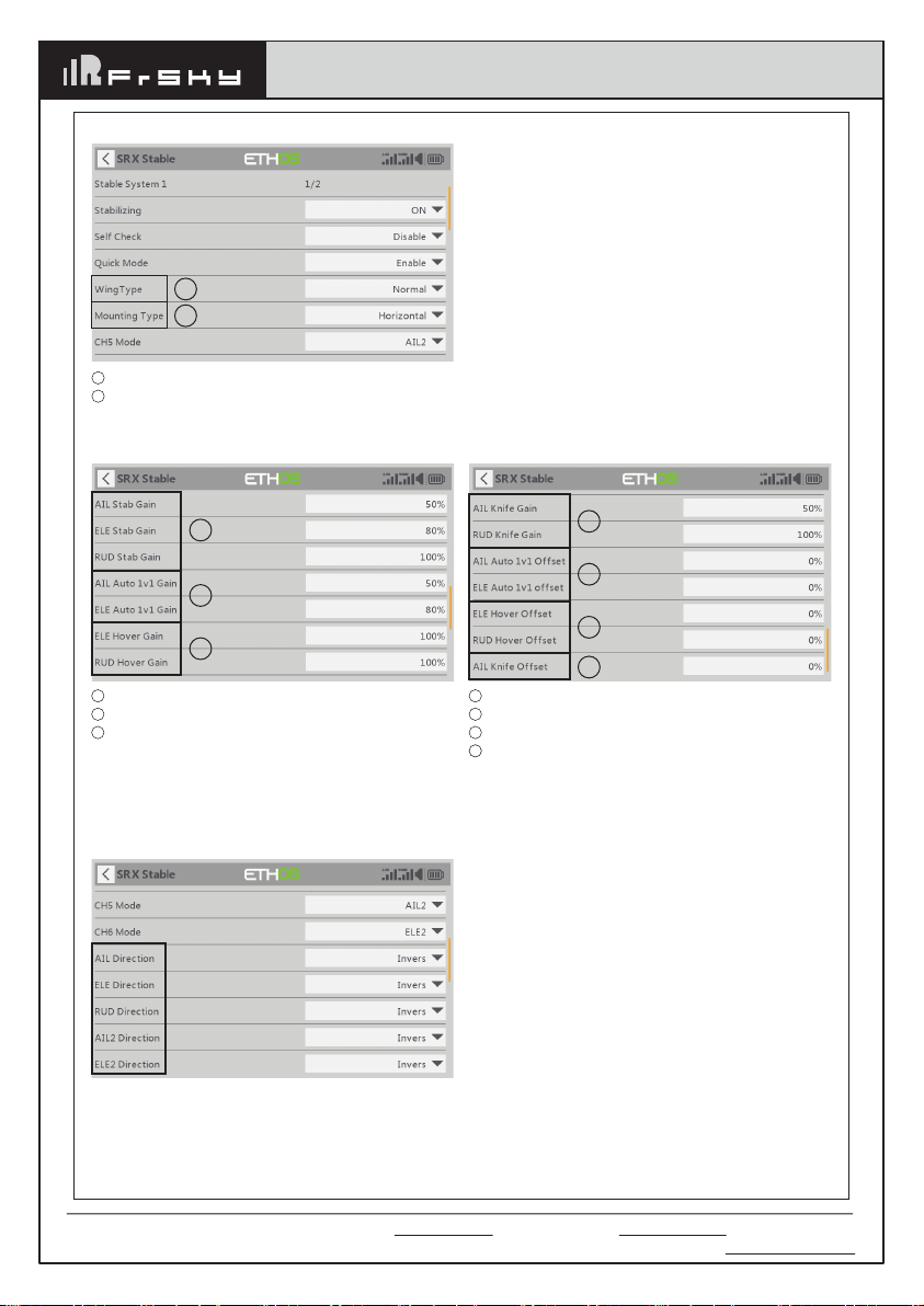
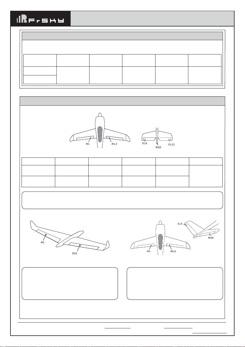
easily applied to the motors in connection. Additionally, the SR6Mini & SR6Mini-E receivers are gyro-stabilized
receivers with a built-in 3-axis gyroscope and 3-axis accelerometer and feature multiple flight modes (Auto-level,
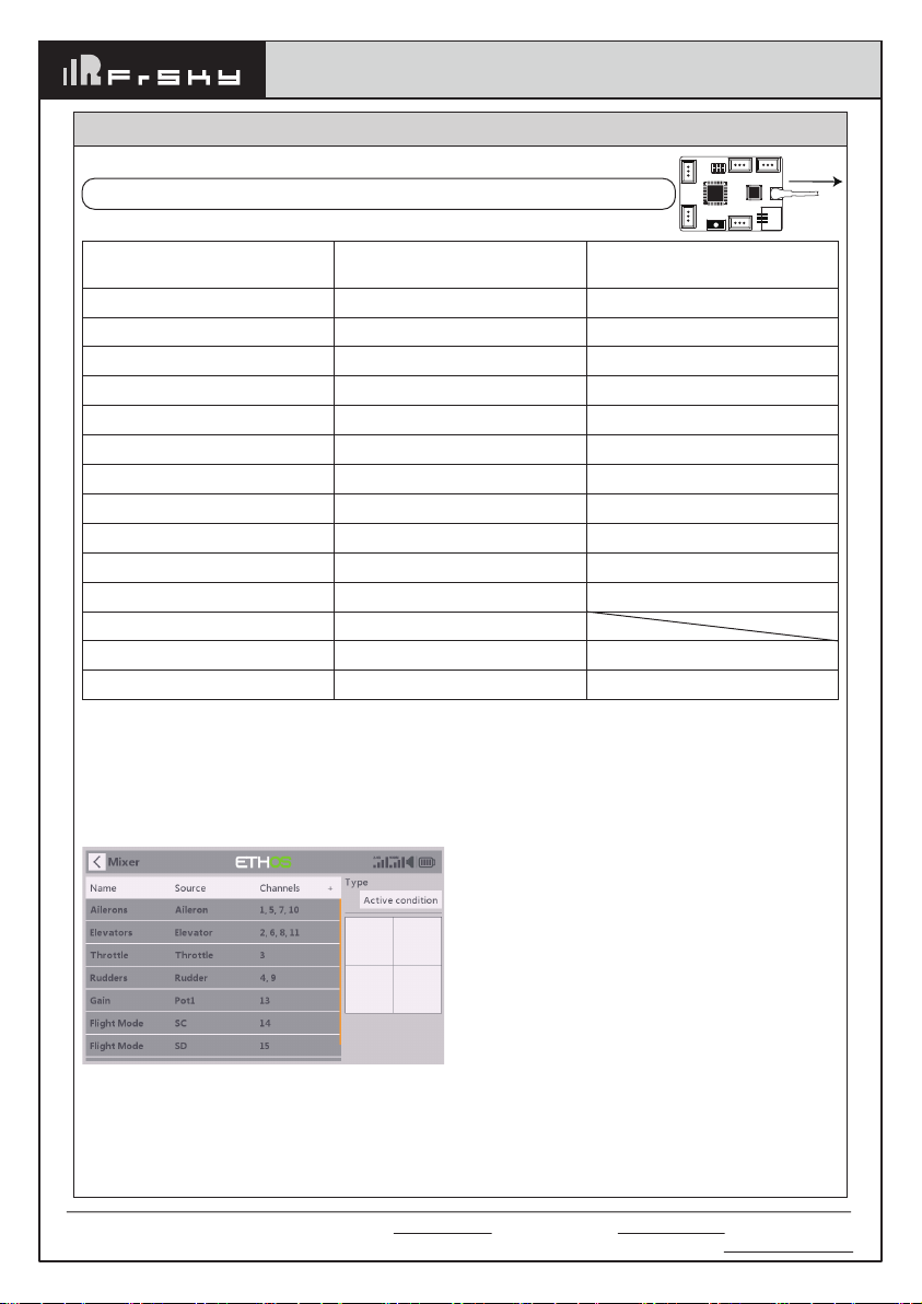
Stabilization, Knife-Edge, etc.). The stabilization mode has been enhanced with 5 additional stabilization
channels, providing pin mapping to each channel in the multiple flight modes.
(*Some features require the support of ACCESS and ETHOS.)
Overview
CH3CH2
CH1
CH4 CH5
UPGRADE
S.PORT
ANT
LED
BUTTON
CH6
16mm
22mm
ESC 1
ESC 2

Instruction Manual for FrSky
ARCHER PLUS R6Mini | R6Mini-E | SR6Mini | SR6Mini-E Receiver
Add: F-4,Building C, Zhongxiu Technology Park, No.3 Yuanxi Road, Wuxi, 214125, Jiangsu, China Technical Support: [email protected]
Features
● Enhanced Anti-RF-Interference Capability with More Solid RF Performance
● Small and Lightweight
● 6 High-Precision PWM Output Channel Ports
● S.Port / F.Port / FBUS (Configurable via S.Port)
● Over-The-Air (OTA) FW update
● Smart-Matched ACCESS & ACCST D16 Modes
● Supports Stabilization Function (SR6Mini / SR6Mini-E)
● Integrated Dual 5A Brushed ESC for Brushed Motor (R6Mini-E / SR6Mini-E)
LED Status (ACCESS)
Green LED
On
Flash
On
On
On
Off
Red LED
On
Flash
On
Off
Off
On
Status
Register
Register successfully
Bind
Bind successfully
In working
Failsafe
Blue LED
ON
Flashing
OFF
Blue LED
Flashing
Status (Self-check)
Center detection of channel in progress
Max & Min of channels in detecting
Self-check is completed
Calibration of Accelerometer
Calibration is completed
Follow the step below to finish the registration & binding procedure:
1. For TANDEM X20 as an example, enter into the Model, select RF System, turn on the internal module, select
status [ON] and ACCESS, Then determine the antennas (internal or external) and choose the RF power
according to the actual usage, the ACCESS receiver can be registered to the radio at the moment. (Notice: the
"Registration" process is not required while binding the receiver in ACCST D16 mode.)
2. Connect the battery to the receiver while holding the button on the receiver. The RED LED and GREEN LED
on the receiver will be on, indicating into the [Reg] status.
3. When it shows the Register ID, RX name and UID, click [Register]. The RED LED and GREEN LED on the
receiver will flash, and the transmitter displays [Registration OK ].
4. Power off the receiver.
5. Move the cursor to select any one of the 3 receivers and press [Bind].
6. Connect the battery to the receiver.
7. Select the RX, the GREEN will keep lit, then the transmitter displays [Bind successful].
Registration & Automatic Binding
Note: Once the receiver is registered, the button is not needed anymore in the binding process (ACCESS mode).

Instruction Manual for FrSky
ARCHER PLUS R6Mini | R6Mini-E | SR6Mini | SR6Mini-E Receiver
Add: F-4,Building C, Zhongxiu Technology Park, No.3 Yuanxi Road, Wuxi, 214125, Jiangsu, China Technical Support: [email protected]
Two independent stabilizing functions (ARCHER PLUS SR6Mini | SR6Mini-E)
Option 1: The "Stable System 1" allows turning on/off
the first group of stabilization channels (CH1-6);
Option 2: The "Stable System 2" allows turning on/off
the second group of stabilization channels (CH7-11);.
DISP
MDL
Note: Pressing the center button
of the left navigation menu
buttons, users can switch to the
second configuration page of
stabilization channels.
Note: The settings for Stable System 1 and 2
are independent, Stab calibration and
self-check should be completed for both stab
systems.
Ensure the receiver is bound to the radio and
enable the ESC status, then the data are
readable through Lua script. The script
supports configuring the output channel, and
Min&Max values for dual ESC.
Dual 5A Brushed ESC (ARCHER PLUS R6Mini-E | SR6Mini-E)
Make sure the [Brush ESC] script tool has been downloaded and placed in the [Scripts] folder of the
storage card. The tool can be found under the [System] menu page after rebooting the ETHOS system.
Please reverse the wire connections if the rotation direction of motors is not correct.
CH6
Motor 1
Motor 2
Diagram with Dual Motor Connected

Instruction Manual for FrSky
ARCHER PLUS R6Mini | R6Mini-E | SR6Mini | SR6Mini-E Receiver
Add: F-4,Building C, Zhongxiu Technology Park, No.3 Yuanxi Road, Wuxi, 214125, Jiangsu, China Technical Support: [email protected]
Basic Step Guides-Stabilization Function (ARCHER PLUS SR6Mini | SR6Mini-E)
a. Model Creation & Make sure the connected receiver is bound to the radio;
b. Ensure stabilization is enabled & Calibrate the gyroscope sensor of the device;
c. Servo connection & Build the stabilization device to the model;
d. Set up the mixer channel and radio switches;
e. Determine the [Wing Type] & [Mounting Type];
f. Check the stabilized channel outputs of the receiver in the Auto-Level mode;
g. Check the stick control of the transmitter in the manual mode;
h. Self-Check of the receiver;
I. Failsafe setting.
Note: Please move to the [DOWNLOAD] section from the product page to download the functional Lua
scripts (Place the decompressed folder in the root directory of the [Scripts] folder on the memory
card to use.)
Move to [SRX Calibration] tool and calibrate the gyroscope sensor
1. The gyroscope of device (6 surfaces) must be calibrated before mounting into the model. Please place the
device on a flat ground or a table, and follow the instruction steps below to calibrate the gyrosope sensor;
2. Make sure the stabilization device with the button side facing upwards laying on the desktop, move to the
radio and enter the [SRX Calibration] tool, and select "click to confirm". At this moment, the yellow LED light
will flash until it lits off, then follow the prompts to calibrate the sensor;
3. Complete the calibration of all the device surfaces. Ensure the values of each axis (X, Y, Z, Mod) is about
1.000 while placing the device in the corresponding direction, and the deviation could be within ±0.1;
4. The calibration is completed if all the steps above are done.
Gyroscope Sensor Calibration (ARCHER PLUS SR6Mini | SR6Mini-E)
[System] → [SRX Stable] [SRX Stable] → [Stabilizing] → [On]
Ensure the ARCHER PLUS SR6Mini | SR6Mini-E stabilization function is enabled.

Place your SRX vertical, antenna down Place your SRX vertical, antenna up
Place your SRX CH3/4/5 connector side upPlace your SRX CH3/4/5 connector side down
Add: F-4,Building C, Zhongxiu Technology Park, No.3 Yuanxi Road, Wuxi, 214125, Jiangsu, China Technical Support: [email protected]
Instruction Manual for FrSky
ARCHER PLUS R6Mini | R6Mini-E | SR6Mini | SR6Mini-E Receiver

Add: F-4,Building C, Zhongxiu Technology Park, No.3 Yuanxi Road, Wuxi, 214125, Jiangsu, China Technical Support: [email protected]
Number of Channel
CH1
CH2
CH3
CH4
CH5
CH6
CH7
CH8
CH9
CH10
CH11
CH12
CH13
CH14&CH15
Corresponding parts
on the model
AIL 1
ELE 1
THR
RUD
AIL 2
ELE 2
AIL 3
ELE 3
RUD 2
AIL 4
ELE 4
User-defined
User-defined
User-defined
Full name
Aileron
Elevator
Throttle
Rudder
Aileron
Elevator
Aileron
Elevator
Rudder
Aileron
Elevator
Gyro gain adjustment
Flight modes
Gyro gain adjustment of CH13: When the the value of CH13 is in the center, the gain is zero. The gain increases
as the value get bigger. Until the value is ±100%, the gain reaches maximum.
Attentions
CH1~CH12 should be connected to the corresponding servos.
Set up the mixer channel and radio switches
Refer to the Channel List to set the channel and switches. The switch setting of CH13-15 on the picture is for
reference.
1. Connect the servos to the ports of the stabilization device according to the Channel List.
Servo connection & Build the device to the model (ARCHER PLUS SR6Mini | SR6Mini-E)
Note:
Please make sure the receiver antenna forwards the nose direction.
Instruction Manual for FrSky
ARCHER PLUS R6Mini | R6Mini-E | SR6Mini | SR6Mini-E Receiver
Forward
CH3CH2
CH1
CH4 CH5
UPGRADE
S.PORT
ANT

Add: F-4,Building C, Zhongxiu Technology Park, No.3 Yuanxi Road, Wuxi, 214125, Jiangsu, China Technical Support: [email protected]
3. [Gain] and [Offset] configurations of flight modes
3
2
1
Gain - Stab Mode
Gain - Auto-Level Mode
Gain - Hover Mode
1
2
3
2
1
4
3
4
1
2
3
Gain - Knife Mode
Angle Offset - Auto-Level Mode
Angle Offset - Hover Mode
Angle Offset - Knife Mode
2. Move to the [SRX Stable] tool, determine the [WingType] & [Mounting Type];
4. Check whether the reaction of the wing servo is in line with the flight attitude caption below in the
[Auto-Level] mode. If not, please try to invert the corresponding channel output in the [SRX Stable]
tool.
Inspection of flight attitude
To ensure flight safety, checking the compensation direction of the model is strongly recommended.
Activating auto level mode will produce a strong deflection on AIL and ELE, which is used to check the response
of aileron and elevator. Also, activating Knife-edge and Hover mode will have the same reaction on the rudder.
1
2
Wing Type
Mounting Type
1
2
Instruction Manual for FrSky
ARCHER PLUS R6Mini | R6Mini-E | SR6Mini | SR6Mini-E Receiver

Add: F-4,Building C, Zhongxiu Technology Park, No.3 Yuanxi Road, Wuxi, 214125, Jiangsu, China Technical Support: [email protected]
When the plane is rotated up or down
(Pitch), elevators should have the correcting
actions as illustrated.
When the plane is rotated left or right (Roll),
ailerons should have the correcting actions
as illustrated.
When the plane is rotated to left or right
(Yaw), rudders should have the correcting
actions as illustrated.
5. Check whether the reaction of the wing servo is in line with the radio stick operation in the [Manual]
mode. If not, please try to invert the corresponding channel output by pressing the channel bar in the
[Output] tool.
Note:
If the compensation direction is incorrect, please reverse the corresponding channel as illustrated
above through the [SRX Stable] tool.
After changing the compensation direction, make sure to check it again on the actual model.
Instruction Manual for FrSky
ARCHER PLUS R6Mini | R6Mini-E | SR6Mini | SR6Mini-E Receiver

Add: F-4,Building C, Zhongxiu Technology Park, No.3 Yuanxi Road, Wuxi, 214125, Jiangsu, China Technical Support: [email protected]
Self Check (ARCHER PLUS SR6Mini | SR6Mini-E)
1. Make sure the model is in a horizontal position on the ground, then put the throttle to 0, and keep the other channels
in the center position.
2. Move to [
System
] and enter the [SRX Stable] tool to turn on [Self Check], then the blue LED light turns on. Once the
blue LED starts flashing, we can calibrate the maximum travel of stick channels (excluding the throttle channel).
3. If the calibration is completed, the LED turns off and the servos react left and right to indicate that the calibration
process is completed.
Note: To do the Self-Check of the stabilization device, please ensure the stabilization function is
enabled. Enter the [SRX Stable] tool and turn On the [Stabilizing], then quit the [SRX Stable] tool and
back into this tool again, now the [Self-Check] function is capable to enable.
Do the Self-Check in the [SRX Stable] tool. [System] → [SRX Stable] → [Self-Check]
How to set the flight modes (ARCHER PLUS SR6Mini | SR6Mini-E)
Quick Mode
It supports stabilization mode, auto-level mode, and manual mode (Gyroscope is off) and configured through
CH14.
Flight Mode
None
Stabilization Mode
Automatical Level Mode
Position
SW Down
SW Mid
SW Up
Channel
CH14 (3 pos SW)
Enable the Quick Mode in the [SRX Stable] tool.
Note: The default mode of ARCHER PLUS SR6Mini
| SR6Mini-E is Quick Mode.
- If Quick Mode is applied, there is no Knife
Edge or (3D) Hover Mode.
- CH15 is not used when using Quick Mode.
Instruction Manual for FrSky
ARCHER PLUS R6Mini | R6Mini-E | SR6Mini | SR6Mini-E Receiver

Add: F-4,Building C, Zhongxiu Technology Park, No.3 Yuanxi Road, Wuxi, 214125, Jiangsu, China Technical Support: [email protected]
Delta wing & Flying wing & V-tail
CH14 SW-Mid
Off
CH14 (3 pos SW)
CH15 (3 pos SW)
Stabilization
CH14>M+H
(CH14 SW Down)
M-H<CH15<M+H
(CH15 SW Mid)
Automatic level
CH14>M+H
(CH14 SW Down)
CH15>M+H
(CH15 SW Down)
Hover
CH14>M+H
(CH14 SW Down)
CH15<M-H
(CH15 SW Up)
Knife-Edge
CH14<M-H
(CH14 SW Up)
M-H<CH15<M+H
(CH15 SW Mid)
Flight mode
Note: M:
represents a neutral signal period (1500μs)
H:
represents the time of required signal change to activate the mode (50μs). When the factory settings
are selected, the switch position shown above represents the required modes.
Conventional Model
Model Configuration Reference (ARCHER PLUS SR6Mini | SR6Mini-E)
Layout
Conventional Mode
It supports stabilization mode and manual mode
(Gyroscope is off)
and configured through CH14&15. The
precise configuration is Written below.
CH14 SW-Mid
Off
CH14 SW Down
&
CH15 SW Mid
Stabilization
CH14 SW Down
&
CH15 SW Down
Automatic
level
CH14 SW Down
&
CH15 SW Up
Hover
CH14 SW Up
&
CH15 SW Mid
Knife-Edge
CH14 (3 pos SW)
CH15 (3 pos SW)
Flight mode
Instruction Manual for FrSky
ARCHER PLUS R6Mini | R6Mini-E | SR6Mini | SR6Mini-E Receiver
Layout of Delta wing / Flying wing
When Delta wing/Flying wing is selected, the signal
produced by the transmitter should be without
active mixes on the channels related to AIL and
ELE. ARCHER PLUS SR6Mini | SR6Mini-E will mix
the AIL (CH1) and ELE (CH2) input signal with a
fixed mix percentage automatically.
Layout of V-tail
When V-tail type is selected, the signal produced
by the transmitter should be without active mixes
on the channels related to ELE and RUD. ARCHER
PLUS SR6Mini | SR6Mini-E will mix the ELE (CH2)
and RUD (CH4) input signal with a fixed mix
percentage automatically.

Add: F-4,Building C, Zhongxiu Technology Park, No.3 Yuanxi Road, Wuxi, 214125, Jiangsu, China Technical Support: [email protected]
Flight mode Stabilization Auto Level Off
CH14 CH14>M+H
(CH14 SW Down)
CH14<M-H
(CH14 SW Up) CH14 SW-Mid
The available flight modes can be assigned to CH14 with a three-position switch.
Instruction Manual for FrSky
ARCHER PLUS R6Mini | R6Mini-E | SR6Mini | SR6Mini-E Receiver
Stabilization:
When the model is activated, ARCHER PLUS SR6Mini | SR6Mini-E will compensate with external
forces (wind) as soon as receiving commands from the transmitter. This function is used to enhance the stability
of the model on three axis (Pitch, Roll, YAW). CH13 could be used to adjust gyro gain by assigning a knob or a
slider, changing the sensitivity of the counteracting signal produced by the internal three-axis gyroscope.
Automatic level:
When the mode is activated, ARCHER PLUS SR6Mini | SR6Mini-E will make the model return
to level orientation with internal three-axis accelerometer and three-axis gyroscope on AIL and ELE channels
after the sticks being released to neutral. RUD channel works in stabilization mode only.
Hover:
When the mode is activated, ARCHER PLUS SR6Mini | SR6Mini-E will make the nose of the model
straight up with internal three-axis accelerometer and three-axis gyroscope on RUD and ELE channels (ELE and
RUD inputs are not required). Under this mode, AIL is used to control the rotation of the model and THR adjust
the altitude. AIL channel works in stabilization mode only.
Knife-egde mode:
When the mode is activated, ARCHER PLUS SR6Mini | SR6Mini-E will roll the plane on a
certain side (wing points up) with internal three-axis accelerometer and three-axis gyroscope on RUD and AIL
channels.Thus, AIL inputs are not required. While the mode steering is done with ELE, altitude will be maintained
with THR/RUD. ELE channel operates in stabilization mode only.
Off:
When the mode is activated, ARCHER PLUS SR6Mini | SR6Mini-E will transmit the received commands
produced by the transmitter to the model without compensating.
Configuration for the Movement Range of the Roll and Pitch Angle in Stab Mode (SR6Mini | SR6Mini-E)
Make sure the [SRX Stable] script tool has been downloaded and placed in the [Scripts] folder of the
storage card. The tool can be found under the [System] menu page after rebooting the ETHOS system.
This feature will not be activated if the degree is
set to 0. Additionally, the angle values are not
recommended to be set too small for the actual
usage.
Ensure the receiver is bound to the radio and its
Stab data is readable through Lua script. The
movement angle of Roll and Pitch for Stab mode
can be configured up to 80 degrees.

Add: F-4,Building C, Zhongxiu Technology Park, No.3 Yuanxi Road, Wuxi, 214125, Jiangsu, China Technical Support: [email protected]
Instruction Manual for FrSky
ARCHER PLUS R6Mini | R6Mini-E | SR6Mini | SR6Mini-E Receiver
How to Switch High PWM Speed mode
1. The factory default setting is OFF .
2. To go to the receiver [Options], select On to active high speed mode .
Warning: High PWM speed mode is only applied for digital servos. Turn off High PWM Speed mode
when using analog servo, otherwise servos will get hot and may burn out.
How to switch the S.Port/F.Port/FBUS
Click the Telem.Port, and select S.Port/F.Port/FBUS.
Enter into RX Settings.
Note: Please do not do the binding operation in the near range while the firmware upgrading in progress.
Note: Update the firmware after the receiver getting registered (OTA).
Go to the [File manager], and select the FW, press the enter button, select [Flash RX by int.OTA]. Power on the
receiver, select the RX, go to the [ENTER], complete the flash process, the transmitter will display [Success].
Wait for 3 seconds, the receiver works properly at the moment.
About OTA function

Add: F-4,Building C, Zhongxiu Technology Park, No.3 Yuanxi Road, Wuxi, 214125, Jiangsu, China Technical Support: [email protected]
Instruction Manual for FrSky
ARCHER PLUS R6Mini | R6Mini-E | SR6Mini | SR6Mini-E Receiver
A pre-flight range check should be done before every flight, in case the signal loss is caused by the reflection of
the signal by the nearby metal fence or concrete, and the shading of the signal by buildings or trees during the
actual flight.
1. Place the model at least 60 cm (2 feet) above the non-metal contaminated ground (such as on a wooden
bench). The receiving antenna should be in a vertical position.
2. Ener the ETHOS system, move to the "RF System", scroll the Encoder to select "RANGE" mode and press
Encoder. In range check mode, the effective distance will be decreased to 1/30.
Range Check
There are 3 failsafe modes when the setting is enabled: No Pulse, Hold, and Custom mode.
●
No Pulses Mode: On loss of signal, the receiver produces no pulses on any pwm channel. To use this mode,
select it in the menu and wait 9 seconds for the failsafe to take effect.
●
Hold Mode: The receiver continues to output the last positions before the signal was lost. To use this mode,
select it in the menu and wait 9 seconds for the failsafe to take effect.
●
Custom Mode: Pre-set to required positions on the lost signal. Move the cursor to the failsafe mode of the
channel and press Encoder, then choose the Custom mode. Move the cursor to the channel you want to set
failsafe On and press Encoder. Then rotate the Encoder to set your failsafe for each channel and short-press
the Encoder to finish the setting. Wait 9 seconds for the failsafe to take effect.
How to set Failsafe
Note:
●
If the failsafe is not set, the model will always work with the last working status before the signal is
lost. That could cause potential damage.
●
When the failsafe is disabled on the RF module side, the receiver defaults to Hold mode.
●
When in No Pulses Mode, do not set the Failsafe to No Pulses Mode for the SBUS port as it will keep
the signal output continuously,Please set "Hold" or "Custom" mode for the SBUS port.

FrSky is continuously adding features and improvements to our products. To get the most from your product, please check
the download section of the FrSky website www.frsky-rc.com for the latest update firmware and manuals
Add: F-4,Building C, Zhongxiu Technology Park, No.3 Yuanxi Road, Wuxi, 214125, Jiangsu, China Technical Support: [email protected]
Instruction Manual for FrSky
ARCHER PLUS R6Mini | R6Mini-E | SR6Mini | SR6Mini-E Receiver
1. This device complies with Part 15 of the FCC Rules. Operation is subject to the following two conditions:
1) This device may not cause harmful interference.
2) This device must accept any interference received, including interference that may cause undesired
operation.
2. Changes or modifications not expressly approved by the party responsible for compliance could void the
user's authority to operate the equipment.
NOTE: This equipment has been tested and found to comply with the limits for a Class B digital device, pursuant
to Part 15 of the FCC Rules. These limits are designed to provide reasonable protection against harmful interfer-
ence in a residential installation. This equipment generates uses and can radiate transmitter frequency energy
and, if not installed and used in accordance with the instructions, may cause harmful interference to transmitter
communications. However, there is no guarantee that interference will not occur in a particular installation. If this
equipment does cause harmful interference to transmitter or television reception, which can be determined by
turning the equipment off and on, the user is encouraged to try to correct the interference by one or more of the
following measures:
- Reorient or relocate the receiving antenna.
- Increase the separation between the equipment and receiver.
- Connect the equipment into an outlet on a circuit different from that to which the receiver is connected.
- Consult the dealer or an experienced transmitter/TV technician for help.
FCC STATEMENT
This manual suits for next models
3
Table of contents
Other FrSky Receiver manuals

FrSky
FrSky R9 User manual

FrSky
FrSky Delta 8 User manual

FrSky
FrSky ARCHER PLUS Series User manual

FrSky
FrSky RX8R PRO User manual

FrSky
FrSky S6R User manual

FrSky
FrSky TD R18 User manual

FrSky
FrSky TANDEM X20 Series User manual

FrSky
FrSky ARCHER SR6 User manual

FrSky
FrSky RX6R User manual

FrSky
FrSky ACCESS RX4R User manual

FrSky
FrSky TD R10 User manual

FrSky
FrSky XJT User manual

FrSky
FrSky ARCHER PLUS SR10+ User manual

FrSky
FrSky D4R-II User manual

FrSky
FrSky TWIN Series User manual

FrSky
FrSky ACCST G-RX6 User manual

FrSky
FrSky D8RSP User manual

FrSky
FrSky RX6R User manual

FrSky
FrSky HORUS X10 User manual

FrSky
FrSky ACCESS G-RX6 User manual