F5 520 User manual

Platform Guide: 520/540
MAN-0067-00


F5 Networks, Inc. Platform Guide i
Product Version
This manual applies to hardware platforms 520 and 540 created by F5 Networks, Inc..
Legal Notices
Copyright
Copyright© 2002, F5 Networks, Inc. All rights reserved.
F5 Networks, Inc. (F5) believes the information it furnishes to be accurate and reliable. However, F5
assumes no responsibility for the use of this information, nor any infringement of patents or other rights of
third parties which may result from its use. No license is granted by implication or otherwise under any
patent, copyright, or other intellectual property right of F5 except as specifically described herein.
F5 reserves the right to change specifications at any time without notice.
Trademarks
F5, F5 Networks, the F5 logo, BIG-IP, 3-DNS, iControl, GLOBAL-SITE, SEE-IT, EDGE-FX, FireGuard,
Internet Control Architecture, and IP Application Switch are registered trademarks or trademarks of F5
Networks, Inc. in the U.S. and certain other countries. All other product and company names are registered
trademarks or trademarks of their respective holders. F5 trademarks may not be used in connection with
any product or service except as permitted in writing by F5.
Patents
This product protected by U.S. Patent 6,374,300; Pending U.S. Patent 20020040400. Other patents
pending.
Export Regulation Notice
This product may include cryptographic software. Under the Export Administration Act, the United States
government may consider it a criminal offense to export this product from the United States.
Export Warning
This is a Class A product. In a domestic environment this product may cause radio interference in which
case the user may be required to take adequate measures.
FCC Compliance
This equipment generates, uses, and may emit radio frequency energy. The equipment has been type tested
and found to comply with the limits for a Class A digital device pursuant to Part 15 of FCC rules, which
are designed to provide reasonable protection against such radio frequency interference.
Operation of this equipment in a residential area may cause interference, in which case the user at his own
expense will be required to take whatever measures may be required to correct the interference.
Any modifications to this device, unless expressly approved by the manufacturer, can void the user's
authority to operate this equipment under part 15 of the FCC rules.
Canadian Regulatory Compliance
This class A digital apparatus complies with Canadian I CES-003.
Standards Compliance
The product conforms to ANSI/UL Std 1950 and Certified to CAN/CSA Std. C22.2 No. 950.

ii


Table of Contents
F5 Networks, Inc., Platform Guide iii
1
Introducing the 520/540 Platform
Reviewing the 520/540 platform .................................................................................................1-1
Getting started ................................................................................................................................1-2
Components provided with the controller .....................................................................1-2
Peripheral hardware that you provide ..............................................................................1-3
Familiarizing yourself with the controller ..................................................................................1-4
Using the 520/540 hardware ...............................................................................................1-4
Environmental requirements ........................................................................................................1-6
General guidelines .................................................................................................................1-6
Guidelines for DC-powered equipment ...........................................................................1-7
Installing and connecting the hardware .....................................................................................1-8
Interfaces ........................................................................................................................................ 1-10
Interface naming conventions .......................................................................................... 1-10
Displaying status and settings for interfaces ................................................................. 1-11
Media type and duplex mode ........................................................................................... 1-11
Activating the license .................................................................................................................. 1-13
Automatically activating a license .................................................................................... 1-13
Manually activating a license ............................................................................................. 1-16
Using the Setup utility ................................................................................................................. 1-18
Additional resources ................................................................................................................... 1-18
2
Configuring the FIPS 140 Hardware
Introducing FIPS 140 hardware security module support .....................................................2-1
Initializing the FIPS 140 hardware security module and creating the security world .....2-2
Creating the security world on a single unit or the primary unit of a
redundant system ...................................................................................................................2-2
Configuring the security world on the second unit in a redundant system .............2-5
Configuring multiple FIPS 140 hardware security modules in a single 520/540 ......2-7
Adding a second security module to an existing security world ................................2-9
Using the key utilities to generate keys .................................................................................. 2-11
Generating a key configuration file and a key .............................................................. 2-11
Generating a certificate request file and temporary certificate ............................... 2-13
Importing existing public keys and certificates ............................................................. 2-13
Additional configuration options .............................................................................................. 2-14
3
Additional Hardware Specifications
Reviewing hardware specifications .............................................................................................3-1
520 specifications ............................................................................................................................3-2
540 specifications ............................................................................................................................3-3
Glossary
Index
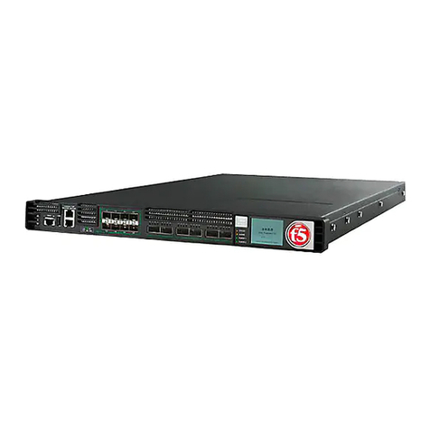
Table of Contents
iv


Introducing the 520/540 Platform
F5 Networks, Inc., Platform Guide 1 - 1
Reviewing the 520/540 platform
The 520 and 540 platforms are powerful systems capable of managing
traffic for medium to large enterprises.
Externally, the 520 and 540 platforms look the same (Figure 1.1). However,
there are internal differences. The 540 is a dual-processor platform with
more memory than the 520 platform. For details, see Reviewing hardware
specifications, on page 3-1.
Three PCI expansion slots are available on both the 540 and 520. These PCI
slots provide the option to add SSL accelerator cards, additional 10/100
network interface cards, or Gigabit Ethernet interfaces.
Figure 1.1 An example of the 520/540 platform. In this case, a BIG-IP Controller

Chapter 1
1 - 2
Getting started
There are several basic tasks you must complete to get the 520/540 platform
installed and set up.
• Review the hardware requirements.
• Familiarize yourself with the controller hardware.
• Review the environmental requirements.
• Connect the controller to the network, and optionally connect the
peripheral hardware.
• Activate the license.
The controller comes with the hardware that you need for installation and
maintenance. However, you must also provide standard peripheral
hardware, such as a keyboard or serial terminal, if you want to administer
the controller directly.
Components provided with the controller
When you unpack the controller, you should make sure that the following
components, shown in Figure 1.2, are included:
• One power cable
• Four rack-mounting screws
• Documentation and Software CD
If you purchased a hardware-based redundant system, you also received one
fail-over cable to connect the two controller units together (network-based
redundant systems do not require a fail-over cable).
Figure 1.2 Components included with the controller

Introducing the 520/540 Platform
F5 Networks, Inc., Platform Guide 1 - 3
Peripheral hardware that you provide
For each controller in the system, you need to provide the following
peripheral hardware:
◆If you plan to use direct administrative access to the controller, you need
standard input/output hardware. Either of the following options is
acceptable:
• A VGA monitor and PC/AT-compatible keyboard.
• Optionally, a serial terminal and a null modem cable. For serial
terminal configuration information, refer to the BIG-IP Reference
Guide, Chapter 3, Post-Setup Tasks in the section Using a serial
terminal with the BIG-IP system.
◆If you want to use the default controller configuration, you must have an
administrative workstation on the same IP network as the Controller.
◆You also need network hubs, switches, or concentrators to connect to the
controller network interfaces. The devices you select must be compatible
with the network interface cards installed in the controller. The devices
can support 10/100 Ethernet or Gigabit Ethernet.
• Ethernet requires either a 10 Mbps or 100 Mbps hub or switch.
• Gigabit Ethernet requires a compatible Gigabit Ethernet switch.
If you plan on doing remote administration from your own PC workstation
as most users do, we recommend that you have your workstation already in
place. Keep in mind that the Setup utility prompts you to enter your
workstation’s IP address when you set up remote administrative access.

Chapter 1
1 - 4
Familiarizing yourself with the controller
The controller is offered in 520 and 540 hardware configurations. Before
you begin to install the controller, you may want to quickly review the
following figures that illustrate the controls and ports on both the front and
the back of a 520 controller and a 540 controller.
Using the 520/540 hardware
This section describes the front and back layout of a 520/540 controller.
Figure 1.3 illustrates the front of a 520/540 controller. On the front of the
unit, you can turn the unit off and on, or you can reset the unit. You can also
view the indicator lights for hard disk access.
Note
The interfaces on every controller are labeled, so it should be clear what
each port is, no matter which hardware configuration you have purchased.
If you have a special hardware configuration, such as one that includes more
than two interfaces, the ports on the back of your unit differ slightly from
those shown in Figure 1.4, on page 1-6.
Table 1.1 describes the behavior of the LEDs in normal startup and in error
conditions.
1. Reset button
2. Netboot button
3. Status LEDs
Figure 1.3 Front view of a 520/540 controller

Introducing the 520/540 Platform
F5 Networks, Inc., Platform Guide 1 - 5
Description Power LED Status LED Activity LED Alarm LED
Normal Startup:
Power is off Black Black Black Black
Starting Up - BIOS Green Black Black Yellow
Starting Up - Loader Green Black Yellow Yellow
Starting Up - Kernel Green Blink
Yellow Flicker Yellow* for
storage device Yellow
System ready - (standby mode) Green Yellow FlickerGreen**for
Traffic Black
System ready - (active mode) Green Green Flicker Green for
Traffic Black
Error Conditions:
Overtemp or fan failure Green Yellow or
Green Flicker Green for
Traffic Blink Red
Out of memory or other serious condition Green Yellow or
Green Flicker Green for
Traffic Red
One or more virtual servers have all nodes
down Green Yellow or
Green Flicker Green for
Traffic Blink Yellow
One or more health monitors failed Green Yellow or
Green Flicker Green for
Traffic Yellow
Self Test Failed in Phase 1 Green Black Black Red
Self Test Failed in Phase 2 Green Black Black Black
Self Test Failed in Phase 3 Green Blink Yellow Black Red
*After startup, LED3 never flickers yellow, even though the storage device may be accessed.
**Flicker Green means traffic is being load balanced or routed.
Table 1.1 Behavior of the status LEDs

Chapter 1
1 - 6
Figure 1.4, following, illustrates the back of a 520/540 controller. Note that
all ports are labeled, even those which are not intended to be used. Ports
marked with an asterisk (*) in the list following do not need to be connected
to any peripheral hardware.
*Not to be connected to any peripheral hardware.
Figure 1.4 Back view of a 520/540 controller
Environmental requirements
Before you install the controller, review the following guidelines to make
sure that you are installing and using the controller in the appropriate
environment.
General guidelines
A controller is an industrial network appliance, designed to be mounted in a
standard 19-inch rack. To ensure safe installation and operation of the unit:
• Install the rack according to the manufacturer’s instructions, and check
the rack for stability before placing equipment in it.
• Build and position the rack so that once you install the controller, the
power supply and the vents on both the front and back of the unit remain
unobstructed. The controller must have adequate ventilation around the
unit at all times.
• Do not allow the air temperature in the room to exceed 40° C.
• Do not plug the unit into a branch circuit shared by more electronic
equipment than the circuit is designed to manage safely at one time.
1. Fan
2. Power in
3. Mouse port*
4. Keyboard port
5. Universal serial bus ports*
6. Serial terminal port
7. Fail-over port
8. Video (VGA) port
9. Net1 interface (1.1)
10. Net2 interface (1.2)
11. On/off button
12 PCI expansion slots

Introducing the 520/540 Platform
F5 Networks, Inc., Platform Guide 1 - 7
• Verify that the voltage selector is set appropriately before connecting the
power cable to the unit.
Guidelines for DC-powered equipment
A DC-powered installation must meet the following requirements:
• Install the unit using a 20 Amp external branch circuit protection device.
• For permanently connected equipment, incorporate a readily accessible
disconnect in the fixed wiring.
• Use only copper conductors.
The unit must be connected to Earth ground, and it
should have a reliable ground path maintained at all
times.
!
The controller contains a lithium battery. There is danger
of an explosion if you replace the lithium battery
incorrectly. We recommend that you replace the battery
only with the same type of battery originally installed in
the unit, or with an equivalent type recommended by the
battery manufacturer. Be sure to discard all used
batteries according to the manufacturer’s instructions.
This equipment is not intended for operator
serviceability. To prevent injury and to preserve the
manufacturer’s warranty, allow only qualified service
personnel to service the equipment.
Install DC powered equipment only in restricted access
areas, such as dedicated equipment rooms, equipment
closets, or similar locations.

Chapter 1
1 - 8
Installing and connecting the hardware
There are two basic tasks required to install the hardware. You simply need
to install the controller in a rack, and then connect the peripheral hardware
and the interfaces.
WARNING
Do not turn on a controller until all peripheral hardware is connected to the
unit.
To install the hardware in a rack
1. Lift the unit into place. This requires more than one person.
2. Secure the unit using the four rack-mounting screws that are
provided.
Figure 1.5 shows the orientation of the controller and the mounting
screws for installation in a standard 19" rack. Figure 1.6 shows the
controller installed in the rack.
Figure 1.5 Platform orientation for rack mounting

Introducing the 520/540 Platform
F5 Networks, Inc., Platform Guide 1 - 9
Figure 1.6 Platform installed in a 19" rack
To connect the cables and hardware for input/output
1. Connect the hardware that you have chosen to use for input/output:
• If you are using a VGA monitor and keyboard, connect the
monitor connector cable to the video port (number 8 in Figure
1.4), and connect the keyboard connector cable to the keyboard
port (number 4 in Figure 1.4).
• Optionally, if you are using a serial terminal as the console,
connect the serial cable to the terminal serial port (number 6 in
Figure 1.4). In this case, you should not connect a keyboard to the
controller. If there is no keyboard connected to the controller
when it is started or rebooted, the controller defaults to using the
serial port as the console.
2. Connect the interface labeled Net1 (number 9 in Figure 1.4) to the
network from which the controller receives connection requests.
If you have purchased a unit with three or more network interface
cards (NICs), be sure to note or write down how you connect the
cables to the interfaces. When you run the Setup utility, it
automatically detects the number of interfaces that are installed, and

Chapter 1
1 - 10
prompts you to configure more external interfaces if you want. It is
important to select the correct interfaces based on the way you have
connected the cables to the back of the unit. For more information
about interfaces, see Interfaces, following.
3. Connect the interface labeled Net2 (number 10 in Figure 1.4) to the
network that houses the array of servers, routers, or firewalls that
the controller load balances.
4. If you have a hardware-based redundant system, connect the
fail-over cable to the fail-over port on each unit (number 7 in Figure
1.4).
5. Connect the power cable to the controller power in (number 2 in
Figure 1.4), and then connect it to the power source.
Interfaces
This platform can have as few as one network interface. It is helpful to
understand interface naming conventions before you perform configuration
tasks such as displaying interface status and settings, setting the media type,
and setting the duplex mode.
Interface naming conventions
By convention, the Ethernet interfaces on the platform take the name
<s>.<p>, where s is the slot number of the NIC, and pis the port number on
the NIC. As shown in Figure 1.7, for the 520/540 platform, slot numbering
is top-to-bottom, and port numbering is left-to-right. Note that slot 1
contains the two onboard NICs numbered 1.1 and 1.2. The numbers 2, 3,
and 4in Figure 1.7 illustrate the slot numbering for the PCI expansion slots.
For example, if you installed a single port NIC in the PCI slot marked 2, the
port number would be 2.1.
Figure 1.7 520/540 platform slot and port numbering
This manual suits for next models
1
Table of contents
Other F5 Network Hardware manuals

F5
F5 WANJet 300 Technical manual

F5
F5 BIG-IP 3900 User manual

F5
F5 Herculon SSL Orchestrator Manual

F5
F5 8900 Assembly Instructions

F5
F5 i4000 Series Assembly Instructions

F5
F5 i15000 Series User instructions

F5
F5 BIG-IP 11050 User manual

F5
F5 BIG-IP 1600 Assembly Instructions

F5
F5 ARX-500 Manual

F5
F5 6900 User manual
Popular Network Hardware manuals by other brands

Lowrance
Lowrance General information Pamplet General information

SS Telecoms
SS Telecoms SS-10 3G installation manual

Huawei
Huawei FusionPower6000 3.0 user manual

Infolock
Infolock INSIGHT DLP SENSOR 0310S Hardware installation guide

ATEN
ATEN SN0108A user manual

Infoblox
Infoblox Trinzic TE-2205 installation guide