FS Fiberstore S8050-20Q4C User manual

Fiberstore S8050 Series Switch
Installation Guide


Contents
Chapter 1 Product Introduction …………………………………………………..…………………………………………………..…...
1.1 Product Model …………………………..…………………………………………………..………..……….……….………
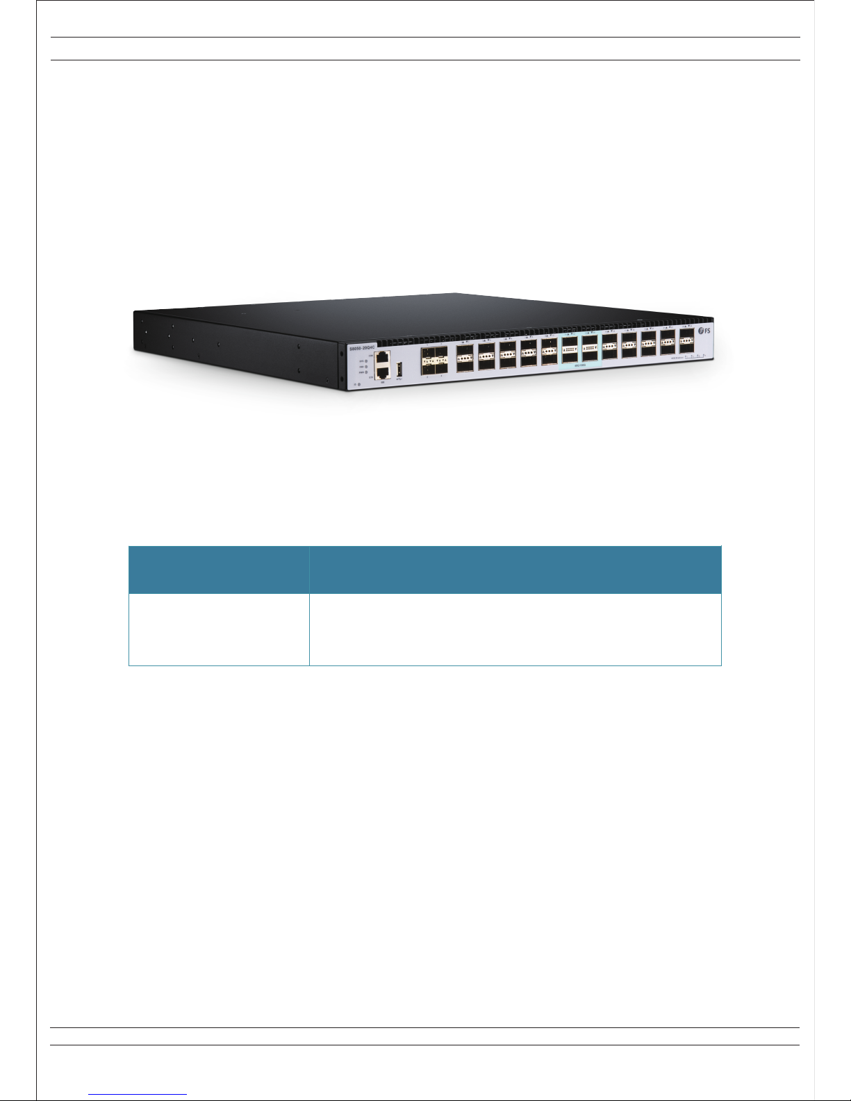
1.2 Front Panel (S8050-20Q4C)………………………………………………..………………………………………………
1.3 Rear Panel (S8050-20Q4C)…………………………………………………..………………………………………….....
1.4 FS S8050 Series Switch LED Introduction ………………………………………..………………………………...
1.4.1 System LED Indicator ……………………………………………………..……………………………………....……..
1.4.2 FAN LED Indicator ……………………………………………………..…………………………………………………..
1.4.3 Power Supply LED Indicator ……………………………………………………..……………………………………
1.4.4 Ethernet Management Interface LED Indicator ……………………………..…………………………………
1.4.5 40G QSFP+ Indicator ……………………………………………………..………………………………………………
1.4.6 100G QSFP28 Indicator ……………………………………………………..…………………………………………...
Chapter 2 Switch Installation ……………………………………………..………………………………………………………………....
2.1 Preparation for Installation ……………………………………………………..………………………………………....
2.1.1 Safety Precaution ……………………………………………………..……………………………………………………
2.1.2 Installation Site ………………………………………………..…………………………………………………………….
2.1.3 Installation Tools ……………………………………………………..……………………………………………………..
2.2 Installation ……………………………………………………..…………………………………………………………………
2.2.1 Introduction of Mounting Brackets ………………………………………………..………………………………...
2.2.2 Install the Switch into a Rack with Front Mounting Brackets ………..…………………………………...
2.2.3 Install the Switch on a Workbench ……………………………………………..……………………………………
2.2.4 Installation and Removal of Power Module ……………………………………..……………………………….
2.3 Grounding Connection ……………………………………………………..……………………………………………….
Chapter 3 Interface Module and Cable Connection Description ……………………………..……………………………...
3.1 Interface Module Description ……………………………………………………..……………………………………..
3.1.1 Ethernet Port ……………………………………………………..…………………………………………………………..
3.1.2 Console Port ……………………………………………………..……………………………………………………………
Chapter 4 Initial Power-on and Start-up of Switch ……………………………………………..…………………………………..
4.1 Building Configuration Platform and Connecting Cable …………..………………………………………….
4.2 Setting Terminal Parameter (Windows Super Terminal) ………………..……………………………………...
4.3 Setting Terminal Parameter (SecureCRT from VanDyke Software)………..……………………………….
4.4 Switch Power-on………………………………………………..………………………………………………………...……
Chapter 5 Switch Software Loading………………………………………………………..……………………………………………..
Chapter 6 Upgrade of Operating System ………………………………………………………..……………………………………..
Chapter 7 Maintenance and Troubleshooting ………………………………………………………..……………………………….
7.1 Loading Failure Processing …………………………………………………..………………………………………...…
7.2 User Password Lost …………………………………………………..……………………………………………………..
7.3 Power System Troubleshooting …………………………………………………..……………………………………..
7.4 Configuration SystemTroubleshooting …………………………………………..…………………………………..
INSTALLATION INSTRUCTIONS
© FS.COM 2016 FS016
I
For Technical Support: www.fs.com/service.html
1
1
2
2
3
3
3
3
4
4
4
5
5
5
5
7
7
7
8
9
9
10
11
11
11
11
12
12
12
14
15
16
17
18
18
18
18
18

List of Tables
Table 1-1 FS S8050 Series Switch Model ..……………………………………………………..…………………………………......
Table 2-1 Temperature/Humidity Requirements ………………………………………………..……………………………….…..
Table 2-2 Dust Content Requirements in Switch Room ……………………..…………………………………………………...
Table 2-3 Harmful Gas Threshold in the Equipment Room …………………………………..………………………….……...
Table 3-1 RJ-45 to DB-9 Cable Sequence ……………………………………………………..…………………………….………..
List of Figures
Figure 1-1 FS S8050 Series Switch ……………………………………………………..……………………………………………….....
Figure 1-2 Front Panel Sketch Map of S8050-20Q4C ……………………………………………………..…………………….….
Figure 1-3 Rear Panel Sketch Map of S8050-20Q4C ……………………………………………………..……………………..….
Figure 2-1 Appearance Sketch Map of Front Mounting Brackets …………………………………………………………….
Figure 2-2 Installation Sketch Map of Front Mounting Brackets ……………………………………………………..…….….
Figure 2-3 Installation Sketch Map of Front Mounting Brackets with Tray …………………………………………….….
Figure 2-4 Installation Sketch Map of the Foot Pads ……………………………………………………..……………………..….
Figure 2-5 Installation Sketch Map of AC Power Module……………………………………………………..……………….….
Figure 2-6 Removing Sketch Map of AC Power Module ……………………………………………………..……………….….
Figure 2-7 Grounding Installation Sketch Map When a Grounding Bar Is in Switch Room ………………………...
Figure 3-1 DB-9 to RJ-45 Console Cable ……………………………………………………………………………………………….
Figure 4-1 Building Local Configuration Platform Through Console Port ……………………………………………..…..
Figure 4-2 New Connection ……………………………………………………………………………………………………………...…...
Figure 4-3 Connection Port Setting ………………………………………………………………………………………………………..
Figure 4-4 HyperTerminal Window ……………………………………………………………………………………………………...….
Figure 4-5 Terminal Emulation Setting ………………………………………………………………………………………………...….
Figure 4-6 Create a New Quick Connection ………………………………………………………………………………………..…..
Figure 4-7 Serial Parameters Setting Interface (Protocol) ……………………………………………………………………..…
Figure 4-8 Serial Parameters Setting Interface (Port) ………………………………………………………………………………
Figure 4-9 Serial Display Interface …………………………………………………………………………………………………………
Figure 6-1 Upgrade Operating System ……………………………………………………………………………………………….….
II
INSTALLATION INSTRUCTIONS
© FS.COM 2016 FS016
For Technical Support: www.fs.com/service.html
1
5
6
6
11
1
2
2
7
8
8
9
9
10
10
11
12
12
13
13
14
14
14
15
15
17

Figure 1-1 FS S8050 Series Switch
Chapter 1 Product Introduction
The Fiberstore FS S8050 Series Routing Switch is a high performance Ethernet switch to meet next generation Metro, Data
Center and Enterprise network requirements. FS S8050 supports L2/L3/Data Center/Metro features. The FS S8050 comes with
complete system software with comprehensive protocols and applications to facilitate rapid service deployment and
management for both traditional L2/L3 networks and Data Center networks. FS S8050 has open API interfaces and Debian
system to achieve SDN.
The FS S8050 Series Routing Switch is cost-effective Ethernet access and aggregation platform to Enterprise, Data Center and
Metro application.
The FS S8050 Series Switch (Figure 1-1) currently includes one configuration: S8050-20Q4C.
1.1 Product Model
Page 1 of 18
INSTALLATION INSTRUCTIONS
© FS.COM 2016 FS016
For Technical Support: www.fs.com/service.html
Table 1-1 FS S8050 Series Switch Model
S8050-20Q4C
Model
Standard 1U 19’’rack mountable
20x40GE QSFP+ Ethernet Port
4x100GE QSFP28 Ethernet Port
Description

Page 2 of 18
INSTALLATION INSTRUCTIONS
© FS.COM 2016 FS016
For Technical Support: www.fs.com/service.html
1: 10G SFP+ Ethernet Ports
2: 40G QSFP+ Ethernet Ports
3: 100G QSFP28 Ethernet Ports
4: 40G/100G Ethernet Ports Breakout Status LED
5: 40G/100G Ethernet Ports Status LED
6: ID LED (Locate the Switch)
7: Management Ethernet Interface (MGMT)
8: USB Interface
9: System Status LED (SYS)
10: RJ-45 Console Port (CON)
11: Airflow Input Holes (Front to back airflow)
1: Grounding Screw
2: AC or DC FRU Power Supply Module (PS1)
3: AC or DC FRU Power Supply Module (PS2)
4: Cooling Fans
1.2 Front Panel (S8050-20Q4C)
Figure 1-2 Front Panel Sketch Map of S8050-20Q4C
1.3 Rear Panel (S8050-20Q4C)
Figure 1-3 Rear Panel Sketch Map of S8050-20Q4C
6 7 8 1
9 10
24
3
5
11
4 3 2 1

Page 3 of 18
INSTALLATION INSTRUCTIONS
© FS.COM 2016 FS016
For Technical Support: www.fs.com/service.html
1.4 FS S8050 Series Switch LED Introduction
1.4.1 System LED Indicator
1.4.2 FAN LED Indicator
1.4.3 Power Supply LED Indicator
SYS
Indicator Status Description
Green
Amber
-
On
Blinking Quickly (2Hz)
Blinking Slowly (0.5Hz)
Blinking Quickly (2Hz)
Blinking Slowly (0.5Hz)
On
Off
System is abnormality.
The system is power on but CPU is not running.
The system is normal running.
The system is in u-boot initiation.
The system is in system initiation.
The system occurs alarm or error.
No power or system is not running or
abnormality.
Indicator Status Description
FAN
Green
Amber
-
On
On
Off
The fans/fan trays are ok.
Fans are bad.
No power or fan trays are absent.
Indicator Status Description
PWR1
PWR2
Green
Amber
-
On
On
Off
On
On
Off
Green
Amber
-
Power supply is ok.
Power supply is abnormality.
Power supply is absent or single power supply is
abnormality.
Power supply is ok.
Power supply is abnormality.
Power supply is absent or single power supply is
abnormality.

Page 4 of 18
INSTALLATION INSTRUCTIONS
© FS.COM 2016 FS016
For Technical Support: www.fs.com/service.html
1.4.4 Ethernet Management Interface LED Indicator
Indicator Status Description
MGMT Green
On
Blinking
Off
Port link.
Port is receiving or transmitting packets.
Port not link.
1.4.5 40G QSFP+ Indicator
Indicator Status Description
1-10,15-24
(S8050-20Q4C) Green
On
Blinking
Off
40G port link.
40G packets are receiving or transmitting.
Port not link.
1.4.6 100G QSFP28 Indicator
Indicator Status Description
11-14(S8050-20Q4C) Green
On
Blinking
Off
100G port link.
100G packets are receiving or transmitting.
Port not link.

Page 5 of 18
INSTALLATION INSTRUCTIONS
© FS.COM 2016 FS016
For Technical Support: www.fs.com/service.html
Chapter 2 Switch Installation
2.1 Preparation for Installation
2.1.1 Safety Precaution
The following precautions should be followed to avoid equipment damage and personal injury caused by improper use.
•Power source should be removed before cleaning switches. Do not use wet rags to wipe switches and clean switches with
liquid.
•Do not place switches near water or in a wet environment, and prevent water or moisture from entering switch chassis.
•Do not place switches on an unstable case or table, since the dropping would cause serious harm to switches.
•Maintain good indoor ventilation and clear airholes of switches.
•Switches shall work normally under correct voltage, so make sure the operating voltage agrees with the voltage marked on
switches.
•To reduce the risk of electric shock, do not remove its enclosure when a switch is working, and don’t do so at will even if it
is not powered.
•Anti-static gloves must be worn when replacing interface board to prevent static electricity from damaging veneer.
2.1.2 Installation Site
To ensure a normal work environment, FS S8050 series switch should have the following requirements for workplace.
•Ensure that there are some spaces at the inlet and outlet of switch for heat dispersion of switch chassis.
•Ensure that rack and working platform have good ventilation and heat dispersion systems.
•Ensure that rack and working platform are firm enough to support the weight of a switch and its accessories for installation.
•Ensure rack and working platform are well earthed.
Temperature/Humidity Requirements
To ensure the normal work and service life of switches, certain temperature and humidity should be maintained inside switch
rooms. Longtime higher humidity inside switch rooms may easily lead to poor insulation or even electric leakage of dielec-
trics, and sometimes cause material changes in mechanical features and corrosion of metal parts; if the relative humidity is
lower, insulation pads could dry shrink to make fastening screws loose. Meanwhile, in the dry climate, lower relative humidity
could easily cause static electricity which will impose harms to the circuit of switch; higher temperature would be even more
harmful, long time high temperature would accelerate aging process of insulation materials to greatly reduce the reliability of
switches and severely affect their service life.
Table 2-1Temperature/Humidity Requirements
Item
Temperature
Humidity
FS S8050 Series
0~45℃
10%~95%
1.1 Product Model
To ensure switches maintain a long-term stable work, the installation workplace should also meet the following requirements.

Page 6 of 18
INSTALLATION INSTRUCTIONS
© FS.COM 2016 FS016
For Technical Support: www.fs.com/service.html
Cleanliness Requirements
Dust is a big hazard to the safe operation of switches. Indoor dust falling on the switch body can cause electrostatic adsorp-
tion to make poor contact of metal connectors or metal contacts. Especially when the indoor relative humidity is lower, electro-
static adsorption is easily formed, which will not only affect equipment service life, but also easily lead to communication failure.
Table 2-2 Dust Content Requirements in Switch Room
Besides dust, there are rigorous limits on the content of harmful substances that can accelerate the corrosion and aging of
metals, such as salts, acids, and sulfides in the air in the equipment room, and the equipment room must be protected
against ingression of harmful gases such as SO , H S, NH and Cl . For the specific requirement, see the following table.
Table 2-3 Harmful Gas Threshold in the Equipment Room
Electromagnetic Susceptibility
Switches may be affected by the interferences from outside the system, which will have an effect on devices through conduc-
tion of capacitance coupling, inductive coupling, electromagnetic wave radiation, common impedance (including ground
system) coupling and wires (power wire, signal wire and output signal wire, etc.). The following attentions should be paid to:
−AC power supply system is TN system, and AC power socket should be single-phase 3-wire outlet with protective earth (PE)
so that filter circuit on devices can effectively filter interference from electric grid.
−Places where switches work should be kept away from strong-power radio transmitting station, radar transmitting station,
high-frequency high-current devices.
−Electromagnetic shielding should be adopted when necessary, i.e. interface cables use shielded cables.
−Interface cables are required to be arranged indoors instead of outdoors to prevent signal ports of devices from being
damaged by over voltage and over current generated from lightning.
Laser Use Safety
−FS S8050 series switch is Class 1 laser device.
−Do not stare at the optical interfaces directly when the optional optical interfaces of FS S8050 series switch are in operating
mode, since light beam emitting from fiber has high energy which may be harmful to retina.
Substance Unit Concentration Limit
Dust Particle/m
Note: The dust particle size is ≥5 μm
≤3 X 10⁴ (No visible dust on the tabletop for three days)
Gas Maximum Concentration (mg/m )
SO20.2
H S
2
NH3
CI2
0.006
0.05
0.01
3
3
3
2 2 3 2

Page 7 of 18
INSTALLATION INSTRUCTIONS
© FS.COM 2016 FS016
For Technical Support: www.fs.com/service.html
2.1.3 Installation Tools
Prepare the following tools before installation:
•Flathead screwdriver
•Phillips screwdriver
•ESD-preventive wrist strap
2.2 Installation
FS S8050 series switch can be installed in the following 2 ways:
•Install the switch into a rack with Front Mounting Brackets (19” standard rack)
•Install the switch on a workbench
2.2.1 Introduction of Mounting Brackets
Mounting Brackets (FS S8050)
Figure 2-1 Appearance Sketch Map of Front Mounting Brackets
Description:
(1) Screw hole for fixing Front Mounting Brackets and rack
(2) Screw hole for fixing Front Mounting Brackets and switch
Front Mounting Brackets are only used to fix switches, but unable to bear the weight.
The installation tools are not provided with FS S8050 Series Switch.

Page 8 of 18
INSTALLATION INSTRUCTIONS
© FS.COM 2016 FS016
For Technical Support: www.fs.com/service.html
2.2.2 Install the Switch into a Rack with Front Mounting Brackets
Installation Process (FS S8050)
Step 1 Wear ESD-preventive wrist strap, and check the grounding and stability of rack.
Step 2 Fix the tray to a proper position of rack horizontally.
Step 3 Take out screw (complete package with front hangers), and install one end of the Front Mounting Brackets on switch,
as shown in Figure 2-2.
Figure 2-2 Installation Sketch Map of Front Mounting Brackets
Step 4 Place switch on the tray horizontally, push it slightly into the rack along the tray, and fix the other end of Front Mounting
Brackets upon the front hold strip of rack using screw and its matching floating nut.
Figure 2-3 Installation Sketch Map of Front Mounting Brackets with Tray

Page 9 of 18
INSTALLATION INSTRUCTIONS
© FS.COM 2016 FS016
For Technical Support: www.fs.com/service.html
2.2.3 Install the Switch on a Workbench
In many cases, users do not have a standard 19” rack, so people often place switches on a cleaning working platform. Such
operation is relatively simple, and the only following aspects should be concerned during operation.
Ensure the working platform is stable and well earthed.
A 10 cm space around switch is left for heat dissipation.
Do not place heavy objects on switches.
There are 4 foot pads that come with the device. Paste them onto the bottom near the corners of the switch, as shown below.
Figure 2-4 Installation Sketch Map of the Foot Pads
2.2.4 Installation and Removal of Power Module
Installation Process
The power module for FS S8050 series switch is pluggable. Installation process of power module is as follows:
• Wear ESD-preventive wrist strap, and confirm that the anti-static wrist strap is well earthed.
• Maintain correct up-down direction of power module (in line with the positive direction of characters, if turned upside down,
the power module cannot be inserted to the end due to structural limit specially designed inside chassis).
• Grip the handle on the front end of power module to be installed with one hand and support the bottom of power module
with another hand, and insert the power module by smoothly sliding along the power slot until the plug of power module
comes into full contact with the socket inside chassis.
• The locking switch of the power supply unit will lock the power module.
Figure 2-5 Installation Sketch Map of AC Power Module
Description:
(1) Handle of the Power Supply Unit
(2) Locking Switch of the Power Supply Unit
21

Page 10 of 18
INSTALLATION INSTRUCTIONS
© FS.COM 2016 FS016
For Technical Support: www.fs.com/service.html
Removal Process
The power modules for FS S8050 series switch is pluggable. Removal process of power module is as follows:
• Wearing anti-static wrist strap, and confirm that the anti-static wrist strap is well earthed.
• Disconnect all power connectors of the switch.
• Grip the handle on the front end of power module while pressing on the locking switch with one hand and press on the top
switch with another hand.
• Pull out the power module by smoothly sliding along the power slot until the plug of power module is completely separated
from the socket inside chassis.
Figure 2-6 Removing Sketch Map of AC Power Module
The FS S8050 series switch can be installed with two power supply modules as hot backup.
When one of the two power modules fail, user can replace the bad power module on line
(without interruption for switch power supply).
2.3 Grounding Connection
A noise filter is connected on the power input of switch, whose central earthing is connected directly to the cabinet, which is
called enclosure earthing (that is PE). This cabinet must be well grounded to enable the safe flow of influence electricity and
leakage into the earth and increase the anti-electromagnetic interference of switch.
Correct way of grounding is as follows:
Connect one end of the yellow and green PE cable of switch to the terminal of grounding bar and screw up the fastening nut
when there is a grounding bar in the installation environment of Ethernet switches.
Note: It is an incorrect option to be grounded with fire mains and a lightning rod in a building, so the ground wires of Ethernet
switches should be connected to the work in switch room and grounded.
Figure 2-7 Grounding Installation Sketch Map When a Grounding Bar Is in Switch Room
Description:
(1) Ground Terminal of Switch
(2) Protective Grounding Cable
(3) Grounding Bar of the Switch Room
The ground connection of Switch is very important for lightning and anti-interference protection,
so please user must connect the grounding wire correctly.
The grounding connection figure provided in this guide is for reference only, please following the
real installation situation to connect the grounding wire of the Switch correctly.
2
1
3

Chapter 3 Interface Module and Cable Connection Description
Page 11 of 18
INSTALLATION INSTRUCTIONS
© FS.COM 2016 FS016
For Technical Support: www.fs.com/service.html
3.1 Interface Module Description
3.1.1 Ethernet Port
FS S8050 series switch is integrated with out-of-band Ethernet ports whose interfaces are 100Base-TX or 10Base-T. It is
recommended to use the net line included.
3.1.2 Console Port
Console port uses an 8-pin RJ-45 connector. When connecting the console port of switch to a computer, we need an RJ-45
to DB-9 adapter cable. It is recommended to use the serial line enclosed in the installation package.
Figure 3-1 DB-9 to RJ-45 Console Cable
Specific pin information can be found in the table below.
Table 3-1 RJ-45 to DB-9 Cable Sequence
RJ-45 Signal Direction DB-9
CTS (Clear To Send)
1
2
3
4
5
6
7
8
DSR (Data Set Ready)
RXD (Receive Data)
GND
GND
TXD (Transmit Data)
DTR (Data Terminal Ready)
RTS (Request To Send)
8
6
2
5
5
3
4
7
→
→
→
---
---
←
←
←

Page 12 of 18
INSTALLATION INSTRUCTIONS
© FS.COM 2016 FS016
For Technical Support: www.fs.com/service.html
Chapter 4 Initial Power-on and Start-up of Switch
4.1 Building Configuration Platform and Connecting Cable
Figure 4-1 Building Local Configuration Platform Through Console Port
Connect DB-9 hole-type plug of configuration cable to the serial port for configuring switch.
Connect RJ-45 end of configuration cable to the console port of switch.
Please use the DB-9 to RJ-45 Console cable which we provide together with this device.
Use the DB-9 to RJ-45 Console cable from other vendors maybe can’t access this device.
4.2 Setting Terminal Parameter (Windows Super Terminal)
Turn on PC and run emulator program (eg. Windows system has its own super terminal) on PC.
Set terminal parameters (take the super terminal setting of Windows XP as an example).
1. Click “Start → Program →Attachment →Communication →Super Terminal" to enter the super terminal window and
establish a new connection, then a connection description interface will pop up as the following figure show.
Figure 4-2 New Connection
Console Port Configuration Cable
RS-232 Serial Port

INSTALLATION INSTRUCTIONS
Page 13 of 18
© FS.COM 2016 FS016
For Technical Support: www.fs.com/service.html
2. Type the name of the new connection in the Name text box (For example: Network) and click “OK”. The following dialog
box appears. Select the serial port to be used from the Connect using drop-down lists.
Figure 4-3 Connection Port Setting
3. When the Network Properties dialog box is displayed as shown in following figure, set Bits per second to 115200, Data bits
to 8, Parity to None, Stop bits to 1, and Flow control to None. (In other windows operating systems, bits per second may be
described as baud rate and data stream control may be described as traffic control.)
4. Click “OK” after setting the serial port parameters and the system enters the HyperTerminal window.
Figure 4-4 HyperTerminal Window

Page 14 of 18
INSTALLATION INSTRUCTIONS
© FS.COM 2016 FS016
For Technical Support: www.fs.com/service.html
5. Click “Properties” in the HyperTerminal window to enter the Network Properties dialog box. Click the Settings tab, set
the emulation to VT100, and then click “OK”.
Figure 4-5 Terminal Emulation Setting
Please use the DB-9 to RJ-45 Console cable which we provide together with this device.
Use the DB-9 to RJ-45 Console cable from other vendors maybe can’t access this device.
4.3 Setting Terminal Parameter (SecureCRT from VanDyke Software)
Install the SecureCRT software on PC.
Set SecureCRT Serial terminal parameters.
1. Click "Quick Connect" button to enter the SecureCRT quick connection window.
Figure 4-6 Create a New Quick Connection
2. Choose the “Serial” as the Protocol.
Figure 4-7 Serial Parameters Setting Interface (Protocol)

Page 15 of 18
INSTALLATION INSTRUCTIONS
© FS.COM 2016 FS016
For Technical Support: www.fs.com/service.html
3. In the Port item, please choose specified COM port that the PC is using. (Here we take COM4 as an example.)
Figure 4-8 Serial Parameters Setting Interface (Port)
4. Set Baud rate to 115200, Data bits to 8, Parity to None, Stop bits to 1, and Flow control to XON/XOFF. Then click
“Connect” button to enter the Serial display interface.
5. If the network advice is connected with PC via Serial cable, you could see the command line interface (CLI) when you
push down the “Enter” button of the PC.
Figure 4-9 Serial Display Interface
Please use the DB-9 to RJ-45 Console cable which we provide together with this device.
Use the DB-9 to RJ-45 Console cable from other vendors maybe can’t access this device.
4.4 Switch Power-on
After the switch is powered on and starts up, self-check information on equipment will display on the terminal. Users are
prompted to type Enter after self-check, then command line DOS prompts (such as (Switch)) will appear. Type a command,
configure Ethernet switches or view the running state of Ethernet switches. Enter "?" whenever you need a help. See the
subsequent chapters of this manual for specific configuration commands.

Page 16 of 18
INSTALLATION INSTRUCTIONS
© FS.COM 2016 FS016
For Technical Support: www.fs.com/service.html
Chapter 5 Switch Software Loading
The traditional switch software loading is serial loading, but it is slow and time-consuming, and it cannot realize remote loading
and is inconvenient for operation. To address these problems, TFTP module is introduced to switch to facilitate software loading
and file download via Ethernet. Specific operations are as follows:
Enter uBoot operation mode
To enter uBoot operation mode, press the combined key Ctrl + b during the switch startup when press Ctrl + b to stop auto-
boot: is prompted; startup information is as follows:
Restarting system.
U-Boot 3.0.2 (Development build) (Build time: May 10 201-17:14:19)
P1010 board revision major: 1, minor: 0, serial #:
P1010 pass 1.1, Core clock: 533 MHz, DDR clock: 265 MHz (530 Mhz data rate)
Board descriptor tuple not found in eeprom, using defaults
DRAM: 1 GB
Clearing DRAM...... done
Flash: 2 GB
BIST check passed.
Net: octeth0, octeth1
Press Ctrl + b to stop autoboot: 3 – Press Ctrl + b to enter uBoot operation mode
Identify a PC as loading server, connect the administration port of switch and the PC with net line; set IP address of the PC and
administration IP address of the switch for the same network segment; specific operations are as follows:
•Use the command help open_all to open all commands.
•Use the command setenv ipaddr address to set the administration IP address of the switch; the switch will copy image files to
the switch from TFTP server using this address.
•Use the command setenv serverip address to set the IP address of TFTP server; the switch will copy image files from this
TFTP server.
•Use the command ping to check if the switch communicates with the loading server.
•Can use the command printenv to view the current environment variables of switch.
•Can use the command saveenv to save the current environment variables of switch to EPROM.
•Can use the command reenv to restore the environment variables of switch to default value.
Run TFTP Server program on PC as a server, and set the directory where loading files are located; uBoot file supposed to be
upgraded is u_boot_v1.0.bin.
Run the command upgrade_uboot u_boot_v1.0.bin to upgrade uBoot; here the filename is u_boot_v1.0.bin.
Run the command reset to complete the upgrade of uBoot.
Other manuals for Fiberstore S8050-20Q4C
1
Table of contents
Other FS Switch manuals