FuelTech Nano PRO User manual

2
Index
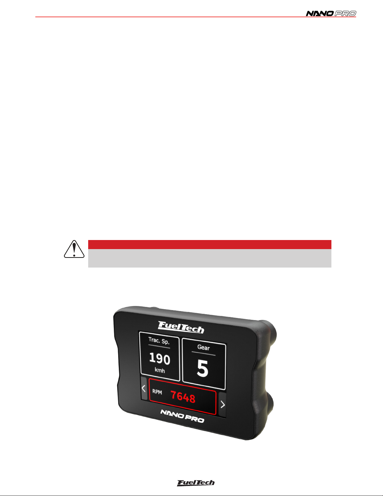
1. Presentation ................................................................................... 3
2. Warnings and warranty terms ............................................................ 4
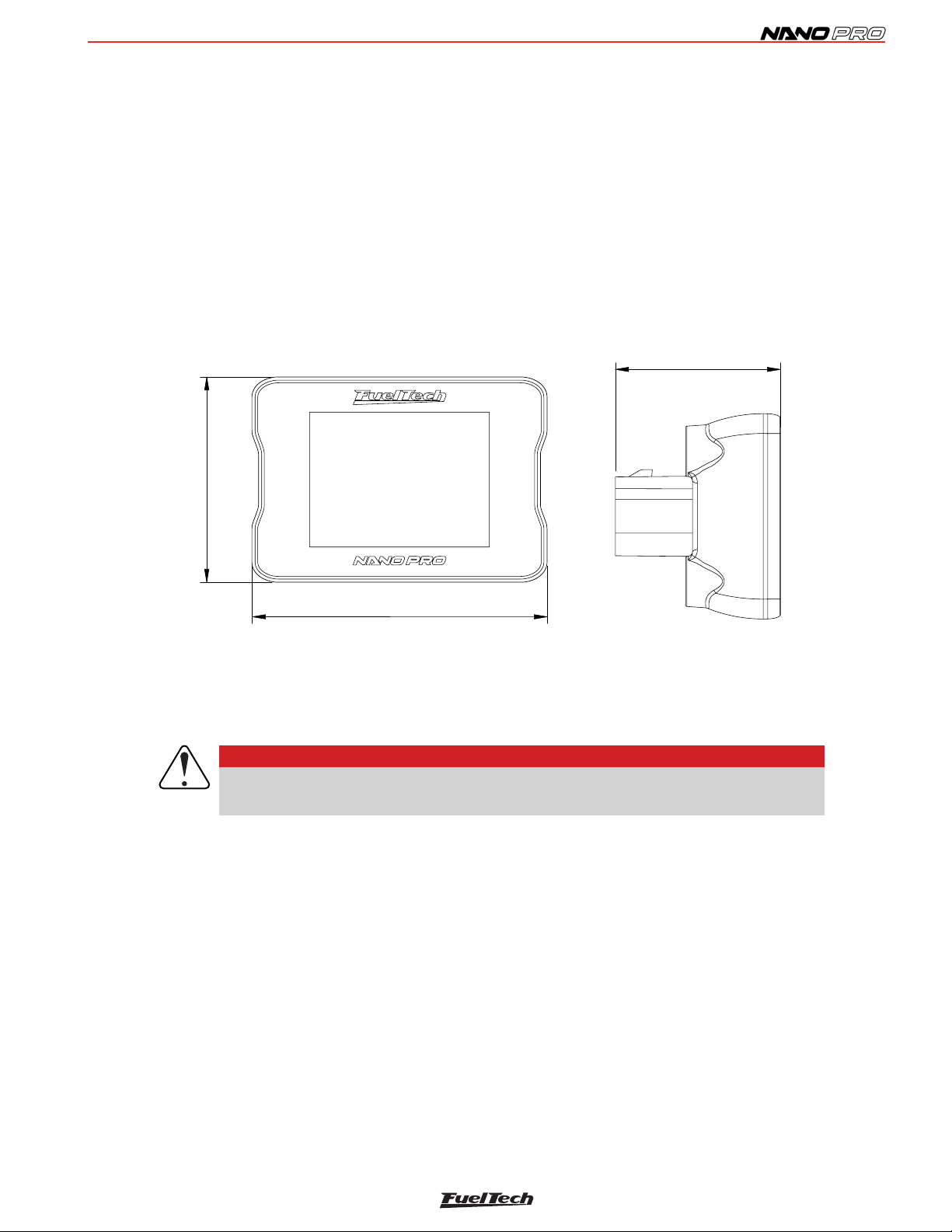
3. Characteristics ................................................................................ 5
3.1 Package contents...................................................................... 5
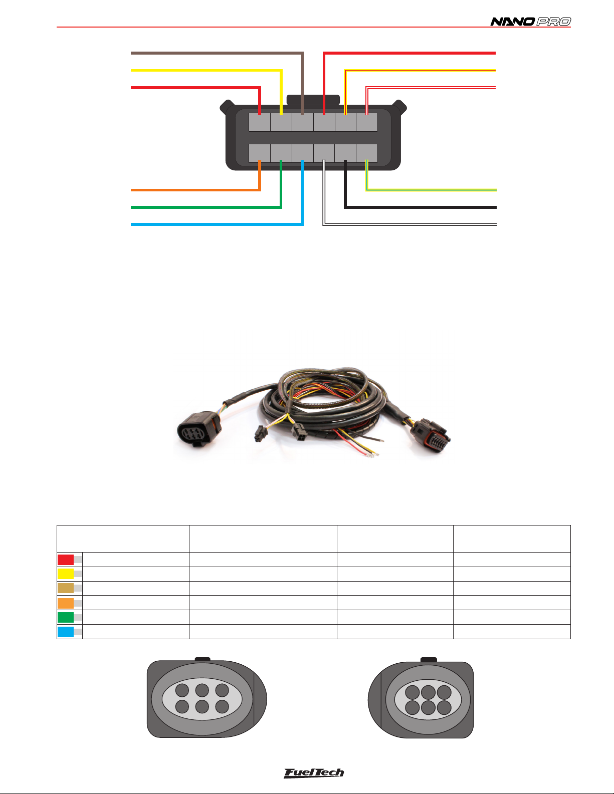
4. NanoPRO electrical installation........................................................... 6
4.1 Adapter harnesses..................................................................... 7
4.2 Replacement of Bosch LSU sensor connector 4.2 for 4.9............... 7
4.3 Replacement of Bosch LSU sensor connector 4.2 for 5.2............... 8
4.4 Replacement of Bosch LSU sensor connector 4.2 for NTK.............. 9
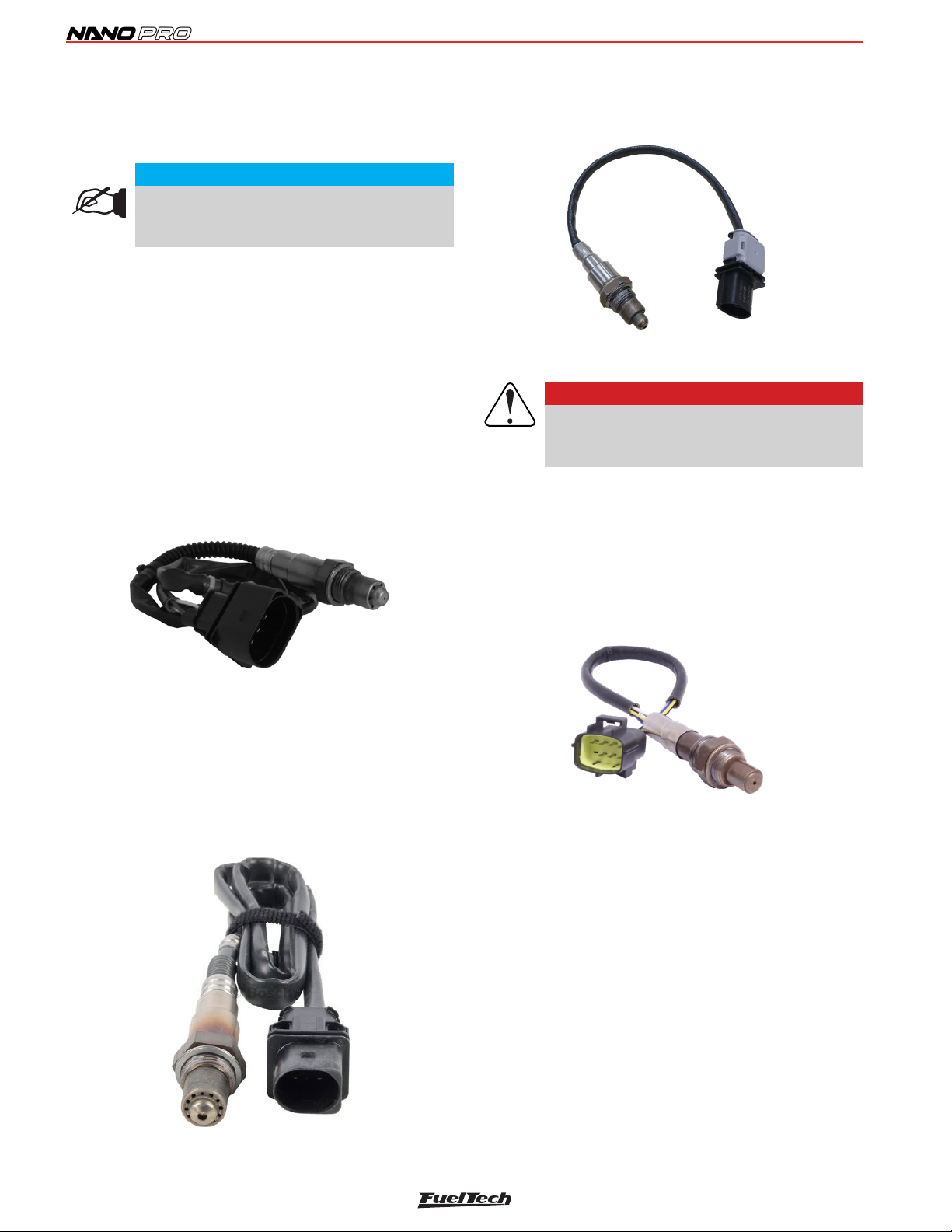
5. Wide band O2 sensor .................................................................... 10
5.1 Bosch LSU 4.2 O2 sensor ....................................................... 10
5.2 Bosch LSU 4.9 O2 sensor ....................................................... 10
5.3 Bosch LSU 5.2 O2 sensor ....................................................... 10
5.4 NTK O2 sensor ....................................................................... 10
5.5 O2 sensor installation............................................................... 11
5.6 O2 sensor for use in Diesel powered vehicles .............................. 11
6. OBD-II harness installation .............................................................. 12
6.1 Harness identication ............................................................... 12
6.2 OBD-II connector identication .................................................. 12
7. CAN communication ...................................................................... 13
7.1 FTCAN 2.0............................................................................. 13
7.2 FTCAN 1.0............................................................................. 13
8. Conguration through the NanoPRO interface .................................... 14
8.1 Dashboard conguration........................................................... 14
8.2 Display conguration................................................................ 15
8.3 Heating setup ......................................................................... 16
8.4 O2 sensor conguration ........................................................... 16
8.5 Manual .................................................................................. 17
8.6 Language............................................................................... 17
8.7 About .................................................................................... 17
87.8 Settings ............................................................................... 17
9. Conguration via the FTManager interface......................................... 19
9.1 Datalogger channels ................................................................ 20
9.2 NanoPRO software update........................................................ 21
10. Lambda readings analog outputs ..................................................... 22
10.1 Lambda analog output in Volts – 5.14 to 17.6 AFR ................... 22
10.2 Lambda analog output in Volts – 8.7 to 16.2 AFR (default) ......... 22
10.3 Lambda analog output in Volts – 9.6 to 19.1 AFR ..................... 22
10.4 Lambda analog output in Volts – 9.6 to 58.8 AFR ..................... 22
10.5 Lambda analog output in Volts – 9.6 to 146.9 AFR ................... 22
11. Analog output lambda/AFR ............................................................. 22
12. NanoPRO codes ........................................................................... 23
12.1 Informative codes.................................................................. 23
12.2 Error codes .......................................................................... 23
13. Fixing template (in) ........................................................................ 24

3
1. Presentation
FuelTech NanoPRO is a tool used for monitoring and datalog of air to fuel ratios on combustion engines. The device is able
to read and share with the ECU the following oxygen sensors: Bosch LSU 4.2 / Bosch LSU 4.9 / Bosch 5.2 and NTK
wide-band sensor.
Besides it’s multiple types of O2 sensors compatibility, the NanoPRO is also a dashboard, allowing the conguration of up to
5 screens to display information sent by the ECU (FTCAN 2.0), or work as button to activate various ECU functions.
FuelTech NanoPRO allows communicating with the FT300, FT350 and FT400 through the FTCAN 1.0 protocol, transforming
the NanoPRO into an auxiliary dashboard.
Monitor the engine’s air/fuel mixture and explore the complementary features, displaying complementary info or saving inputs
by activating buttons thought it’s screen.
The new NanoPRO is fully compatible with the WB-O2 NANO harness, sharing same connector and pinout.
When stand-alone, the display will only show the air/fuel mix information.
The NanoPRO provides the functionality to read original vehicle parameters through the OBD-II diagnostic port in original
vehicles. It is essential to note that this tool is only compatible with the ISO15765-CAN protocol and does not support other
protocols.
To use the NanoPRO with OBD-II, you will need to have the special harness, which includes the OBD connector and a wire
that must be connected to the vehicle’s ignition-switched power source.
Bosch sensors are self-calibrating, while NTK sensors require an air free calibration, see the manual for information about
the procedure.
IMPORTANT
After the Bosch LSU sensor is installed make sure you select the correct sensor. This will
prevent sensor damage and reading errors.
There are differences between AFR (air fuel ratio) from the Bosch LSU Sensor 4.2 and 4.9, so it’s necessary to correctly
congure the Bosch LSU Sensor type.

4
2. Warnings and warranty terms
The use of this equipment implies the total accordance with the terms described in this manual and exempts the manufacturer
from any responsibility regarding to product misuse.
Read all the information in this manual before starting the product installation.
This product must be installed and programmed by specialized auto shops and/or personnel with experience
on engine preparation and tuning.
Before starting any electrical installation, disconnect the battery.
The inobservance of any of the warnings or precautions described in this manual might cause engine damage and lead to
the invalidation of this product warranty. The improper adjustment of the product might cause engine damage.
This product does not have a certication for the use on aircrafts or any ying devices, as it has not been designed for such
use purpose.
In some countries where an annual inspection of vehicles is enforced, no modication in the original fuel injection system is
permitted. Be informed about local laws and regulations prior to the product installation.
Limited warranty
All products manufactured by FUELTECH are warranted to be free from defects in material and workmanship for one year
following the date of original purchase. Warranty claim must be made by original owner with proof of purchase from authorized
reseller.
This warranty does not include sensors or other products that FUELTECH carries but did not manufacture. If a product is found
defective, such products will, at FUELTECH’s option, be replaced or repaired at cost to FUELTECH. All products alleged by
Purchaser to be defective must be returned to FUELTECH, postage prepaid, within one year warranty period.
This limited warranty does not cover labor or other costs or expenses incidental to the repair and/or replacement of products
or parts.
This limited warranty does not apply to any product which has been subject to misuse, mishandling, misapplication, neglect
(including but not limited to improper maintenance), accident, improper installation, tampered seal, modication (including but
not limited to use of unauthorized parts or attachments), or adjustment or repair performed by anyone other than FUELTECH.
The parties hereto expressly agree that the purchaser’s sole and exclusive remedy against FUELTECH shall be for the repair
or replacement of the defective product as provided in this limited warranty. This exclusive remedy shall not be deemed to
have failed of its essential purpose so long as FUELTECH is willing and able to repair or replace defective goods.
FUELTECH reserves the right to request additional information such as, but not limited to, tune up and log les in order to
evaluate a claim.
Seal violation voids warranty and renders loss of access to upgrade releases.
Manual version 1.4 – February/2024

5
1.83 in
1.48 in
2.64 in
3. Characteristics
• Water proof (IP67 Certied)
• 2” display with resistive touchscreen
• Lambda readings shown on the display (2.94 to 146.9 AFR Gas)
• CAN communication with all ECU’s (FTCAN 1.0 and FTCAN 2.0)
• Analog output 0-5V
• Compatible with Bosch 4.2 / 4.9 / 5.2 O2-sensors and NTK sensor
• Congurable operating range
Lambda (0.21 - 9.99)
AFR Methanol (1.35 - 64.6)
AFR Gasoline (3.09 - 146.9)
AFR Ethanol (1.89 - 89.9)
• Dimensions: 2.64” x 1.83” x 1.48” (in)
IMPORTANT
Installation MUST use the screws that come with the product. Out of specication screws
may damage the housing, causing loss of warranty.
3.1 Package contents
• NanoPRO module
• Instructions manual
• 4 screws with washers (M4 x 6 PHILLIPS and M4 at washers)

6
4. NanoPRO electrical installation
The NanoPRO has a 12-way connector with 3 wire groups. One of them has the connector for the O2 sensor, the second
makes the CAN communication with PowerFT ECU’s and the third is responsible for power and analog output.
By default, the analog output is set to values of 8.7AFR to 16.2AFR Gas, but can be congured to 5.1AFR to 17.6AFR Gas
or 9.6AFR to 19.1AFR or 9.6AFR to 58.8AFR or yet 9.6AFR to 146AFR (Gas), if necessary.
See the following wiring diagram for details about connections.
Power Ground - Black/White
Lambda Output - Yellow/Red
Switched 12V - Red
Battery Ground - Black
7 8 9 10 11 12
1 2 3 4 5 6
O2 sensor - Pin 6 - Red
O2 sensor - Pin 5 - Yellow
O2 sensor - Pin 1 - Brown
CAN HI - Pin 4 - White/Red
O2 sensor - Pin 4 - Blue
O2 sensor - Pin 3 - Green
O2 sensor - Pin 2 - Orange
CAN LOW - Pin 3 - Yellow/Blue
Harness connector rear view
O2 Sensor LSU 4.2
IMPORTANT
NanoPRO has an accurate diagnosis that requires a good electrical installation, therefore,
it may be necessary to review and reinforce the harness, especially in the battery and
power grounds.
Wire color Pin Connection OBS to Connections
Red 1 O2 sensor O2 sensor - IP
Yellow 2 O2 sensor O2 sensor - sensor negative signal
Brown 3 O2 sensor O2 sensor - Sensor positive signal
Red 4 Switched 12V The use of a 10A fuse is recommended
Yellow/Red 5 0-5V Analog Output Analog output proportional to the lambda readings. Used for connection
with data acquisition systems
White/Red 6 CAN CAN (+): connected to PowerFT ECU’s CAN port
Orange 7 O2 sensor O2 sensor - sensor resistor calibration
Green 8 O2 sensor O2 sensor - sensor heater positive
Blue 9 O2 sensor O2 sensor - Sensor heater negative signal
Black/White 10 Chassis/Engine Power Ground Engine ground (head/block)
Do not connect it directly to the battery negative.
Black 11 Battery’s Negative Connected directly to the battery negative with no splices. Do not
connect this wire to the chassis engine block or head.
Yellow/Blue 12 CAN CAN (-): connected to PowerFT ECU’s CAN port
12-way connector

7
4.1 Adapter harnesses
The harness of the NanoPRO is the same as the WB-O2 NANO and is prepared for connection with a Bosch LSU 4.2 sensor.
To use other conditioners, it is necessary to purchase the specic harnesses for each one of them. It is also possible to buy
just the connector kits to replace the LSU 4.2 plug with another one.
5
26
31
4
Connector Bosch LSU 4.9
2
51
46
3
Connector Bosch LSU 4.2
4.2 Replacement of Bosch LSU sensor connector 4.2 for 4.9
This procedure is necessary if you want to use a Bosch LSU 4.9 sensor in a Bosch LSU 4.2 sensor harness. Refer to table
below for sensor pinout:
Harness connector rear view
Connector NanoPRO
(Wire color) - (pin) Function wire sensor Connector Bosch LSU
4.2 (Pin)
Connector Bosch LSU
4.9 (Pin)
1 - Red IP 6 1
2 - Yellow Ground sensor signal 5 2
3 - Brown Positive sensor signal 1 6
7 - Orange Calibration resistor sensor 2 5
8 - Green Heat positive signal sensor 3 4
9 - Blue Heat ground signal sensor 4 3
Power Ground - Black/White
Lambda Output - Yellow/Red
Switched 12V - Red
Battery Ground - Black
7 8 9 10 11 12
1 2 3 4 5 6
O2 sensor - Pin 1 - Red
O2 sensor - Pin 2 - Yellow
O2 sensor - Pin 6 - Brown
CAN HI - Pin 4 - White/Red
O2 sensor - Pin 3 - Blue
O2 sensor - Pin 4 - Green
O2 sensor - Pin 5 - Orange
CAN LOW - Pin 3 - Yellow/Blue
Harness connector rear view
O2 Sensor LSU 4.9

8
4.3 Replacement of Bosch LSU sensor connector 4.2 for 5.2
This procedure is necessary if you want to use a Bosch LSU 5.2 sensor in a Bosch LSU 4.2 Sensor harness. Refer to table
below for sensor pinout:
5
26
31
4
Connector Bosch LSU 5.2
2
51
46
3
Connector Bosch LSU 4.2
Harness connector rear view
O2 SENSOR - Pin 6 - Red
O2 SENSOR - Pin -2Yellow
O2 SENSOR Brown- Pin 1 -
O2 SENSOR - Pin 4 - Blue
O2 SENSOR - Pin 3 -Green
O2 SENSOR - Pin -5 Orange
Harness onnector rear viewc
2
51
4
3
6213456
7891011 12
O2 sensor
Bosch
LSU 4.9
Bosch LSU 4.9 electrical diagram
Connector NanoPRO
(Wire color) - (pin) Function wire sensor Connector Bosch LSU
4.2 (Pin)
Connector Bosch LSU
5.2 (Pin)
1 - Red IP 6 5
2 - Yellow Ground sensor signal 5 4
3 - Brown Positive sensor signal 1 1
7 - Orange Calibration resistor sensor 2 6
8 - Green Heat positive signal sensor 3 2
9 - Blue Heat ground signal sensor 4 3
IMPORTANT
The NanoPRO is factory congured to suit the Bosch LSU 4.2 sensor, if you want to
use another sensor, you need to change the conguration in the NanoPRO software.
This will prevent the sensor from being damaged or reading errors occurring.
WARNING
NEVER disconnect the O2-sensor with the NanoPRO powered, this could damage the
equipment.

9
2
51
46
3
Connector Bosch LSU 4.2
4.4 Replacement of Bosch LSU sensor connector 4.2 for NTK
This procedure is necessary if you want to use a NTK sensor in a Bosch LSU 4.2 Sensor harness. Refer to table below for
sensor pinout:
1
2
4
68
357
Connector NTK Sensor
Harness connector rear view
5
2
6
31
4
O2 SENSOR - Pin 6 - Red
O2 SENSOR - Pin 5 -Yellow
O2 SENSOR - Pin 1 -Brown
O2 SENSOR - Pin 4 - Blue
O2 SENSOR - Pin 3 -Green
O2 SENSOR - Pin 2 - Orange
Harness connector rear view
213456
7891011 12
O2 Sensor
Bosch
LSU 5.2
NTK Sensor electrical diagram
Bosch LSU 5.2 electrical diagram
1
2
4
68
357
O2 SENSOR Red- Pin 6 -
O2 SENSOR Yellow- Pin 5 -
O2 SENSOR Brown- Pin 1 -
O2 SENSOR 3Green- Pin -
Orange - Not Used
Harness connector rear view
213456
7891011 12
O2 sensor
-
NTK
O2 SENSOR Blue- Pin 4 -
Connector NanoPRO
(Wire color) - (pin) Function wire sensor Connector Bosch LSU
4.2 (Pin) Connector NTK Sensor
1 - Red IP 6 3
2 - Yellow Ground sensor signal 5 1
3 - Brown Positive sensor signal 1 5
7 - Orange Calibration resistor sensor 2 -
8 - Green Heat positive signal sensor 3 8
9 - Blue Heat ground signal sensor 4 6

10
5. Wide band O2 sensor
Better known as the oxygen sensor, it is responsible for reading the
exhaust air/fuel ratio. This sensor is essential for engine ne tuning.
Part number Bosch (Brazil): 0 258 007 057 or 0 258 007
351
VW: 021-906-262-B
5.2 Bosch LSU 4.9 O2 sensor
The Bosch LSU 4.9 O2 sensor works the same as the 4.2
5.3 Bosch LSU 5.2 O2 sensor
The O2 sensor Bosch LSU 5.2.
5.4 NTK O2 sensor
This O2 sensor is used in engine laboratories, due to its extreme
accuracy and speed in reading in different AFRs.
This O2 sensor requires an free-air calibration.
Free-air calibration
The NTK O2 sensor needs an open air calibration, so after conguring
in the software it is necessary to connect the sensor to the NanoPRO
and carry out the calibration.
To perform this procedure, rst connect the O2 sensor to the
NanoPRO and leave it out of the exhaust. Turn the ignition on, and
let the NTK O2 sensor heat up for 5 minutes, then access the sensor
setup menu, select NTK, and click on the “calibrate” button.
The calibration process is executed 5 times to guarantee the
expected result, after the test a message with the result will appear
on the screen. If an error message is displayed, it is necessary to
repeat the calibration procedure.
IMPORTANT
Bosch LSU oxygen sensors are not designed to
run on fuel that contains lead, and their lifespan
is drastically reduced to around 50 to 500 hours.
Part number Bosch (Brazil): 0 258 017 025
Part number Bosch (Brazil): 1 928 404 719
Part Number FuelTech: 5005100011
5.1 Bosch LSU 4.2 O2 sensor
Bosch LSU 4.2 sensor has an encased heating element and it is used
to measure the air fuel ratio, which determines the lambda value in
the remaining exhaust gas. Its signal indications vary from 5.14AFR
Gas (0,35λ)lambda (rich mixture) to open air lambda (innite).
The connector includes a calibration resistor (factory calibrated), which
denes the characteristics of the sensor and it is necessary for its
operation. It is with this resistor that the WB-O2 Nano automatically
calibrates the sensor.
NOTE
Running the engine with the sensor installed to the
exhaust and not connected to the NanoPRO (or other
conditioner) may damage the sensor.

11
5.5 O2 sensor installation
The sensor must be inserted in the exhaust system with its tip exposed to the exhaust gas ow. It must stay in an angle
between 10 to 80 degrees to horizontal position, that is, with its end downward, in such a way that steam droplets cannot
be accumulated between the body of the sensor and its ceramic part, which could cause damage when the sensor is used.
The sensor must not be placed vertically, as it becomes subject to excessive heat.
It is recommended that the sensor is installed at least one (1) meter away from the exhaust manifold to avoid excessive heat,
and at least one (1) meter away from the exhaust external output to avoid incorrect readings caused by oxygen in the air
outside the exhaust system.
Notice that such recommendations are not obligatory, as vehicles with a smaller exhaust system will need to have the sensor
placed closer to the engine.
The sensor must stay away from the cylinder head and from areas where one cylinder might affect the exhaust air more than
the others must. Avoid placing the sensor close to the exhaust manifold joints, as some allow the inow of air, resulting in
incorrect readings.
5.6 O2 sensor for use in Diesel powered vehicles
The NanoPRO allows readings of various fuels including engines fed with oil Diesel as fuel, in this case the recommended
O2 sensor are Bosch LSU 4.2 and 4.9.
For use in Diesel, it is necessary to take some precautions so as not to reduce the useful life of the probe, they are:
• AFR Diesel values between 11.60 and 15.95 are the maximum power for oil Diesel.
• It’s recommended to use AFR Diesel values upper than 18.85 where the exhaust gas temperature is lower.
• Black smoke is an indication of an extremely rich mixture and this particulate will drastically reduce the useful life of the
O2 sensor.

12
6. OBD-II harness installation
To use the NanoPRO as an OBD-II display, it is necessary to obtain the specic harness for this purpose.
6.1 Harness identication
1 - OBD-II connector
2 - NanoPRO connector
3 - 12V switched connector (T-Tap wire connector)
2
1
3
3
6.2 OBD-II connector identication
4 - Chassis ground
5 - Signal ground
6 - CAN HIGH
14 - CAN LOW
16 - 12V Battery
The other pins of the OBD-II port are not used by the NanoPRO.
IMPORTANT
NanoPRO is ONLY compatible with the ISO15765-CAN protocol.

13
7. CAN communication
7.1 FTCAN 2.0
The NanoPRO has CAN communication, which allows the module to send and read information from the PowerFT ECU’s
that are also connected in the network. Included on the Nano harness are two 4-way CAN connectors that plug and play
with other NanoPRO units as well as the PowerFT ECU’s.
When connected to the CAN port, the NanoPRO can read what the fuel and the measurement unit (lambda or AFR) that the
ECU is set, adjusting itself to these settings, disabling the analog output and sending the AFR value to ECU in the range of
2.94 to 149.9 AFR Gas.
In the CAN network, during the O2 sensor heating period, the value displayed in the PowerFT ECU’s will be equal to 0 (zero)
and the back of lambda gauge will turn yellow.
In case of any error during work, in addition to the warning on NanoPRO display, the error will be sent via CAN to the PowerFT
ECU’s and recorded in “Status Events” log.
To connect the NanoPRO via CAN to PowerFT ECU’s simply plug the 4-way cable to the ECU CAN port.
4
3
1234567 98
10 11 12 13 14 15 16 17
18 19 20 21 22 23 24 25
26 27 28 29 30 31 33 3432
Branco/Vermelho - CAN_A
Amarelo/Azul- CAN_A
4
3
WBO
2
NANO
4
3
Terminator
Connector B - FT600
FT250 / FT300 / FT350 / FT400
CAN Port
NanoPRO
Terminator
7.2 FTCAN 1.0
FuelTech NanoPRO also features FTCAN 1.0 communication, which allows you to receive information from the old line ECUs
such as FT250, FT300, FT350 and FT400.
To connect the NanoPRO to FT ECU from the old line, it is necessary to use the same communication port as the USB CAN
cable, that is, to use the NanoPRO, it is necessary to disconnect the USB CAN cable from the ECU.
The Lambda sensor reading will still be done by the analog output, being necessary to make the electrical connection of the
ECU with the NanoPRO through pin 5 (yellow/red wire).
The channels sent by the ECU to NanoPRO are as follows: RPM, map, engine temp, air temp, battery, fuel pressure, oil
pressure, tps, point, inj duty A and inj duty B.
IMPORTANT
When using the NanoPRO with an FT250 or FT300 you need to disable the Datalog function.

14
8. Conguration through the NanoPRO interface
It is possible to congure the FuelTech NanoPRO entirely from the screen. Below are a few example screens.
Single O2 sensor gauge O2 sensor with a data
eld Three data eld One button Two buttons
Single O2 sensor gauge
Using the interface
To navigate between screens, press the buttons (1) in the lower
corners of the interface.
There are two ways to get into the menu:
a - Press button (1) to change screens until you reach the menu
screen.
b - Press and hold the button (1) for one second to go directly to
the menu.
1 1
8.1 Dashboard conguration
Congures the number and information of the dashboards. It is
possible to create up to 5 different dashes.
Congure here the screen that will be the main dash, presented
on startup of the NanoPRO. You can choose the total number of
Dashboards, for that, click on one of the 3 free spaces.
Wideband meter
There are two possibilities for viewing the O2 sensor value.
Ideal range bar: In this option, the O2 sensor value will be shown on
the display and just below a bar with the ideal range of air/fuel mixture.
Gauge function for closed loop
The range is divided into 5 parts being numbered from left to right
from 1 to 5 and is adjusted according to the limits set in the closed
loop function.
1st: (red) value equal to the lower correction limit dened in the ECU
map.
2nd: (yellow) value less than the lower limit set in the ECU up to the
ideal minimum value O2 corr. set in the NanoPRO.
3rd: (green) value between the limits congured in the images above.
4th: (yellow) value upper than the ideal maximum value set in the
NanoPRO up to the upper limit of the correction in the ECU map.
5th: (red) Value equal to the upper limit of the correction dened in
the ECU map.
Wizard
The rst connect NanoPRO or then perform a factory reset, a menu
is displayed to choose the type of communication that the module
will execute.
a. Select the NanoPRO language.
b. Choose the type of communication that NanoPRO will works.
- FTCAN 1.0 and 2.0: for the module is connected via CAN
Network to a ECU FuelTech.
- OBDII: to use NanoPRO as an OBDII reader for stock cars.
- None: mode that disables CAN communication, NanoPRO
works only as a conditioner O2 sensor.
c. This conguration is used to choose the type of O2-sensor that
the NanoPRO works.
A B C

15
NOTE
To display a bigger O2 value on the display, do not
congure the ideal range values.
Value only: in this option the O2 sensor value will be very similar
to the WB-O2 Nano. Only the O2 sensor value will be displayed.
In this case, it is possible to congure the color of the value shown
on the display.
Available colors: white, blue, green, yellow, red and orange.
Select which will be the NanoPRO’s main dash screen. It’s possible
to congure any of ve screens as the main screen.
Data gauge
Select which data will be displayed in each dash. It is possible to
congure up to 3 parts of information per screen with different sizes
and positions.
If necessary, also congure the minimum and maximum values
for each congured information. These alerts are displayed on the
NanoPRO screen and are independent of the ECU, and may be
different values from those congured in each module.
Button
Select which buttons will be triggered in each dash. It is possible to
congure up to 2 buttons per screen.
After each conguration it is necessary to go to the last screen and
click on the save button.
NOTE
When the screen remains idling with no input from
the user for longer than 10 seconds, the action
is canceled and the interface returns to the main
screen.
IMPORTANT
Buttons to work correctly, it is necessary to
congure the inputs in the ECU map in the
FTManager software.
8.2 Display conguration
In this menu you can choose the screen lighting in day and night
modes. These values are independent of the ECU, that is, the day and
night values can be different between ECU and NanoPRO Switching
between modes can be activated by a button on the NanoPRO
screen or come directly from the ECU via the FTCAN 2.0 network.
After lighting setup, the display calibration screen will appear. It is
recommended that it be done on the rst installation and whenever
you notice difculty in touching the screen.

16
8.3 Heating setup
O2 sensor heating is essential for starting the lambda sensor reading.
On the NanoPRO there are 3 heating modes:
Normal: Standard heating currently used by the WB-O2 Nano.
This is the recommended mode for FuelTech ensuring a longer O2
sensor life.
It is possible to choose one of the three parameters to start the heating
in automatic mode (whenever it is turned on), by temperature or RPM.
Fast heating, uses a high current to shorten the heating time. By
using this option the O2 sensor life will be drastically reduced.
It is possible to choose one of the three parameters to start the heating
in automatic mode (whenever it is turned on), by temperature or RPM.
Limited: Limits heating current to 2, 2.5, and 3 Amps
It is possible to choose one of the three parameters to start the heating
in automatic mode (whenever it is turned on), by temperature or RPM.
8.4 O2 sensor conguration
Select the model of the O2 sensor installed in the car. On the next
screen congure the installation position.
The next step is to dene the unit, fuel type and also the working
scale (analog output).
Procedure for replacing the lambda O2-sensor
Perform the procedures described below to change the probe:
a - Disconnect the old O2 sensor and remove it.
b - Change the configuration for the new O2 sensor on the
NanoPRO.
c - Turn off the module.
d - Connect the new O2 sensor.
e - Turn on the NanoPRO.
Free-air calibration - NTK sensor
The NTK O2 sensor needs an open air calibration, so after conguring
in the software it is necessary to connect the sensor to the NanoPRO
and carry out the calibration.
To perform this procedure, rst connect the O2 sensor to the
NanoPRO and leave it out of the exhaust. Turn the ignition on, and
let the NTK O2 sensor heat up for 5 minutes, then access the sensor
setup menu, select NTK, and click on the “calibrate” button.
The calibration process is executed 5 times to guarantee the
expected result, after the test a message with the result will appear
on the screen. If an error message is displayed, it is necessary to
repeat the calibration procedure.
Possible errors after calibration - NTK sensor
Current highest 4.3 -> faulty sensor
Current below 3.2 -> sensor is not Free-air

17
Hour-meter - NTK sensor
This function allows checking the usage time of the probe installed
in the equipment. There is a RESET button to reset the usage time
count.
8.5 Manual
Through the interface there is a QR Code to download the manual
in its complete version with all the necessary information for the
operation of the NanoPRO.
8.6 Language
Fueltech NanoPRO has the possibility of changing language for the
interface.
8.7 About
This menu shows the O2 sensor usage time and the average heating
time, as well as the hardware, software and serial number of the
NanoPRO. It is also possible to reset the O2 sensor usage time by
clicking on the “Reset” button.
87.8 Settings
In this menu, the CAN communication mode is configured.
FTCAN 1.0: For old line ECUs (FT250, FT300, FT350 and FT400) this
conguration allows you to receive information from the following ECU
channels: RPM, map, engine temp, air temp, battery, fuel pressure,
oil pressure, tps, time , inj duty A and inj duty B.
To display this information, it is necessary to congure the gauges in
section “7.1 Panel conguration” on page 13.
It is also possible to congure a shift alert for FuelTech NanoPRO,
this alert is independent of the ECU.
IMPORTANT
When using the NanoPRO with an FT250 or
FT300 the datalog function is automatically
disabled.
To disable the internal Datalogger follow the steps in the image below.
1 - Click the down button until you locate the internal Datalogger
menu.
2 - Click the button to the right.
3 - Click the down button until the “Internal Log disabled”
information appears.
FTCAN 2.0: This protocol allows communicating with the PowerFT
line modules (FT450, FT500, FT550 and FT600), with this
conguration it is possible to congure buttons to ECU functions on/
off, read EGT sensors,the RPM shift light and Alerts synchronized
with the ECU.
ECU Alerts: These warnings are activated when the condition
congured in the ECU is reached, and will remain active until the
user touches the screen. They will reappear after 10 seconds if the
condition congured in the ECU still persists.
Recording Mode
Continuous
Recording Mode
Single
Internal Log
Enabled
Internal Log
Disabled
Internal
Datalogger
Log Start
RPM Signal
Log Start
Two-Step Button
Start Log Above Sample Rate
20Hz (2.5min)
Sample Rate
Sample Rate
Sample Rate
2000rpm
10Hz (5min)
5Hz (10min)
2Hz (25min)

18
OBD-II: This protocol allows to read the parameters of original cars
through the OBD-II connector with CAN protocol. For the correct
display of the parameters in the NanoPRO it is necessary to congure
the measurement units such as temperature, pressure, speed, and
consumption.
After this conguration is necessary to congure the screens with
the parameters to be displayed, for this see the item "8.1 Panel
Conguration".
List of NanoPRO OBD-II compatible cars
Below is a list of cars already tested and that are compatible with
CAN reading through OBD-II.
Brand Car Year
BMW
530i 2021
328i 2015
VW
Fox 2013
Saveiro 2016
Virtus 2023
Jetta 2008
Chevrolet
Prisma 2019
Spin 2021
Renault Symbol -
Jeep Compass -
NanoPRO is only compatible with ISO15765-CAN protocol, some
vehicles use another protocol and with that the NanoPRO will not
work. Consult technical support to nd out what the standard protocol
of your vehicle is.
List of cars INCOMPATIBLE with NanoPRO OBD-II
Below is a list of already tested cars that are NOT compatible with
NanoPRO.
Brand Car Year
Fiat
Siena 2011
Doblo 2013
Punto T-Jet 2016
Chevrolet Blazer 2006
Honda Fit 2008
Information available on OBD-II for reading
The channels that are available for reading through OBD-II are:
- Load engine
- Engine Temperature
- Fuel short term correction
- Fuel long term Correction
- Fuel pressure
- MAP
- RPM
- Speed
- Advance of Ignition
- Air Temperature
- TPS
- Oil temperature
- Fuel differential pressure
- Fuel differential pressure gauge
- O2 Sensor Bank 1 Sensor 1
- O2 Sensor Bank 1 Sensor 2
- O2 Sensor Bank 2 Sensor 1
- O2 Sensor Bank 2 Sensor 2
- Barometric pressure
- Ethanol %
- Fuel differential pressure absolute
- Injection time
- Fuel ow
- Gear
- Lambda
- Sensor O2 Narrow band Voltage
There will be cases where the channel will be available in NanoPRO
but the vehicle does not have this information in the CAN, in this case
the gauge will be with (----) and may be replaced by other information
that it deems relevant.
FORD
Ka 2013 a 2016
Focus 2009
Fiesta 1.6 2014
Peugeout 208 GT THP 2017

19
9. Conguration via the FTManager interface
To congure the NanoPRO through the FTManager software, follow the steps described below:
a - Open the map in FTManager software
b - Access the “Tools” menu and then click on “External Modules” and locate NanoPRO and open the conguration screen.
This screen is divided into four distinct parts.
1 - Dashboard conguration: Allows you to congure the 5 dashboard screens with the data you deem necessary, as well
as dene which will be the main screen.
2 - Advanced Settings: There are three tabs with all the necessary settings for the NanoPRO to operate correctly
- Display and language: select the language of the NanoPRO and set the brightness levels for day and night mode.
- Heating: adjusts the O2 sensor heating mode and sets the parameters of RPM and minimum temperature for the
start of heating.
- O2 sensor: denes which sensor will be used, Unit of measure and the Range of the analog output.
- CAN Network: congures the network protocol used, FTCAN 1.0 or 2.0, as well as triggering alerts and shift light.
- Units: Congures the units for temperature, pressure, speed, consumption and ow.
3 - Buttons and NanoPRO selection: there are four buttons for reading and writing the settings in the NanoPRO memory
as well as selecting which device is being congured (if you have more than one NanoPRO on the CAN network).
4 - Serial number and hardware and rmware version.
1 3
42

20
Conguration to use NanoPRO out of the CAN network
NanoPRO allows the selection of the display unit and O2 sensor reading scale, but, these settings are read from the PowerFT
ECU’s during its initialization. In case it is removed from the CAN network, NanoPRO goes back to factory conguration.
9.1 Datalogger channels
There are 3 log channels for each O2 sensor tted to the vehicle, which record information about the O2 sensor heating.
With these channels it is possible to have a complete diagnosis, letting you know if the sensor is installed in the correct
position, for example.
Sensor heater PWM: Records the percentage of duty cycle applied to the O2 sensor heater
Sensor temperature: Records the internal temperature of the sensor
Sensor resistance: Records the internal resistance in Ohms of the sensor
Other manuals for Nano PRO
1
Table of contents
Other FuelTech Automobile Accessories manuals

FuelTech
FuelTech FTSPARK User manual

FuelTech
FuelTech Seadoo Rotax 300 2010-2023 User manual

FuelTech
FuelTech FTINJECTOR User manual

FuelTech
FuelTech 9588 User manual

FuelTech
FuelTech SparkPro Operating instructions

FuelTech
FuelTech FTSPARK 750mJ User manual

FuelTech
FuelTech 5218 User manual

FuelTech
FuelTech EGT-8 CAN User manual

FuelTech
FuelTech FT500 LITE User manual

FuelTech
FuelTech FT450 User manual