2WWW.FUHR.DE
836
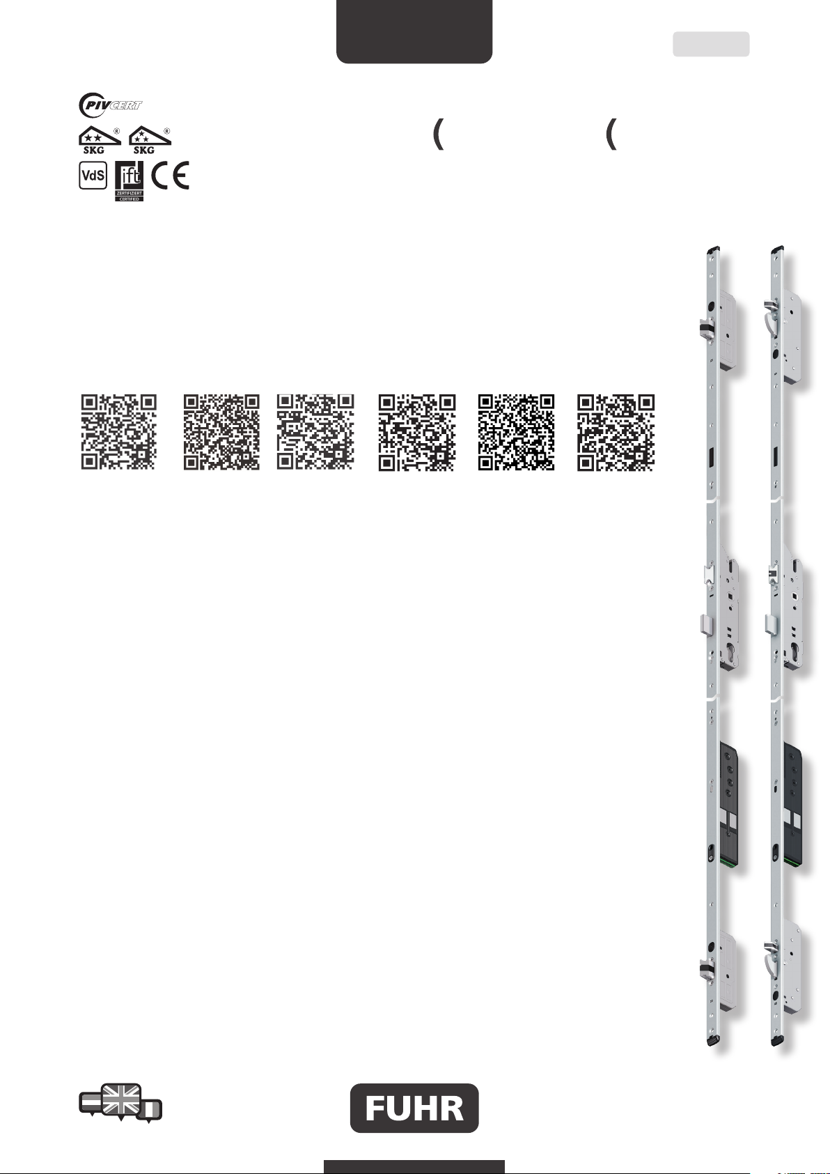
autotronic
834
autotronic
1 Wichtige Hinweise
Important notes
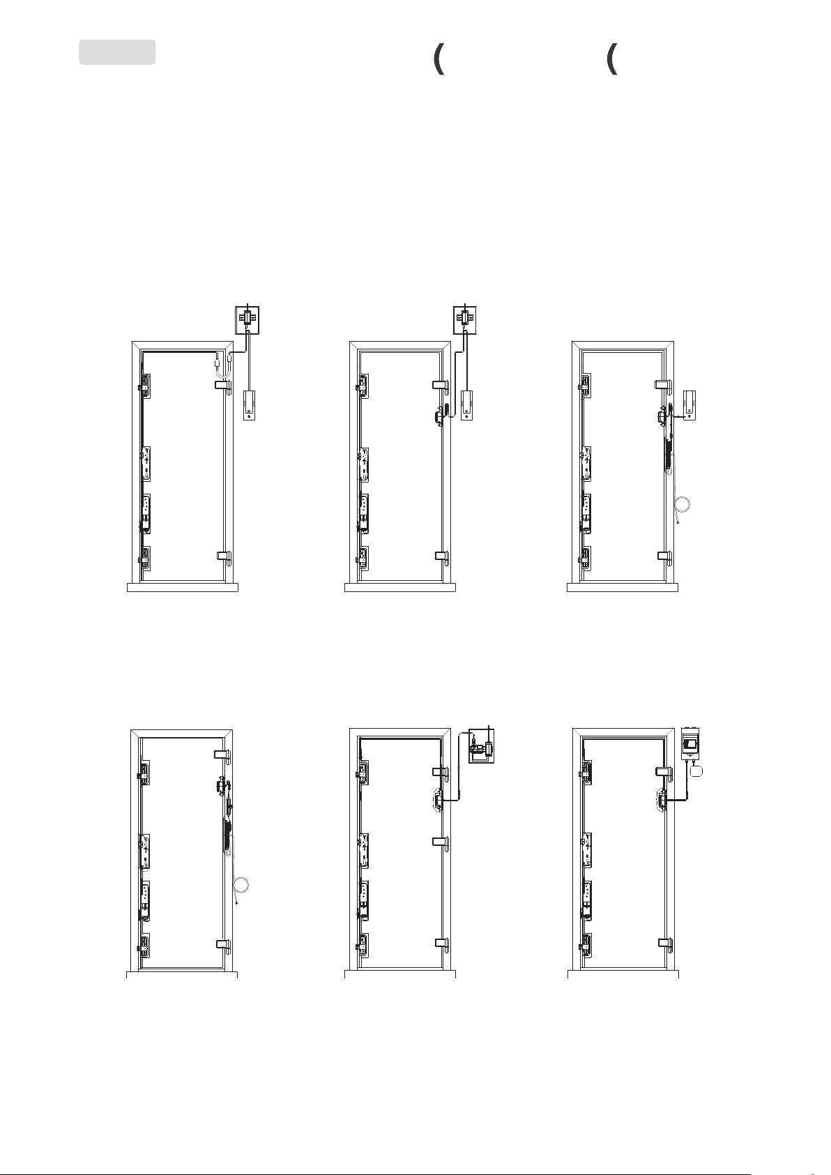
Die Mehrfachverriegelung FUHR autotronic 834/836 ist
für den Einbau in Haus-, Wohnungs-, Objekt- und Neben-
eingangstüren vorgesehen.
Die Mehrfachverriegelung FUHR autotronic 834/836 ist
konstruktiv auf die Verwendung der FUHR autotronic-
Komponenten ausgelegt. Bei unsachgemäß durchgeführter
Montage des Systems und/oder bei Verwendung von nicht
originalen bzw. nicht werkseitig freigegebenen System-
zubehörteilen wird keine Haftung übernommen. Die Ver-
änderung von Bauteilen oder die Verwendung von nicht
zugelassenen Zubehörteilen können Störungen hervorrufen.
Bei Sach- oder Personenschäden, die durch Nichtbeachtung
der Montage- und Bedienungs- und Wartungsanleitung
oder unsachgemäße Handhabung entstehen, erlischt die
Gewährleistung. Für Folgeschäden, die daraus resultieren,
übernehmen wir keine Gewährleistung.
Die Mehrfachverriegelung FUHR autotronic 834/836 ist vor
Feuchtigkeit zu schützen. Sie ist nicht geeignet für Bereiche mit
hoher Luftfeuchtigkeit und/oder chemischen Substanzen.
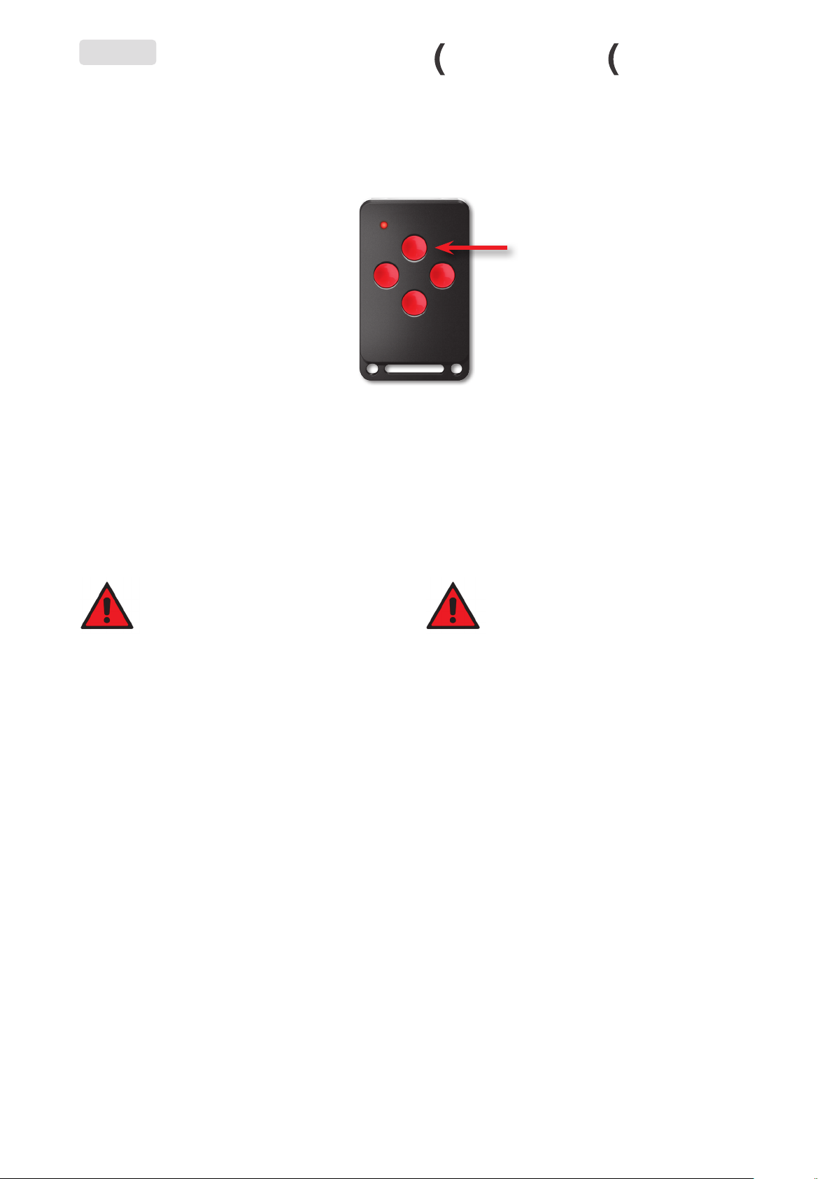
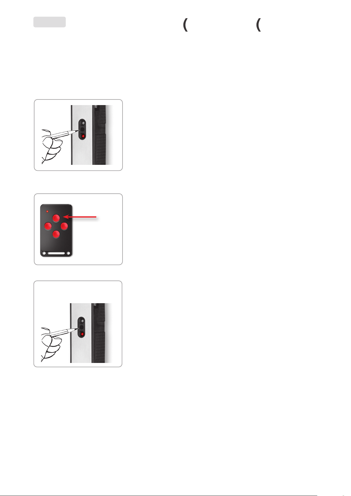
Wichtig!
Um auch bei Notfällen (z. B. Stromausfall)
jederzeit den Zutritt sicherzustellen, sollte
stets ein Schlüssel des Zylinders mitgeführt
werden.
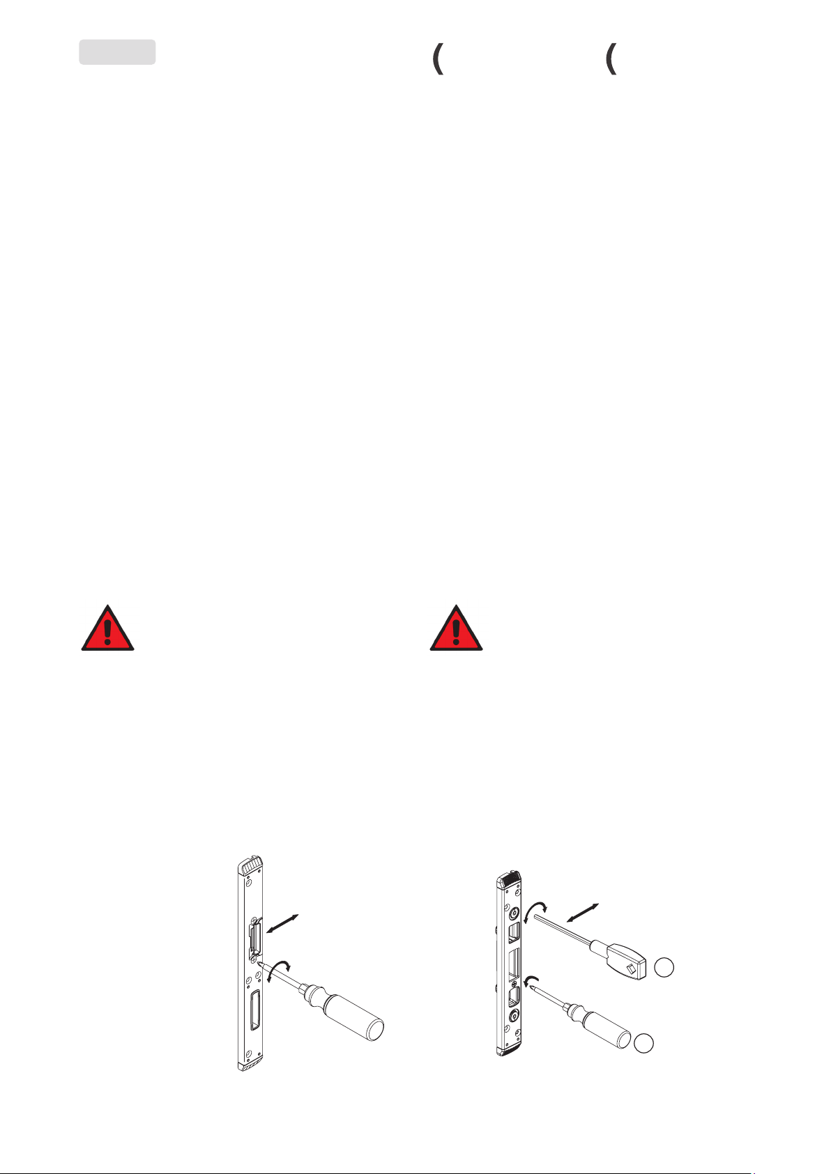
Einstellungsmöglichkeiten
Eine zuverlässige Funktion des Türsystems ist nur dann ge-
währleistet, wenn Schloss und Tür korrekt eingebaut sowie
Bänder und Schließteile korrekt eingestellt wurden. Um die
Dichtigkeit der Tür optimal einzustellen, können die Schließ-
teile/Schließleisten wie folgt verstellt werden:
The FUHR autotronic 834/836 multipoint locking system
has been designed for installation in main entrance doors,
apartment doors, doors of public buidlings and back doors.
The FUHR autotronic834/836 multipoint locking system has
been engineered to be used in conjunction with the provided
FUHR autotronic components. We accept no liability for
improperly installed systems and/or the use of non-original
or non factory approved system accessory parts. The modifi-
cation of components or the use of non approved accessory
components can cause malfunctions. Material damage or
personal injury resulting from non-compliance with the
installation, operation and maintenance instructions or
inappropriate operation invalidates the warranty. We assume
no liability for any consequential damage.
The FUHR autotronic 834/836 multipoint locking system
must be protected from humidity. It is not suitable for areas
with high humidity and/or chemical substances.
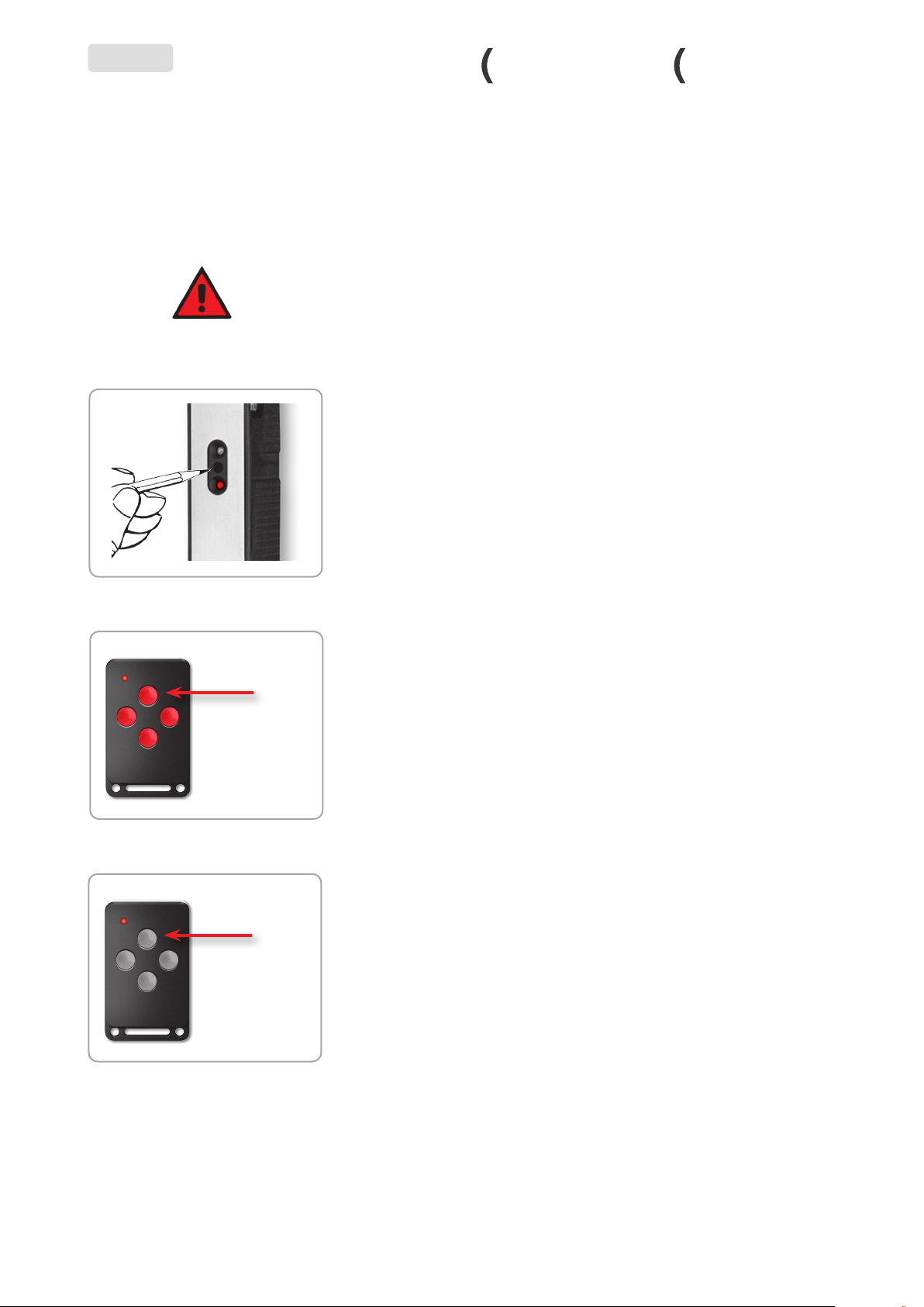
Important!
In order to ensure that the door can be
opened in the event of an emergency (e.g.
power failure), the cylinder key should
always be carried in addition to the radio key.
Adjustment options
Reliable function of the door system is only guaranteed if
the lock and door are installed correctly and the hinges and
strike plates have been adjusted correctly. In order to opti-
mally adjust the tightness of the door, the standard or one-
piece strike plates can be adjusted as follows:
DE | EN
± 2mm
90°
SW 4
2.
1.
± 2mm