English
- 5 -
Determining the Top Line Location of the
Rear Wall Template under Your Cabinet
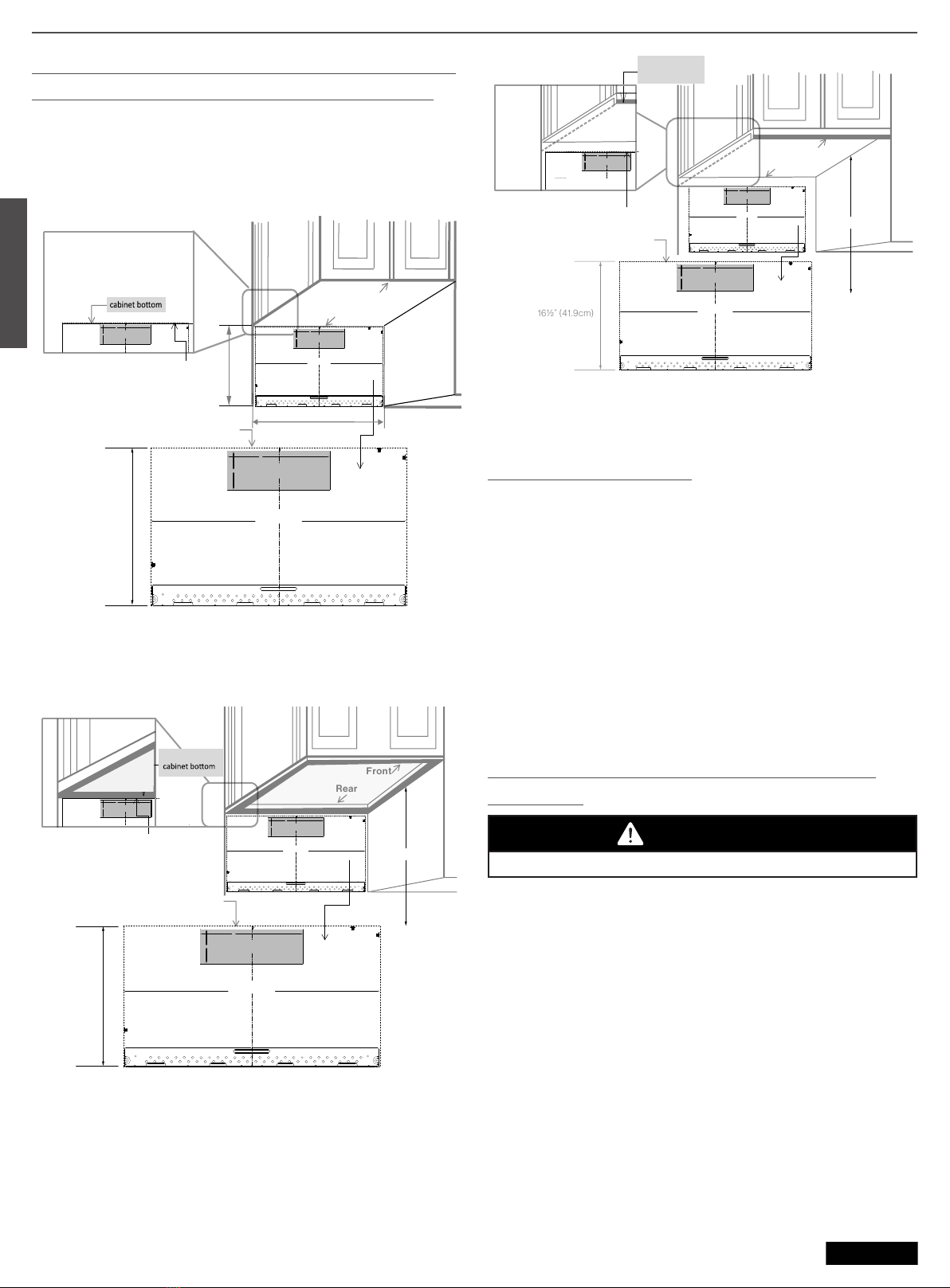
Mounting Plate - Beneath flat bottom cabinet:
Draw a vertical line on the wall at the center of the 30"
(76.2cm) wide space. Tape the Rear Wall Template onto the
wall matching the centerline. The TOP LINE OF REAR WALL
TEMPLATE must align with cabinet bottom.
Front
Rear
Min. 30” (76.2cm)
TOP LINE OF REAR WALL TEMPATE
TOP LINE OF REAR WALL TEMPATE
16½” (41.9cm)
16½” (41.9cm)
3/8"TO EDGE
CAUTION- IF EXHAUSTADAPTOR IS POSITIONED OUTSIDE
RECOMMENDEDDIMENSION, GREASE-LADEN AIR WILL
DISCHARGEINTO HOUSE STRUCTURE.
30" MINIMUM WIDTH REQUIRED
REAR WALL TEMPLATE
NOTE:IT IS VERY IMPORTANTTO
READAND FOLLOW THE DIRECTIONS
INTHE INSTALLATIONINSTRUCTIONS
BEFOREPROCEEDING WITH THIS
REARWALL TEMPLATE.
ThisRear Wall Templateserves to position the bottom
mountingplate and to locate the horizontalexhaust
outlet.
1.Use a level to check that the template is positioned
accurately.
2.Locate and mark at least one stud on the leftor
rightside of the centerline.
NOTE:
Itis important to use at least one wood
screw mounted firmly in a stud to support the weight
ofthe microwave.Mark two additional, evenly spaced
locationsfor the supplied toggle bolts.
3.Drill holes in the marked locations. Where thereis
astud, drill a 3/16" hole for wood screws.For holes
thatdo not line up with a stud, drill 5/8"holes for
togglebolts.
NOTE:
DONOT INSTALLTHE MOUNTING PLATE
ATTHISTIME.
4.Remove the template fromthe rear wall.
5.Review the Installation Instruction book foryour
installationsituation.
Locateand mark holes to align with holes in the
mountingplate.
IMPORTANT:
LOCATEATLEASTONE STUD ON EITHER SIDE OF
THECENTERLINE.
MARKTHE LOCATIONFOR 2 ADDITIONAL, EVENLY
SPACEDTOGGLEBOLTS IN THE MOUNTING PLATE
AREA.
Locateand mark holes to align with holes in the
mountingplate.
IMPORTANT:
LOCATEATLEASTONE STUD ON EITHER SIDE OF
THECENTERLINE.
MARKTHE LOCATIONFOR 2 ADDITIONAL, EVENLY
SPACEDTOGGLEBOLTS IN THE MOUNTING PLATE
AREA.
Trimthe rear wall templatealong the dotted line.
Trimthe rear wall templatealong the dotted line.
C
AB C
D
F.CUT OUT FOR HORIZONTAL
OUTSIDE EXHAUST
CUTHOLE THROUGH REAR WALL FOREXHAUST ADAPTOR
12"
4"
Darlevuelta a la hoja para consultar la
versiónen Español.
3/8"TOEDGE
CAUTION-IFEXHAUST ADAPTORIS POSITIONED OUTSIDE
RECOMMENDED DIMENSION, GREASE-LADEN AIR WILL
DISCHARGEINTOHOUSESTRUCTURE.
30"MINIMUM WIDTH REQUIRED
REAR WALL TEMPLATE
NOTE:ITIS VERY IMPORTANTTO
READANDFOLLOWTHE DIRECTIONS
INTHEINSTALLATIONINSTRUCTIONS
BEFOREPROCEEDINGWITH THIS
REARWALLTEMPLATE.
ThisRearWallTemplateserves to position the bottom
mountingplateandto locate the horizontal exhaust
outlet.
1.Usealevel to check that the template is positioned
accurately.
2.Locateandmark at least one stud on the left or
right side of the centerline.
NOTE:
Itisimportantto use at least one wood
screw mounted firmly in a stud to support the weight
ofthemicrowave.Mark two additional, evenly spaced
locationsforthesupplied toggle bolts.
3.Drillholesin the marked locations. Where there is
a stud, drill a 3/16" hole for wood screws. Forholes
that do not line up with a stud, drill 5/8" holes for
toggle bolts.
NOTE:
DONOTINSTALLTHEMOUNTING PLATE
ATTHISTIME.
4.Removethetemplate from the rear wall.
5.ReviewtheInstallation Instruction book for your
installation situation.
Locateandmark holes to align with holes in the
mountingplate.
IMPORTANT:
LOCATEATLEASTONESTUD ON EITHER SIDE OF
THECENTERLINE.
MARKTHELOCATIONFOR 2 ADDITIONAL, EVENLY
SPACEDTOGGLEBOLTSINTHE MOUNTING PLATE
AREA.
Locateandmark holes to align with holes in the
mountingplate.
IMPORTANT:
LOCATEATLEASTONESTUD ON EITHER SIDE OF
THECENTERLINE.
MARKTHELOCATIONFOR 2 ADDITIONAL, EVENLY
SPACEDTOGGLEBOLTSINTHE MOUNTING PLATE
AREA.
Trimtherearwall template along the dotted line.
Trimtherearwall template along the dotted line.
C
AB C
D
F.CUT OUT FOR HORIZONTAL
OUTSIDE EXHAUST
CUTHOLETHROUGHREAR WALL FOR EXHAUST ADAPTOR
12"
4"
Darlevueltaa la hoja para consultar la
versiónenEspañol.
3/8"TOEDGE
CAUTION-IFEXHAUST ADAPTORIS POSITIONED OUTSIDE
RECOMMENDED DIMENSION, GREASE-LADEN AIR WILL
DISCHARGEINTOHOUSESTRUCTURE.
30"MINIMUM WIDTH REQUIRED
REAR WALL TEMPLATE
NOTE:ITIS VERY IMPORTANTTO
READANDFOLLOWTHE DIRECTIONS
INTHEINSTALLATIONINSTRUCTIONS
BEFOREPROCEEDINGWITH THIS
REARWALLTEMPLATE.
ThisRearWallTemplateserves to position the bottom
mountingplateandto locate the horizontal exhaust
outlet.
1.Usealevel to check that the template is positioned
accurately.
2.Locateandmark at least one stud on the left or
right side of the centerline.
NOTE:
Itisimportantto use at least one wood
screw mounted firmly in a stud to support the weight
ofthemicrowave.Mark two additional, evenly spaced
locationsforthesupplied toggle bolts.
3.Drillholesin the marked locations. Where there is
a stud, drill a 3/16" hole for wood screws. Forholes
that do not line up with a stud, drill 5/8" holes for
toggle bolts.
NOTE:
DONOTINSTALLTHEMOUNTING PLATE
ATTHISTIME.
4.Removethetemplate from the rear wall.
5.ReviewtheInstallation Instruction book for your
installation situation.
Locateandmark holes to align with holes in the
mountingplate.
IMPORTANT:
LOCATEATLEASTONESTUD ON EITHER SIDE OF
THECENTERLINE.
MARKTHELOCATIONFOR 2 ADDITIONAL, EVENLY
SPACEDTOGGLEBOLTSINTHE MOUNTING PLATE
AREA.
Locateandmark holes to align with holes in the
mountingplate.
IMPORTANT:
LOCATEATLEASTONESTUD ON EITHER SIDE OF
THECENTERLINE.
MARKTHELOCATIONFOR 2 ADDITIONAL, EVENLY
SPACEDTOGGLEBOLTSINTHE MOUNTING PLATE
AREA.
Trimtherearwall template along the dotted line.
Trimtherearwall template along the dotted line.
F.CUT OUT FOR HORIZONTAL
OUTSIDE EXHAUST
CUTHOLETHROUGHREAR WALL FOR EXHAUST ADAPTOR
12"
4"
Darlevueltaa la hoja para consultar la
versiónenEspañol.
Mounting Plate - Beneath framed recessed cabinet:
Draw a vertical line on the wall at the center of the 30" (76.2cm)
space. Tape the Rear Wall Template onto the wall matching the
centerline. The TOP LINE OF REAR WALL TEMPLATE must
align with the back frame of cabinet bottom.
3/8"TOEDGE
CAUTION-IF EXHAUST ADAPTOR IS POSITIONED OUTSIDE
RECOMMENDED DIMENSION, GREASE-LADEN AIR WILL
DISCHARGEINTO HOUSE STRUCTURE.
30" MINIMUM WIDTHREQUIRED
REAR WALL TEMPLATE
NOTE:IT IS VERY IMPORTANTTO
READAND FOLLOW THE DIRECTIONS
INTHE INSTALLATIONINSTRUCTIONS
BEFOREPROCEEDING WITH THIS
REARWALL TEMPLATE.
ThisRear WallTemplate serves toposition the bottom
mountingplate and to locatethe horizontal exhaust
outlet.
1.Use a level to check that the templateis positioned
accurately.
2.Locate and mark atleast one stud on the left or
right side of the centerline.
NOTE:It is important to use at least one wood
screw mounted firmly in a stud to support the weight
ofthe microwave.Mark two additional, evenly spaced
locationsfor the supplied toggle bolts.
3.Drill holes in the marked locations. Wherethere is
a stud, drill a 3/16" hole for wood screws. Forholes
that do not line up with a stud, drill 5/8" holes for
toggle bolts.
NOTE:DO NOT INSTALLTHE MOUNTING PLATE
ATTHISTIME.
4.Remove the templatefrom the rear wall.
5.Review the InstallationInstruction book for your
installation situation.
Locateand mark holes to align with holes in the
mountingplate.
IMPORTANT:
LOCATEATLEASTONE STUD ON EITHER SIDE OF
THECENTERLINE.
MARKTHE LOCATIONFOR 2 ADDITIONAL, EVENLY
SPACEDTOGGLEBOLTS IN THE MOUNTING PLATE
AREA.
Locateand mark holes to align with holes in the
mountingplate.
IMPORTANT:
LOCATEATLEASTONE STUD ON EITHER SIDE OF
THECENTERLINE.
MARKTHE LOCATIONFOR 2 ADDITIONAL, EVENLY
SPACEDTOGGLEBOLTS IN THE MOUNTING PLATE
AREA.
Trimthe rear walltemplate along the dotted line.
Trimthe rear walltemplate along the dotted line.
C
AB C
D
F.CUT OUT FOR HORIZONTAL
OUTSIDE EXHAUST
CUTHOLE THROUGH REAR WALLFOR EXHAUST ADAPTOR
12"
4"
Darlevuelta a la hoja para consultar la
versiónen Español.
3/8"TOEDGE
CAUTION-IFEXHAUST ADAPTORIS POSITIONED OUTSIDE
RECOMMENDED DIMENSION, GREASE-LADEN AIR WILL
DISCHARGE INTO HOUSE STRUCTURE.
30"MINIMUM WIDTH REQUIRED
REAR WALL TEMPLATE
NOTE:ITIS VERYIMP ORTANTTO
READANDFOLLOWTHE DIRECTIONS
INTHEINSTALLATIONINSTRUCTIONS
BEFOREPROCEEDINGWITH THIS
REARWALLTEMPLATE.
ThisRearWallTemplateserves to position the bottom
mountingplateandto locate the horizontal exhaust
outlet.
1.Usealevel to check that the template is positioned
accurately.
2.Locateandmark at least one stud on the left or
right side of the centerline.
NOTE:Itis important to use at least one wood
screw mounted firmly in a stud to support the weight
ofthemicrowave.Mark two additional, evenly spaced
locationsforthesupplied toggle bolts.
3.Drillholesin the marked locations. Where there is
a stud, drill a 3/16" hole for wood screws. Forholes
that do not line up with a stud, drill 5/8" holes for
toggle bolts.
NOTE:DONOT INSTALLTHE MOUNTING PLATE
ATTHISTIME.
4.Removethetemplate from the rear wall.
5.ReviewtheInstallation Instruction book for your
installation situation.
Locateandmark holes to align with holes in the
mountingplate.
IMPORTANT:
LOCATEATLEASTONESTUD ON EITHER SIDE OF
THECENTERLINE.
MARKTHELOCATIONFOR 2 ADDITIONAL, EVENLY
SPACEDTOGGLEBOLTSINTHE MOUNTING PLATE
AREA.
Locateandmark holes to align with holes in the
mountingplate.
IMPORTANT:
LOCATEATLEASTONESTUD ON EITHER SIDE OF
THECENTERLINE.
MARKTHELOCATIONFOR 2 ADDITIONAL, EVENLY
SPACEDTOGGLEBOLTSINTHE MOUNTING PLATE
AREA.
Trimtherearwall template along the dotted line.
Trimtherearwall template along the dotted line.
C
AB C
D
F.CUT OUT FOR HORIZONTAL
OUTSIDEEXHAUST
CUTHOLETHROUGHREAR WALL FOR EXHAUSTADAPTOR
12"
4"
Darlevueltaa la hoja para consultar la
versiónenEspañol.
3/8"TOEDGE
CAUTION-IFEXHAUSTADAPTOR IS POSITIONED OUTSIDE
RECOMMENDED DIMENSION, GREASE-LADEN AIR WILL
DISCHARGEINTOHOU SE STRUCTURE.
30"MINIMUM WIDTH REQUIRED
REAR WALLTEMPL ATE
NOTE:ITISVERY IMPORTANT TO
READANDFOLLOWTHE DIRECTIONS
INTHEINSTALLATIONINSTRUCTIONS
BEFOREPROCEEDINGWITHTHIS
REARWALLTEMPLATE.
ThisRearWallTemplateserves to position the bottom
mountingplateandto locate the horizontalexhaust
outlet.
1.Usealevel to check that the template is positioned
accurately.
2.Locateandmark at least one stud on the leftor
right side of the centerline.
NOTE:
Itisimportantto use at least one wood
screw mounted firmly in a stud to support the weight
ofthemicrowave.Marktwo additional, evenly spaced
locationsforthesupplied toggle bolts.
3.Drillholesin the marked locations. Where thereis
a stud, drill a 3/16" hole for wood screws.For holes
that do not line up with a stud, drill 5/8"holes for
toggle bolts.
NOTE:
DONOTINSTALLTHEMOUNTING PLATE
ATTHISTIME.
4.Removethetemplate fromthe rear wall.
5.ReviewtheInstallation Instruction book foryour
installation situation.
Locateandmarkholes to align with holes in the
mountingplate.
IMPORTANT:
LOCATEATLEASTONESTUD ON EITHER SIDE OF
THECENTERLINE.
MARKTHELOCATIONFOR 2 ADDITIONAL, EVENLY
SPACEDTOGGLEBOLTSINTHE MOUNTING PLATE
AREA.
Locateandmarkholes to align with holes in the
mountingplate.
IMPORTANT:
LOCATEATLEASTONESTUD ON EITHER SIDE OF
THECENTERLINE.
MARKTHELOCATIONFOR 2 ADDITIONAL, EVENLY
SPACEDTOGGLEBOLTSINTHE MOUNTING PLATE
AREA.
Trimtherearwall template along the dotted line.
Trimtherearwall template along the dotted line.
F.CUT OUT FOR HORIZONTAL
OUTSIDE EXHAUST
CUTHOLETHROUGHREAR WALL FOR EXHAUSTADAPTOR
12"
4"
Darlevueltaala hoja para consultar la
versiónenEspañol.
TOP LINE OF REAR WALL TEMPATE
TOP LINE OF REAR WALL TEMPATE
Back frame of
Front
Rear
30” to cooktop
16½” (41.9cm)
Mounting Plate - Beneath framed recessed bottom
cabinet with front overhang:
Draw a line on the back wall equal to the depth of the front
overhang. The TOP LINE OF REAR WALL TEMPLATE must
be at the same distance below the cabinet bottom as the front
overhang.
CCD-0006072 Rev: 06-30-2023
3/8"TOEDGE
CAUTION-IFEXHAUSTADAPTOR IS POSITIONED OUTSIDE
RECOMMENDED DIMENSION, GREASE-LADEN AIR WILL
DISCHARGEINTOHOUSE STRUCTURE.
30"MINIMUM WIDTH REQUIRED
REAR WALLTEMPL ATE
NOTE:ITISVERY IMPORTANT TO
READANDFOLLOWTHE DIRECTIONS
INTHEINSTALLATIONINSTRUCTIONS
BEFOREPROCEEDINGWITHTHIS
REARWALLTEMPLATE.
ThisRearWallTemplateserves to position the bottom
mountingplateandto locate the horizontalexhaust
outlet.
1.Usealevel to check that the template is positioned
accurately.
2.Locateandmark at least one studon the left or
right side of the centerline.
NOTE:
Itisimportantto use at least one wood
screw mounted firmly in a stud to support the weight
ofthemicrowave.Marktwo additional, evenly spaced
locationsforthesupplied toggle bolts.
3.Drillholesin the marked locations. Where thereis
a stud, drill a 3/16" hole for woods crews.For holes
that do not line up with a stud, drill 5/8"holes for
toggle bolts.
NOTE:
DONOTINSTALLTHEMOUNTING PLATE
ATTHISTIME.
4.Removethetemplate fromthe rear wall.
5.ReviewtheInstallation Instructionbook for your
installation situation.
Locateandmarkholes to align with holes in the
mountingplate.
IMPORTANT:
LOCATEATLEASTONESTUD ON EITHER SIDE OF
THECENTERLINE.
MARKTHELOCATIONFOR2 ADDITIONAL , EVENLY
SPACEDTOGGLEBOLTSINTHE MOUNTING PLATE
AREA.
Locateandmarkholes to align with holes in the
mountingplate.
IMPORTANT:
LOCATEATLEASTONESTUD ON EITHER SIDE OF
THECENTERLINE.
MARKTHELOCATIONFOR2 ADDITIONAL , EVENLY
SPACEDTOGGLEBOLTSINTHE MOUNTING PLATE
AREA.
Trimtherearwall template along the dotted line.
Trimtherearwall template along the dotted line.
F.CUT OUT FOR HORIZONTAL
OUTSIDE EXHAUST
CUTHOLETHROUGHREAR WALL FOREXHAUST ADAPTOR
12"
4"
Darlevueltaala hoja para consultar la
versiónenEspañol.
3/8"TOEDGE
CAUTION-IF EXHAUST ADAPTORIS POSITIONED OUTSIDE
RECOMMENDEDDIMENSION, GREASE-LADEN AIR WILL
DISCHARGE INTO HOUSE STRUCTURE.
30"MINIMUM WIDTH REQUIRED
REAR WALL TEMPLATE
NOTE:ITIS VERY IMPORTANT TO
READAND FOLLOWTHE DIRECTIONS
INTHE INSTALLATIONINSTRUCTIONS
BEFOREPROCEEDING WITH THIS
REARWALLTEMPLATE.
ThisRearWall Templateserves to position the bottom
mountingplateand to locate the horizontal exhaust
outlet.
1.Usea level to check that the template is positioned
accurately.
2.Locateand mark at least one stud on the left or
rightside of the centerline.
NOTE:
Itisimportant to use at least one wood
screw mounted firmly in a stud to support the weight
ofthemicrowave. Mark two additional, evenlyspaced
locationsforthe supplied toggle bolts.
3.Drillholes in the marked locations. Where there is
astud, drill a 3/16" hole for wood screws.For holes
thatdo not line up with a stud, drill 5/8"holes for
togglebolts.
NOTE:
DONOTINSTALLTHE MOUNTING PLATE
ATTHISTIME.
4.Removethe template from the rear wall.
5.Reviewthe Installation Instruction book for your
installationsituation.
Locateandmark holes to align with holes in the
mountingplate.
IMPORTANT:
LOCATEATLEASTONE STUD ON EITHER SIDE OF
THECENTERLINE.
MARKTHE LOCATIONFOR 2 ADDITIONAL, EVENLY
SPACEDTOGGLEBOLTSIN THE MOUNTING PLATE
AREA.
Locateandmark holes to align with holes in the
mountingplate.
IMPORTANT:
LOCATEATLEASTONE STUD ON EITHER SIDE OF
THECENTERLINE.
MARKTHE LOCATIONFOR 2 ADDITIONAL, EVENLY
SPACEDTOGGLEBOLTSIN THE MOUNTING PLATE
AREA.
Trimtherear wall template along the dotted line.
Trimtherear wall template along the dotted line.
C
AB C
D
F.CUT OUT FOR HORIZONTAL
OUTSIDE EXHAUST
CUTHOLETHROUGH REAR WALL FOR EXHAUSTADAPTOR
12"
4"
Darlevuelta a la hoja para consultar la
versiónen Español.
3/8"TOEDGE
CAUTION-IFEXHAUSTADAPTOR IS POSITIONED OUTSIDE
RECOMMENDED DIMENSION, GREASE-LADEN AIR WILL
DISCHARGEINTOHOUSESTRUCTURE.
30"MINIMUM WIDTHREQUIRED
REAR WALLTEMPL ATE
NOTE:ITISVERY IMPORTANTTO
READANDFOLLOWTHE DIRECTIONS
INTHEINSTALLATIONINSTRUCTIONS
BEFOREPROCEEDINGWITHTHIS
REARWALLTEMPLATE.
ThisRearWallTemplateservesto position the bottom
mountingplateandtolocate the horizontal exhaust
outlet.
1.Usealevel to check thatthe template is positioned
accurately.
2.Locateandmarkat least one stud on the left or
right side ofthe centerline.
NOTE:Itisimportant to use at least one wood
screw mounted firmly in a stud to support the weight
ofthemicrowave.Marktwo additional, evenly spaced
locationsforthesupplied togglebolts.
3.Drillholesin the markedlocations. Where there is
a stud, drill a 3/16"hole for wood screws. For holes
that do notline up with a stud, drill 5/8" holes for
toggle bolts.
NOTE:DONOTINSTALLTHE MOUNTING PLATE
ATTHISTIME.
4.Removethetemplatefrom the rear wall.
5.ReviewtheInstallationInstruction book for your
installationsituation.
Locateandmarkholes to align with holes in the
mountingplate.
IMPORTANT:
LOCATEATLEASTONESTUDON EITHER SIDE OF
THECENTERLINE.
MARKTHELOCATIONFOR2 ADDITIONAL, EVENLY
SPACEDTOGGLEBOLTSINTHE MOUNTING PLATE
AREA.
Locateandmarkholes to align with holes in the
mountingplate.
IMPORTANT:
LOCATEATLEASTONESTUDON EITHER SIDE OF
THECENTERLINE.
MARKTHELOCATIONFOR2 ADDITIONAL, EVENLY
SPACEDTOGGLEBOLTSINTHE MOUNTING PLATE
AREA.
Trimtherearwall template along the dottedline.
Trimtherearwall template along the dottedline.
C
AB C
D
F.CUT OUT FOR HORIZONTAL
OUTSIDEEXHAUST
CUTHOLETHROUGHREAR WALLFOR EXHAUST ADAPTOR
12"
4"
Darlevueltaala hoja para consultar la
versiónenEspañol.
30” to cooktop
Front overhang of
cabinet bottom
Front
Rear
TOP LINE OF REAR WALL TEMPATE
TOP LINE OF REAR WALL TEMPATE
Template must be at the same
distance below the cabinet bottom as
the FRONT EDGE OVERHANG.
Your cabinets may have decorative trim that interferes with the
microwave installation. Remove the decorative trim to install
the microwave properly and to make it level.
Microwave Leveling
Use a level to make sure the cabinet bottom is level. If the
cabinets have a front overhang only, with no back or side
frame, top line of rear wall template must align with below
cabinet bottom, the same distance as the front overhang
depth. This will keep the microwave level.
1. Measure the inside depth of the front overhang.
2. Draw a horizontal line on the back wall an equal distance
below the cabinet bottom as the inside depth of the front
overhang.
3. For this type of installation with front overhang only, align
top line of rear wall template with this horizontal line, not
touching the cabinet bottom as described in the “Aligning
the Top Line of the Rear Wall Template” section.
Aligning the Top Line of the Rear Wall
Template
CAUTION
Wear gloves to avoid cutting fingers on sharp edges.
1. Draw a vertical line on the wall at the center of the 30"
(76.2cm) wide space.
2. Draw a horizontal line on the wall at the bottom of REAR
WALL TEMPLATE.
3. Find a wall stud in area "E" of mounting plate. Refer to the
"Finding the Wall Studs" section.
4.
location (Hole A or Hole B).
NOTE: DO NOT MOUNT THE PLATE AT THIS TIME.
NOTE: Holes A and B are inside area E. If neither of Holes A
and B are not in a stud, find a stud somewhere in area E and
draw a circle to line up with the stud. It is important to have at
least one wood screw mounted firmly in a stud to support the
weight of the microwave. Set the mounting plate aside.


M Service manual")