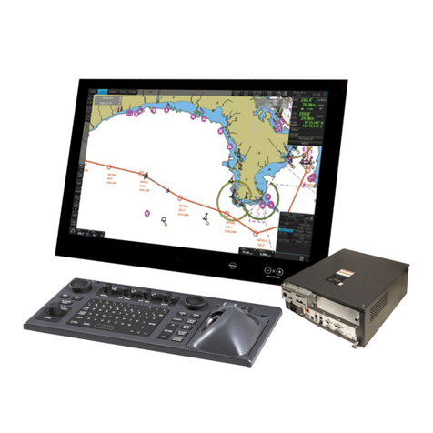
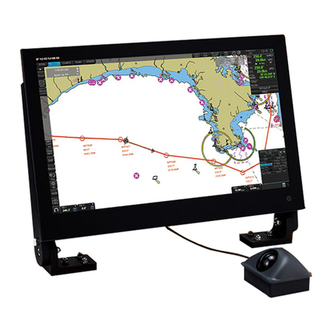
Furuno FICE-100 User manual

Furuno Finland Oy
OPERATOR'S MANUAL
FURUNO FINLAND
ICE RADAR FICE-100
www.furuno.fi

2
Contents
FOREWORD.......................................................................................................................................4
A Word to the Owner of the Furuno Finland Ice Radar FICE-100 .................................................4
Features............................................................................................................................................4
1. SYSTEM CONFIGURATION........................................................................................................5
2. GRAPHICAL USER INTERFACE (GUI)......................................................................................6
2.1 Operating mode selections.........................................................................................................7
2.2 Sensor Information.....................................................................................................................7
Selection of Sensor source...........................................................................................................7
Dead reckoning............................................................................................................................8
2.3 Ice filter parameter adjustments.................................................................................................9
2.4 Cursor position indicator............................................................................................................9
2.5 Local time ................................................................................................................................10
2.6 EBL and VRM .........................................................................................................................10
2.6.1 Activation of EBL and VRM............................................................................................10
2.6.2 Fixing VRM and EBL.......................................................................................................10
2.6.3 Removing EBL and VRM from display...........................................................................11
2.7 Display mode selections...........................................................................................................11
2.8 Color palette selections............................................................................................................12
2.8.1 Choosing Predefined palette .............................................................................................12
2.8.2 Customized palette............................................................................................................12
3. USE OF FUSION SCANS AND MODES....................................................................................13
3.1 Adjusting Fusion Scans............................................................................................................13
3.2. Radar Modes...........................................................................................................................13
3.2.2Use of Radar mode Lead....................................................................................................14
4. SCREEN SHOTS...........................................................................................................................15
4.1 How to take screenshots...........................................................................................................15
4.2 How to export screenshots.......................................................................................................16
4.3 How to delete screenshots........................................................................................................16
5. TARGETS......................................................................................................................................17
5.1 How to get targets on display...................................................................................................17
5.2 How to get target’s information on display .............................................................................17
5.3 How to get past track of target on display ...............................................................................17
5.4 How to create fixed target (FT)................................................................................................18
5.5 How to remove fixed target (FT).............................................................................................18
6. RECORDINGS..............................................................................................................................19
6.1 How to select date and time for record viewing ......................................................................20
3
6.2 How to view screen shots.........................................................................................................20
6.3 How to select time period for exporting recordings ................................................................20
6.4 How to copy recordings to external memory...........................................................................20
7. Other functions...............................................................................................................................21
7.1 How to change time zone.........................................................................................................21
7.2 Shut down or restart of FICE-100 ice radar.............................................................................21
7.3 How to upgrade software.........................................................................................................21
Version E, 07 JUN 2019

4
FOREWORD
A Word to the Owner of the Furuno Finland Ice Radar FICE-100
Congratulations on your choice of the FURUNO Finland Ice Radar FICE-100.
Your equipment is designed and constructed to meet the rigorous demands of the marine
environment. However, no machine can perform its intended function unless properly operated and
maintained. Please carefully read and follow the operation and maintenance procedures set forth
in this manual.
Thank you for considering and purchasing FURUNO Finland.
We would appreciate feedback from you, the end-user, about whether we are achieving our
purposes.
Features
The Furuno Finland lce Radar is a hybrid ice radar. It is based on the normal Furuno ARPA radar,
and captures a copy of the raw radar signal from the ARPA processor. The normal operation of the
ARPA radar is not affected.
The Ice Radar is not a navigational device. It is a supplementary system for the specific task of
observing ice conditions by radar.
If you like to know more about the Ice Radar capabilities please contact to Furuno Finland Oy
(www.furuno.fi).

5
1. SYSTEM CONFIGURATION
Interconnection diagram

6
2. GRAPHICAL USER INTERFACE (GUI)
User interface sections
1.
Heading mode, vector time selection, range/scale selection and Range Rings ON/OFF
2.
Navigational data
3.
Ice filter parameter adjustment
4.
Cursor position indicator, Parallel Index lines settings, local time, software version number
5.
EBL/VRM indicators
6
TM reset, Center ship, Display palette selection, Targets, Screenshots and Recording and System
buttons

7
2.1 Operating mode selections
o.
Description
1.
Motion mode select - Available modes:
Head Up TM
Head Up RM
North Up TM
North Up RM
2.
Vector –Selection of vector length (Off, 1 min, 3 min, 6 min)
3.
Range/Scale indicator –Shows the range used in Radar display.
2.2 Sensor Information
You can find sensor information on upper right corner of display.
Note that available sensor information is depending on connected sensor.
Information available:
HDG = Heading
SPD = Speed (either ground stabilized or through water) bi-directional
speed, if available from sensor.
COG = Course over ground
SOG = Speed over Ground
POSN = Position
Selection of Sensor source
You can select source of sensor information for FICE-100.
Move cursor over sensor information area and click left mouse button to open menu. A menu with selection
“Select Sources” appears. Choose the selection, you will have one of following windows on screen.
Use arrow up and down to select desired sensor in highest priority. Click Apply button to confirm your
selections.

8
Dead reckoning
If no heading, speed and/or position information is received from sensors then those values can be entered
manually.
Touch sensor information area to open menu, select Set Manual heading and/or Set Manual speed to set
them. See also chapter “Position Fixing” for more information about Dead reckoning.

9
2.3 Ice filter parameter adjustments
These parameters affect the behavior of the Ice filter. The following items are explained later in this manual.
Description
Echo –Move cursor just over Echo box and click left mouse button,
following controls appear:
Brightness –adjust brightness of Ice layer
Contrast –adjust contrast of ice layer.
Gamma –adjust linearity of ice color.
Palette –select color palette for ice layer.
Radar Mode:
Lead
Iceberg
For more information, see chapter 3.2.
Adjust number of Scans –how many overlapping radar scans are used for
the Ice echoes
Note, if Fusion mode is “Iceberg”, Fusion scans is set as 1.
Effect
3D and Edge to emphasis shapes of ice and to find easy going trails on
ice.
Equalize
Balancing ice layer picture
2.4 Cursor position indicator
You can find cursor position on lower right corner of display.
Description
Cursor position display (LAT, LON) and range and bearing from own ship position

10
2.5 Local time
To change between local time and UTC, move cursor over time zone indication and click left mouse button
to toggle between local time zone and UTC.
Note, time adjustment is using ZDA sentence received from EPFS device.
2.6 EBL and VRM
2.6.1 Activation of EBL and VRM
There are two set of EBL/VRM which can be used to complete distance and direction measurements. To
activate EBL1 take cursor next to EBL1 box and click left mouse button. Cursor is automatically moved to
radar area where you can adjust EBL1. To fix EBL1 click again left mouse button. If you want to cancel
adjustment click right mouse button. Do the same way with VRM1 to adjust and fix VRM1.
Adjustment of EBL2 and VRM2 is done the same way.
If you want adjust both EBL1 and VRM1 at the same time in activation use right mouse button.
T = reference North R = reference heading line
2.6.2 Fixing VRM and EBL
To fix EBL and VRM.
Take cursor next to text EBL and click right mouse button.
Choose desired presentation mode.
No.
Kuvaus
1.
Ship Center (empty) –fixed North Stab EBL.
2.
Ground Stab (STAB G) –geographical fixed EBL/VRM
3.
Heading Stab (STAB H) –EBL and VRM take to desired location to fix there. EBL
and VRM will follow own ship movements changing EBL based on own ship
heading line.
4.
North Stab (STAB N) –EBL and VRM take to desired location to fix there. EBL and
VRM will follow own ship movements changing EBL based on north orientation.

11
2.6.3 Removing EBL and VRM from display
Take cursor either EBL1 or EBL2 text. Click right mouse button to open menu shown below.
EBL/VRM Off removes only selected tool on display.
All Off removes both tools on display.
2.7 Display mode selections
No.
Description
1.
Click on TMReset to reset vessel position to reset margin.
2.
Click on Center ship to place vessel on the center of screen.
3.
Use Display to select Day or night palette.

12
2.8 Color palette selections
2.8.1 Choosing Predefined palette
You can select predefined color palette for ice layer by clicking Echo button and select in Palette box by
thumb wheel desired palette.
2.8.2 Customized palette
If you want to adjust palette (Hue, Saturation and Brightness) manually, click Palette button to open Palette
window shown below. Adjust curves with cursor and then click Save as Custom button.

13
3. USE OF FUSION SCANS AND MODES
The surrounding weather condition, ice and sea state and of course the installation height of the radar
antenna effects on the image processing on Ice radar. Ice radar FICE-100 has option “Lead” for Radar mode
together with number of scans to process video image on screen. You can change between Lead and
Iceberg Radar modes and see the result on real time on the screen. This is the best way to achieve the most
efficient image to detect ice. Fusion scans are motion compensated.
You can also tune brightness, contrast and gamma. These controls affect the clarity of the image.
Below you will find instructions on how to adjust Fusion Scans, descriptions of the Radar Modes and some
examples on how to use them.
3.1 Adjusting Fusion Scans
No.
Description
1.
You can adjust Fusion Scans by moving the cursor over Fusion Scans and selecting the number of
Scans by using scroll wheel of mouse.
Note: If Fusion Modes is set to iceberg, Fusion Scans cannot not adjust.
3.2. Radar Modes
Radar modes can be changed by moving the mouse cursor over Radar Modes and selecting the mode by
using scroll wheel of mouse. Below you will find explanations for each Radar Mode.
Mode
Description
Iceberg
This mode is used to find iceberg.
Lead
This mode is used to remove temporary noise. The edges of echoes are
displayed.
Note that moving echoes (objects) may be lost. This can be used for example
when you need a sharp image of faint trails through ice.

14
3.2.2Use of Radar mode Lead
Below you can find radar image where leads/old tracks can be seen:
Vessel old
track
Slush ice
Thick
solid ice

15
4. SCREEN SHOTS
No.
Description
1
Click on Screenshots to capture single or multiple screenshots covering the whole display.
Screenshots –function allows you to capture single or multiple screenshots of the whole display in JPEG -
format. These screenshots can be also exported to an external memory, such as an USB stick.
Screenshots –function is operated by clicking Screenshots with your mouse and selecting Take, Export or
Delete all.
4.1 How to take screenshots
No.
Description
1.
Click on Screenshots to open the screenshots menu
2.
Click on Take to capture single or multiple screenshots. You can see the number of taken
screenshots in the Export –box.

16
4.2 How to export screenshots
No.
Description
1.
Click on Screenshots to open the screenshots menu
2.
Click on Export to move the captured screenshots to an external memory, such as an USB stick.
You can export the screenshots by following these steps:
1. Connect the external memory to your workstation
2. Click Screenshots and Export
3. The screenshots have been successfully moved to an external memory, when the number
under Export goes back to zero.
4. On your external memory the screenshots can be found in folder “\exports\screenshots\”.
The filenames of screenshots indicate the date and time of capture e.g.
“20140221T111738025UTC.jpg”
Note: Clicking Export moves the screenshots to an external memory and removes them from your
workstation.
4.3 How to delete screenshots
No.
Description
1.
Click on Screenshots to open the screenshots menu
2.
Click on Delete all to delete all captured screenshots.
If Delete all is selected, “Are you sure?” dialogue appears, and has to be clicked again for
confirmation. After Deleting all, the number under Export will return to zero.

17
5. TARGETS
On FICE-100 both Tracked Targets and AIS targets can be shown. Targets can be received from Furuno
FAR-2xx7, FAR-2xx8, FAR-15x8 or FAR-3000 (TT) and AIS transponder (AIS target).
AIS target symbol TT symbol
5.1 How to get targets on display
Description
Click Targets and select Show/Hide.
5.2 How to get target’s information on display
Move cursor on desired target and click right mouse button, select Info from menu that appears.
5.3 How to get past track of target on display
Description
Click Target and select Past track to get track ON/OFF. Length of target’s
past track is 15 min.

18
5.4 How to create fixed target (FT)
Description
Click Targets and select Create fixed to define target desired location.
Move cursor desired location and click left mouse button to create target.
Fixed target’s id is FT X (X = order number of target (1,2,3…)).
5.5 How to remove fixed target (FT)
Move cursor on fixed target (FT x) and click right mouse button. Select Cancel target from the menu.

19
6. RECORDINGS
Recordings are done automatically on hard disk of system.
User can view recordings with the system or save them on external memory device for later use.
Description
Click Screen rec to open record viewer.

20
6.1 How to select date and time for record viewing
Use ruler on lower part of display to set desired date and time for record viewing.
6.2 How to view screen shots
Click “Play” button to start viewing. Click “Stop” button to stop viewing.
6.3 How to select time period for exporting recordings
Time period for copying recording(s) to external memory device is done following way:
1. Use ruler on lower part of display to set desired date and time define starting point for copying then
click “Set selected” button in From field.
2. Use ruler on lower part of display to set desired date and time to define ending point for copying then
click “Set selected” button in To field.
6.4 How to copy recordings to external memory
Copy of recordings is done following way:
1. Set desired time period for recordings (export range).
2. Click “Export to USB” button on upper right corner.
3. Next window you can check that time period is set correctly.
Note, that video recording which is longer than one hour is divided automatically one hour periods,
i.e. there are more than one file for video recording.
4. Connect external memory to USB port.
5. Insert pass word for encryption. Files are compressed before they are stored to external memory.
6. Name of recordings on external memory are ”date and time of selected period”.
7. You can view recordings any other device. Before viewing uncompress recordings using some
application (like, WinZip, 7-zip, etc.).
Other manuals for FICE-100
1
Table of contents
Other Furuno Marine Equipment manuals

Furuno
Furuno AUTOPILOT FAP-300 User manual

Furuno
Furuno NAVpilot-300 Installation guide

Furuno
Furuno FE-700 User manual

Furuno
Furuno IF-1002 User manual

Furuno
Furuno FELCOM 70 User manual

Furuno
Furuno MFD8 Manual

Furuno
Furuno FW-200 User manual

Furuno
Furuno ETR-10N User manual

Furuno
Furuno FCV-1200L User manual

Furuno
Furuno FE-881 II User manual

Furuno
Furuno FCV-295 User manual

Furuno
Furuno LH-3000 User manual

Furuno
Furuno VR-7000 User manual

Furuno
Furuno NAVpilot 711C User manual

Furuno
Furuno GS-100 User manual

Furuno
Furuno VR-7000 User manual

Furuno
Furuno FI-302 User manual

Furuno
Furuno FI-303 User manual

Furuno
Furuno FA-30 Assembly instructions

Furuno
Furuno FMD3100 Manual