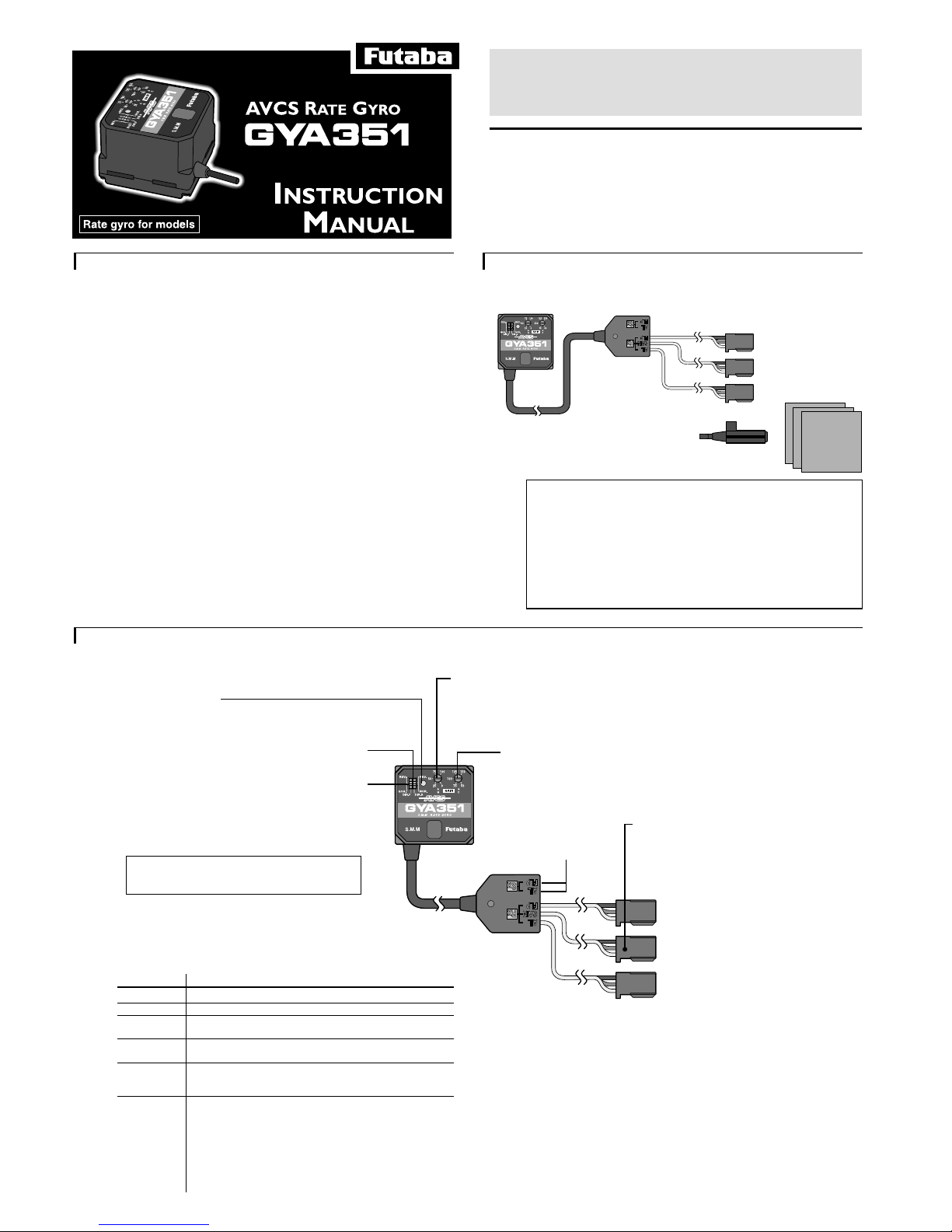
FUTABA GYA351 User manual

• No part of this manual may be reproduced in any form without prior permis-
sion.
• The contents of this manual are subject to change without prior notice.
• This manual has been carefully written. Please write to Futaba if you feel that
any corrections or clarifications should be made.
Thank you for buying a GYA351 AVCS gyro.
Before using your new gyro, please read this manual thoroughly and
use the gyro properly and safely. After reading this manual, store it
in a safe place.
1M23N07404
FOREWORD
1
The GYA351 is a high performance, compact, and light weight
AVCS gyro developed for model aircraft ailerons, especially two
servos FLAPRON wing, control. Integrated sensor and control
circuit make it easy to mount.
Servos:
Gyro performance largely depends on the servo used. The faster
and more responsive the servo, the higher the speed and the
better the sensitivity and performance of the gyro.
Features
•AVCS used
Forward, climb, descent, back, knife edge, and other flying attitudes are main-
tained even when the wind shifts. Therefore, since meeting rudder is almost
completely unnecessary, flying is easy. At the same time, the gyro automatically
corrects bad tendencies of the aircraft.
•SMM gyro sensor
Newly developed very low drift SMM (Silicon Micro Machine) gyro sensor
practically eliminates trim changes during flight.
•Remote gain and mode switching functions
Remote gain function lets you switch the gyro gain from the transmitter. AVCS
mode/Normal mode/Gyro OFF can also be switched from the transmitter.
•Integrated type, compact size, and light weight
Compact size (27x27x20mm) and light weight (32g) have been achieved by the
use of high density mounting technology.
•Conductive resin case improves EMC resistance (electrostatic,
electromagnetic wave interference).
SET CONTENTS
2
•GYA351 •Double-sided
tape (3 sheets)
The GYA351 comes with the following accessories:
•Mini screwdriver
(for adjustments)
GYA351 Ratings
(Integrated sensor type AVCS rate gyro)
• Control system:
Digital advanced PI (Proportional Integration) control
• Gyro sensor:
SMM (Silicon Micro Machine) system vibration gyro
• Operating voltage: +4 to +6VDC
• Dimensions: 27 x 27 x 20mm
• Weight: 32g (including connector)
• Functions:
Gyro operation direction switch, Gyro gain trimmer, Control gain
trimmer
NAME AND FUNCTION OF EACH PART
3
•Monitor LED
Monitors the operating status of the GYA351. See the table
below for the display contents.
•Gyro direction of operation selector
switch (ch1)(DIR.A)
•Gyro gain trimmer (G GAIN)
Adjusts the gyro gain. Gain adjustments are made from the transmitter. In this case,
the value set with this trimmer becomes the reference and the gain can be adjusted by
changing the servo deflection angle setting of the transmitter gain adjustment channel.
When the trimmer is turned clockwise, the gain increases. Adjust the gain to the
maximum value at which hunting does not occur.
•Control gain trimmer (C GAIN)
Adjusts the steering signal controlled variable. The effect of the rudder when
the gyro is turned on can be adjusted. When the trimmer is turned clockwise,
the controlled variable increases.
•Gain switching connector (red)
Gyro gain switching signal input connector.
Connects to the receiver gain switching channel
output connector. The signal from this connector is
also used to switch the AVCS and Normal opera-
tion modes simultaneously with gain switching.
•Ch6 input connector (black)
Connects to ch6 servo output connector of
the receiver.
•Servo output con-
nector
Connects the corresponding
servo.
(Monitor LED display)
LED display Gyro operation status
Rapid flashing Displayed while data is being initialized at power ON.
Steady light Shows that the gyro is operating in the AVCS mode.
Off Shows that the power is OFF, or the gyro is operating
in the Normal mode.
Slow flashing Displayed when a control signal is input from the transmitter.
At this time, the servo does not operate.
Double flash In the AVCS mode, displayed when the signal from the
transmitter deviates from the neutral signal memorized
at the gyro. Also displayed when a stick is operated.
Single flash Displayed when the AVCS function is reset, and a neutral signal
is sent to the servo. The LED flashes once when the gain
selector switch was quickly switched between the Normal and
AVCS positions three or more times and then left in the AVCS
position, or when a transmitter stick was quickly moved to the
left and right three or more times. After this display is per
formed, the servo moves to the neutral position. This display
also flashes when the operation direction or control selector
switch was moved.
GYA351 operation modes
The GYA351 has two operations modes: AVCS mode and Normal mode.
Normal mode
This mode performs general proportional control operation. For instance, it controls the gyro
so that changes are countered when the attitude of the aircraft is changed by cross-wind, etc.
AVCS mode
This mode performs both proportional and integrated control operation The difference
between Normal mode and AVCS mode operation is that whereas the Normal mode only
counters changes in attitude, the AVCS mode returns to the original controlled variable
simultaneously with countering changes in attitude. For example, during knife edge flying,
aileron and elevator meeting rudder is normally necessary, but in the AVCS mode, meeting
rudder is performed automatically by the gyro.
Also, in the AVCS mode, high-speed control is possible, but when the usage method is
incorrect, unintended operation may be performed. Before use, gain a thorough understand-
ing by reading the Usage Precautions and Operation Instructions.
•Gyro direction of operation selector
switch (ch6)(DIR.F)
Selects the direction of operation of the gyro. If the
servo moved when the fuselage was moved in the
aileron axis direction and the servo moved to cancel
this movement, the direction of operation is matched.
If the aircraft is flown while the direction of opera-
tion is wrong, the gyro may apply reverse rudder
and is very dangerous.
•Ch1 input connector (black)
Connects to ch1 servo output connector of
the receiver.

GAIN AND OPERATION MODE SETTING
4
The relationship between the travel adjustment functions (ATV,
AFR) settings and gyro gain when the gyro gain is switched using
the transmitter switching channel is shown below.
100%
40%
70%
0%
40%
100%
100%
50%
0%
50%
25%
70% 50% 25%
0%
0%
100%
0%
50%
Operation mode
Transmitter
ATV, etc. setting Gyro gain
(Forward or down)
(Back or up)
Gyro
OFF
Gyro
OFF
NORMAL OFF AVCS
When 100% set When 50% set
(Gyro gain trimmer position)
This figure shows the case
when the gain setting channel
reverse function is set to Nor-
mal. When this function is set to
Reverse, the switch directions
are reversed. (When Futaba
proportional set used)
Gyro OFF setting:
As shown in the figure, when the ATV rate of the gain setting channel switch is
0% or less, the gyro gain becomes zero. When you want to turn off the gyro, set
to this range (40% or less).
AVCS mode gain setting:
When the ATVB rate is 40% or more, the gyro operates in the AVCS mode. The
actual gyro gain changes based on the gyro gain trimmer setting of the gyro itself.
When the gyro gain trimmer is set to 100%, the gyro gain becomes 100% at
100% ATV rate and becomes 50% at 70% ATV rate. When the gyro gain trim-
mer is set to 50%, when the ATV rate is 100%, the gyro gain becomes 50% and
when the ATV rate is 70%, the gyro gain becomes 25%.
Normal mode gain setting:
When the ATVA rate is 40% or more, the gyro operates in the Normal mode. The
gyro gain setting can be adjusted the same as in the AVCS mode.
When gain switching from transmitter function
not used:
The gyro gain switching connector is not connected to the receiver. In this case,
the gyro operates in the Normal mode. The gyro gain is set using the gyro gain
trimmer.
OPERATION INSTRUCTIONS
5
Mount and adjust the GYA351 as described below.
Gyro Mounting Method
Make a gyro bed so that the bottom of the gyro body is perpendicu-
lar to the direction of the axis to be controlled and securely install
the gyro with the accessory double-sided sponge tape at a position
at which vibrations are minimal.
•If this axis changes, the gyro also corresponds to linkage of
other axis.
•Aileron control
Usage Precautions
•When taking off and landing, always switch to the Normal mode.
Taking off and landing in the AVCS mode is dangerous.
•When using an air brake, use the gyro in the Normal mode. If
used in the AVCS mode, the aircraft will roll.
•When the gyro is ON, the servo operating angle increases.
Increase the travel width of the flight control surfaces so that
they will not strike the linkage even when the servo is operated
to its maximum deflection angle.
•Always use the miniature screwdriver supplied to oper-
ate the GYA350 selector switches and trimmers. Do
not apply excessive force.
Beginner setting
(When there is no vacant receiver channel)
Use this setting method when there is no vacant receiver channel.
Use the GYA351 in the Normal mode only.
Mounting to fuselage and initial setting
1. Gyro mounting
Mount the gyro to the axis in accordance with "Gyro Mounting Method".
2. Gyro connection
•Do not connect the gain switching connector.
•Connect to the receiver output of ch1.
•Ch1 servo.
50% 100%
3. Trimmer setting (Initial)
Set the gyro gain trimmer to about the 50% position.
Set the control gain trimmer to about the 100% position.
4. Power ON procedure
Turn on the transmitter power, then turn on the receiver and gyro power.
After the gyro power is turned on, initialization is automatically performed
for about three seconds. Never move the aircraft during this period.
During initialization, the gyro monitor LED flashes.
5. Gyro direction of operation check
Tilt the aircraft about the aileron axis, and check if the gyro applies rudder
in the direction opposite the direction of tilt.
If the rudder moves in the opposite direction switch the gyro
direction of operation selector switch.
Gyro direction of operation
selector switch (ch1)(DIR.A)
Flight adjustments
1. Power ON procedure
Turn on the transmitter power, then turn on the receiver and gyro power.
After the gyro power is turned on, initialization is automatically performed
for about three seconds. Never move the aircraft during this period.
2. Trimming
Fly and trim the aircraft.
If there is a large mechanical deviation, correct the linkage. Connect the
linkage so that the servo horns are as close to the center position as
possible and the transmitter trimmers are also at the center position.
3. Gyro gain adjustment
When the servo hunts, the gyro gain is too high. Lower the
gain with the gyro gain trimmer until the hunting stops. The
gyro will display best performance at a gain just before
hunting occurs. Perform trimming by flying the aircraft
repeatedly.
4. Rudder effect adjustment
Use the transmitter steering angle adjustment function to
adjust the rudder effect.
However, when the rudder effect is substantially different
from that when the gyro was not mounted, adjust it with the
control gain trimmer.
When the gyro is turned on, the rudder will feel sluggish. Adjust the
control gain so that the rudder effect matches the rudder effect when the
stick is set to its maximum position. When the control gain is increased,
the rudder effect increases.
Gyro gain trimmer
(G GAIN)
Control gain trimmer
(C GAIN)
Standard Setting
(Setting using all GYA351 functions)
This standard setting controls gain switching and AVCS/ Normal
gyro operation mode switching from the transmitter.
However, when using the GYA351 with its GYA350 sister product,
and mounting gyros in three axis, three vacant channels are neces-
sary for gain and operation mode switching. When there are not
enough vacant channels, do not connect the gain switching connec-
tor and operate the gyro in the Normal mode only. The gain of the
gyros of two axes can also be switched simultaneously by using a
branch cord.
Mounting to fuselage and initial setting
1. Gyro mounting
Install the gyros to the axes in accordance with "Gyro Mounting Method".
•Connect to the receiver output of ch6.
•Ch6 servo.
Aileron axis Gyro direction of operation
selector switch (ch6)(DIR.F)

When there is no vacant channel that can be used for gain switching,
"Standard setting" cannot be performed. See "Beginner setting".
When gyros are installed in two or three axis, and there are not enough
vacant channels, use a branch cord to simultaneously switch the gain of
two axis.
3. Trimmer setting (Initial)
Set the gyro gain trimmer to the 100% position.
Set the control gain trimmer to about the 100% position.
4. Gain setting
Set the gain as described below.
100% 100%
(Gain setting with T8UAPS example 2)
The following describes how to use channels 5, 7, and 8 to switch
the gain of the rudder, aileron, and elevator axis. (When GYA350
being used in the rudder and elevator.)
1.Call the transmitter 5ch ATV screen and
make the following setting:
- Set the CH5 switch rate for both directions to
70%. This sets the gyro gain to 50%.
•In the switch forward position, the gyro operates
in the AVCS mode and in the switch backward
position, the gyro operates in the Normal mode.
2.Call the transmitter PMIX-1 screen, and make
the following settings:
- Activate PMIX1.
- Set master channel to OFS.
- Set slave channel to CH7.
- Set mixing rate to +70%.
- Select switch SW-E.
- Select switch direction DOWN.
3.Call the transmitter PMIX-2 screen, and make
the following settings:
- Activate PMIX-2.
- Set master channel to OFS.
- Set slave channel to CH7.
- Set the mixing rate to -70%.
- Select switch SW-E.
- Select switch direction UP.
4.Lock the transmitter CH7 knob in
the 0% position. This sets the
aileron axis gyro gain to 50%.
•When switch SW-E is in the forward
position, center position, and
backward position, the GYA350
gyro operates in the AVCS, OFF,
and Normal modes, respectively.
5.Call the transmitter PMIX-3 screen, and make
the following settings:
- Activate PMIX-3.
- Set master channel to OFS.
- Set slave channel to CH8.
- Set mixing rate to +70%.
- Select switch SW-E.
- Select switch direction DOWN.
6.Call the transmitter PMIX-4 screen, and make
the following settings:
- Activate PMIX-4.
- Set master channel to OFS.
- Set slave channel to CH8.
- Set mixing rate to -70%.
- Select switch SW-E.
- Select switch direction UP.
7. Lock the transmitter CH8 knob in
the 0% position.
This sets the elevator axis gyro
gain to 50%.
•When SW-E is in the forward,
center, and backward positions, the
GYA350 operates in the AVCS, OFF,
and Normal mode, respectively.
Normal
OFF
AVCS
Normal
OFF
AVCS
CH7
knob
CH8
knob
(Gain setting with T8UAPS example 3)
The following describes how to use CH7 to switch the aileron and elevator
gain and CH8 to switch the rudder axis gain. (When GYA350 being used
in the rudder and elevator.)
The aileron and elevator gyros gain switching connector is connected to
receiver CH7 by branch cord. When air brake is ON, the aileron and
elevator axis gyros must be set to the Normal mode.
1.Call the transmitter PMIX-1 screen, and make
the following settings:
- Activate PMIX1.
- Set master channel to OFS.
- Set slave channel to CH7.
- Set mixing rate to +70%.
- Select switch SW-C.
- Select switch direction UP.
2.Call the transmitter PMIX-2 screen, and make
the following settings:
- Activate PMIX-2.
- Set master channel to OFS.
- Set slave channel to CH7.
- Set the mixing rate to -70%.
- Select switch SW-C.
- Select switch direction C/DN.
3.Lock the transmitter CH7 knob in
the 0% position. This sets the
aileron and elevator gyro gain to
50%.
•When switch SW-C is in the up,
center, and down positions, the
GYA350 operates in the AVCS,
Normal, and air brake ON modes,
respectively.
When you want to set the gain of
the aileron and elevator gyros
independently, adjust the gyro
gain trimmer on the gyros
individually.
4.Call the transmitter PMIX-3 screen, and make
the following settings:
- Activate PMIX-3.
- Set master channel to OFS.
- Set slave channel to CH8.
- Set mixing rate to +70%.
- Select switch SW-E.
- Select switch direction DOWN.
5.Call the transmitter PMIX-4 screen, and make
the following settings:
- Activate PMIX-4.
- Set master channel to OFS.
- Set slave channel to CH8.
- Set mixing rate to -70%.
- Select switch SW-E.
- Select switch direction UP.
6. Lock the transmitter CH8 knob in
the 0% position.
This sets the rudder axis gyro
gain to 50%.
•When SW-E is set to the forward,
center, and backward positions, the
GYA350 operates in the AVCS, OFF,
and Normal modes, respectively.
AVCS
Normal
Normal
Air Brake
Normal
OFF
AVCS
CH7
knob
CH8
knob
(Example of gain setting using T9ZAP)
The following describes how to use vacant channels 5, 7, and 8 to
switch the gain of the rudder, aileron, and elevator axis. (When
GYA350 being used in the rudder and elevator.)
+T1
+J1
AIL
+T3
+J3
ELE
+T2
+J2
THR
+T4
+J4
RUD
+SF
GEA
+LD
FLP
+SE
AU1
+SE
AU2
END
SEL
CTR
TRM
FUNCT CTRLFUNCT CTRL
ENDAIL ELE THR RUD GEA FLP AU1 AU2
ATVATV
NXT
NORMAL
GEA
70 %
70 %
: MODE
: CHANNEL
: RATE A
AINPUT
SRV
B
: RATE B
1.Call the transmitter
function control functions
screen, and make the
following settings:
- Set switch SF to
GEA(5CH) and switch SE
to AU1(7CH) and
AU2(8CH), respectively.
2.Call the transmitter ATV
function screen, and make
the following settings:
- Select GEA(5CH) and
set both RATEA and
RATEB to 70%.
- Set AU1(7CH) and
AU2(8CH) to 70% rate
similarly.
This sets the gain of the aileron,
elevator and rudder axis gyros to
50% each.
•When switch SW(E) is set to the
forward, center, and backward
positions, the GYA350 operates in the
AVCS, OFF, and Normal modes,
respectively. When switch SW(F) is set
to the forward and backward positions,
the rudder axis gyro operates in the
AVCS and Normal modes,
respectively.
Normal
OFF
SW(E) SW(F)
AVCS
Normal
AVCS
5. Power ON procedure
Turn on the transmitter power, then turn on the receiver and gyro power.
Initialization is performed automatically for about three seconds after the
gyro power comes on. Do not move the aircraft during this period. During
initialization, the gyro monitor LED flashes. When the gain selector switch is
set to the AVCS position, the monitor LED changes to a steady light. When
the gain selector switch is set to the Normal position, the LED goes off.
6. Gyro operation direction check
Tilt the aircraft about the control axis, and check if the gyro moves in the
direction opposite the tilt direction.
If the gyro moves in the opposite direction, switch the gyro direction of
operation selector switch.
2. Gyro connection
•Connect to the gain switching channel.
•Connect to the receiver output of ch1.
•Ch1 servo.
•Connect to the receiver output of ch6.
•Ch6 servo.
(Gain setting with T8UAPS example 1)
The following describes how to use the channel 5 switch to switch
the aileron axis gain. (When GYA351 used independently.)
1.Call the transmitter 5ch ATV screen and
make the following setting:
Set the rate of both directions of the CH5
switch to 70%. This sets the gyro gain to 50%.
•In the switch forward position, the gyro operates in the
AVCS mode and in the switch backward position, the gyro
operates in the Normal mode.
Gyro direction of operation
selector switch (ch1)(DIR.A)
Gyro direction of operation
selector switch (ch6)(DIR.F)

Control gain
trimmer (C GAIN)
Flight adjustment
1. Power ON procedure
Turn on the transmitter power, then turn on the receiver and gyro power.
Initialization is performed automatically for about three seconds after the
gyro power comes on. Do not move the aircraft during this period.
2. Trim adjustment
Set the gyro gain switch to the Normal or OFF position. The monitor LED
goes off. Fly and trim the aircraft in this state.
When the mechanical deviation is large, correct the linkage. Connect the
linkage so that the servo horn and transmitter trimmers are in the center
position.
3. Gyro gain adjustment
When the servo hunts, the gyro gain is too high. Lower the gyro gain until
the hunting stops. The gyro displays top performance at a gain just before
hunting begins. Perform trimming by flying the aircraft repeatedly. Adjust
the gain by raising and lowering the transmitter ATV or mixing rate.
4. Rudder effect adjustment
Use the transmitter deflection angle adjustment function to
adjust the rudder effect.
However, when the rudder effect is substantially different
from that when the gyro is installed, adjust it using the control
gain trimmer.
When the gyro is turned on, the rudder will feel sluggish. Adjust the
control gain to match the rudder effect when the stick is set to its maxi-
mum position. When the control gain adjustment amount increases, the
rudder effect increases. Adjust the linkage so that use is possible at a
transmitter deflection angle setting of 70% or more.
5. AVCS side neutral data memorization
After landing the aircraft, set the gain switch to the AVCS position and turn
on the gyro power again and memorize the AVCS mode neutral data at
the gyro. When using flight conditions, verify that the gyro monitor LED
lights under all the flight conditions used. If the LED flashes twice, trim of
that flight condition has changed. Repeat transmitter trim adjustment. This
ends AVCS side setting.
6. Switch to the AVCS or Normal mode,
as desired.
In the AVCS mode, meeting rudder is seldom necessary because trim
changes during knife edge and upside-down flight are compensated for by
the gyro. Conversely, when the aircraft enters a stall condition in the low
speed state, the gyro continues to apply correction rudder and the aircraft
may enter an unintended attitude. To avoid stalling in such a state, return
to normal attitude as soon as possible by increasing engine power and
applying reverse rudder, or switch the gyro to the Normal mode.
Fuselage Maintenance
Precautions
Do not turn the sensitivity trimmer with
too much force.
The trimmer may break. Always use the miniature
screwdriver supplied to make adjustments.
Service the fuselage with a little vibration
as possible.
Fuselage vibration has a very adverse effect on gyro
performance.
Mounting Precautions
Always use the accessory sensor tape to
install the gyro to the fuselage.
This is necessary to securely fasten the gyro to the fuselage
so that operation of the gyro does not transmit unwanted
fuselage vibrations directly to the sensor.
When mounting the gyro, provide a little
surplus so that the gyro connection cables
are not too taut.
If the gyro cables are too taut, the gyro will not display its
full performance. If the gyro peels, control will be lost and
result in a dangerous situation.
When using the gyro with a airplane, install
the GYA351 at least 10cm from the drive
motor and at least 2 cm from the servo.
The drive motor etc. generates strong electromagnetic
noise. This noise may interfere with the gyro sensor and
cause erroneous operation.
Mount the GYA351 so that metals or other
conductive objects do not touch the gyro
case.
The GYA351 uses a conductive resin case to reduce
electromagnetic interference. Because the surface of the
case is conductive, metal objects may cause a short circuit.
Insert the connectors fully.
If a connector works loose due to vibration during flight,
control may be lost and result in a dangerous situation.
Always check the direction of operation of
the servos.
If you attempt to fly the model when a servo operates in the
wrong direction, the fuselage will spin in a fixed direction
and enter an extremely dangerous state.
Operation Precautions
Never move the fuselage for about 3
seconds after turning on the gyro power.
(when using in the AVCS mode)
Since the data inside the gyro is automatically initialized
as soon as the power is turned on, if the fuselage is
moved, the neutral position will change. If this occurs,
turn the power off and on again. When turning on the
power, set the transmitter switch to the AVCS position
FUTABA CORPORATION
Makuhari Techno Garden Bldg., B6F 1-3 Nakase, Mihama-ku, Chiba 261-8555, Japan
Phone: (043) 296-5118 Facsimile: (043) 296-5124
Special Markings
Pay special attention to the safety at the parts of this manual that are indicated by the following marks.
Mark Meaning
Procedures which may lead to a dangerous condition and cause death or serious injury to the
user if not carried out properly.
Procedures which may lead to a dangerous condition or cause death or serious injury to the
user if not carried out properly, or procedures where the probability of superficial injury or
physical damage is high.
Procedures where the possibility of serious injury to the user is small, but there is a danger of
injury, or physical damage, if not carried out properly.
Symbol: ; Prohibited ; Mandatory
When using the gyro in the AVCS mode,
turn off mixing.
For example, if elevator down mixing is used by the air
brake, the gyro will judge that an elevator down signal
was received and will cause the aircraft to dive. In the
AVCS mode, the gyro automatically changes the trim
and, therefore, these mixings are unnecessary. When
mixing is necessary, set so that the gyro enters the
Normal mode when mixing is ON.
Check the operating time of the receiver,
gyro, and servo batteries at the adjust-
ment stage and decide the number of
remaining flights while allowing a margin.
and turn on the transmitter power switch, then turn on
the gyro power.
Do not operate the trim while flying in
the AVCS mode.
When the power is turned on, the GYA351 assumes that
the stick is in the neutral position. If the trim is moved
during flight, the neutral position will change.
Avoid sudden temperature changes.
Sudden temperature changes will cause the neutral
position to change. For instance, do not fly the model
immediately after removing it from inside a heated
vehicle in the winter and an air conditioned vehicle in
the summer. Let the model stand for about 10 minutes
to allow the temperature inside the gyro to stabilize
before turning on the power. Also, consider sudden
temperature changes when the gyro is exposed to direct
sunlight or is installed near the engine. Take measures
so that the gyro is not exposed to direct sunlight.
Do not stall the aircraft.
When the aircraft enters the stall condition, and the gyro
tries to maintain its original attitude by applying full
rudder. This results in assisting the stall. If the nose
remains up and the aircraft stalls when landing, etc., the
gyro will try to maintain that attitude by applying more
up elevator. To avoid this danger, when taking off and
landing, use the gyro in the Normal mode.
Do not use the AVCS mode when taking
off and landing.
From the standpoint of the operation characteristics,
taking off and landing in the AVCS mode is dangerous.
When taking off and landing, use the gyro in the normal
mode.
Using AVCS correctly
The AVCS type gyro controls the attitude of the aircraft by constantly
comparing the transmitter operation signals and the gyro internal
reference signal (transmitter neutral signal). Therefore, for the AVCS
function to operate normally, the rudder neutral signal must be memo-
rized at the gyro before flight.
Neutral signal memorization
There are two methods of memorizing the neutral signal.
[Method 1] When the gyro power is turned on, the signal received
from the transmitter at that time is assumed to be the neutral signal
and is memorized at the gyro. The gyro is normally used in this state.
[Method 2] The neutral position can also be memorized by rapidly
switching the transmitter gain switch between the AVCS and Normal
positions at least three times at an interval of within one second. In
this case, the monitor LED flashes once to show that memorization is
complete.
When the trim was changed during flight, the memorized neutral
position can be updated to the current neutral position by repeating
this operation. When this performing this operation, kept the stick in
the neutral position.
Neutral check method
In the AVCS mode, the servo does not return to the neutral position
even though the stick is returned to neutral. When you want to check
the servo neutral position during linkage neutral check, etc., set the
gain switch to the Normal position, or quickly move the transmitter
stick to the left and right at least three times and immediately return
the stick to the neutral position. A dead zone is produced in servo
operation relative to stick operation. However, this is because the stick
control gain rises and is not an abnormality.
©FUTABA CORPORATION 2001, 1
Other FUTABA Accessories manuals

FUTABA
FUTABA SBS-01TAS User manual

FUTABA
FUTABA WTR-7 User manual

FUTABA
FUTABA RS301CR User manual

FUTABA
FUTABA SBS-01TAS User manual

FUTABA
FUTABA FSU2 User manual

FUTABA
FUTABA GY611 User manual

FUTABA
FUTABA GYA352 User manual

FUTABA
FUTABA GY701 User manual

FUTABA
FUTABA GYA350 User manual

FUTABA
FUTABA SBC-1 User manual
Popular Accessories manuals by other brands

NAPCO
NAPCO GEM-ACM1D Installation instructions addendum

PCB Piezotronics
PCB Piezotronics ICP 113B27 Installation and operating manual

ATN
ATN PS-23 user guide

Benchmark Scientific
Benchmark Scientific myBlock BSH5002 Operation manual

ROSE DISPLAYS
ROSE DISPLAYS CABLE CLIP manual

ROSE DISPLAYS
ROSE DISPLAYS SIDE-LOADING ANOSKYBOX manual