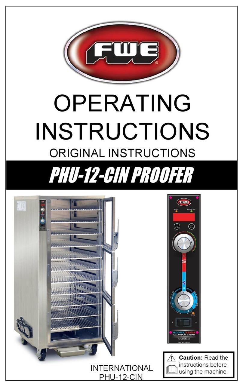
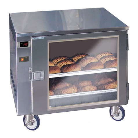
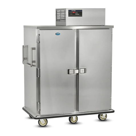
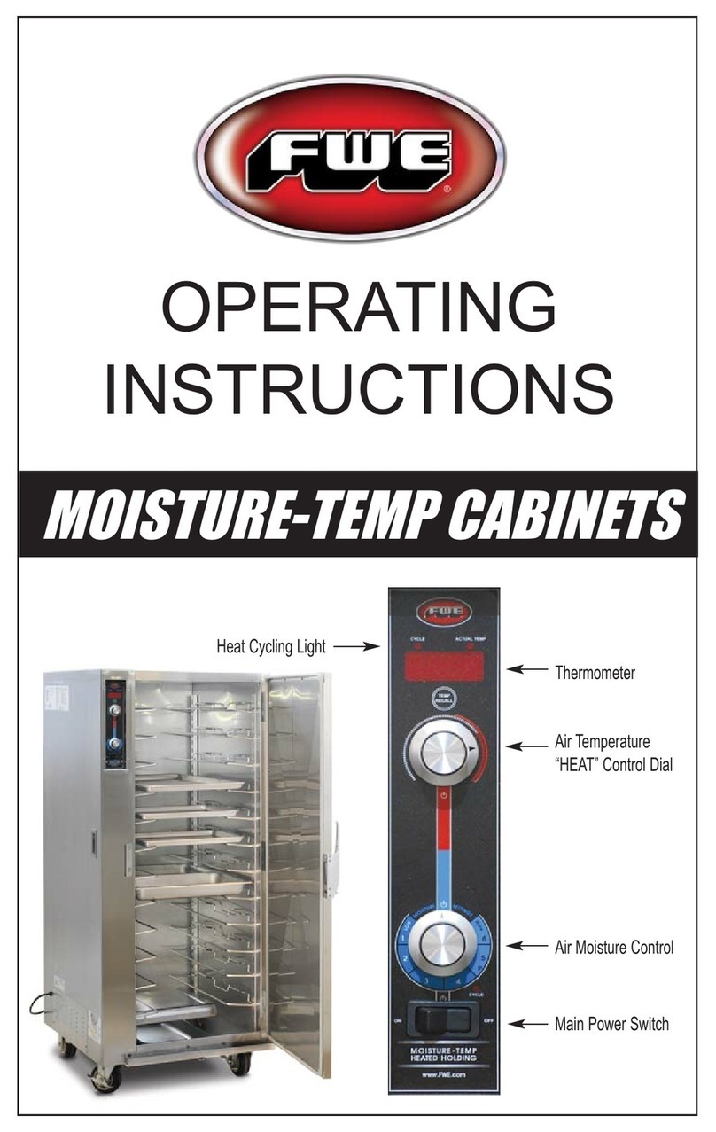
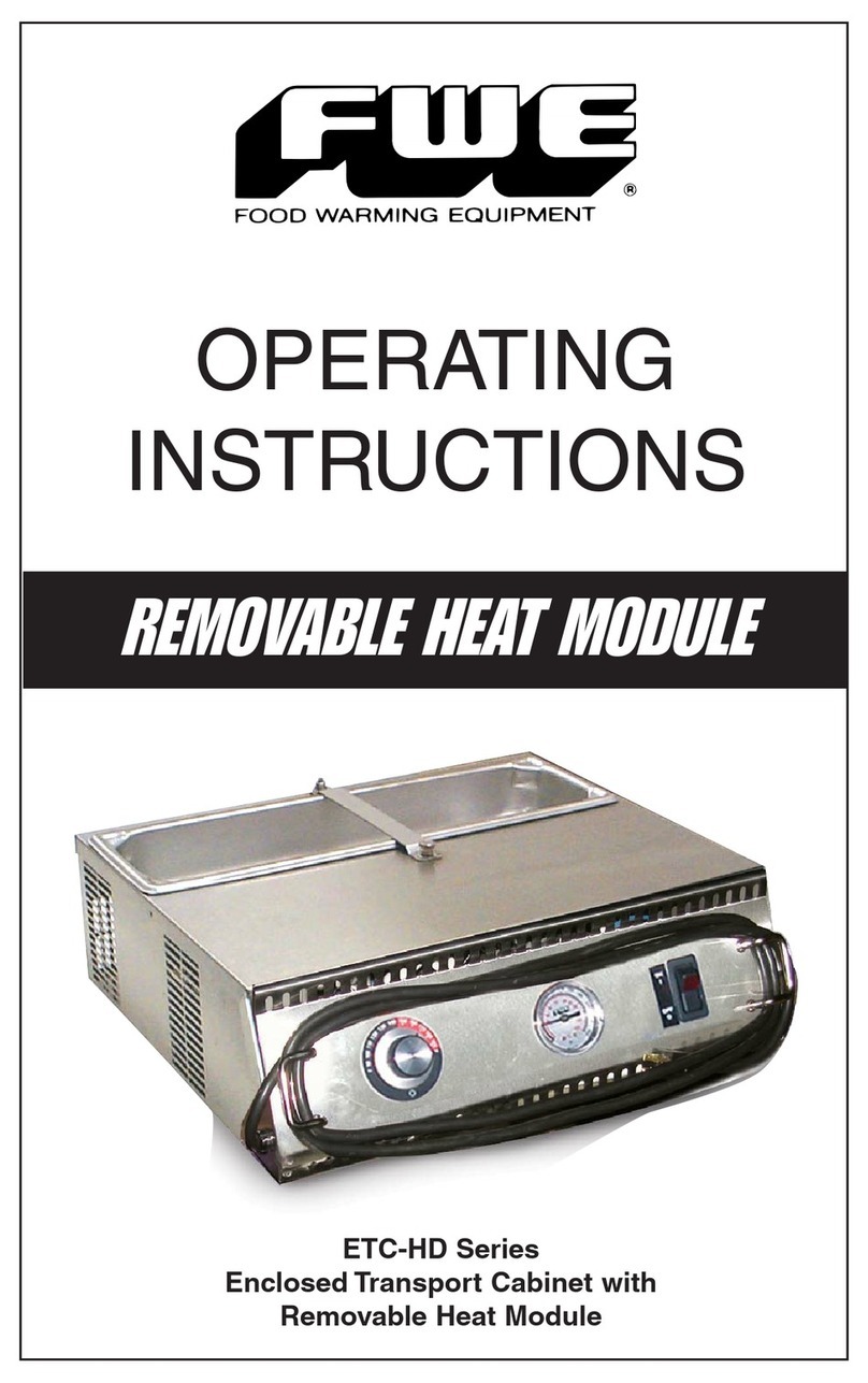
FWE E Series User manual

OPERATING
INSTRUCTIONS
MOBILE BANQUET CABINETS
Dual-Heat Banquet Cabinets:
E SERIES, XL SERIES, and XXL SERIES
C SERIES (for Canned Fuel only)
TM

DUAL-HEAT BANQUET CABINETS
These versatile cabinets allow you to use either
canned fuel or efficient forced air electrical heat.
CONGRATULATIONS...
...and thank you for purchasing an FWE Mobile Heated Banquet
cabinet. E Models are designed for use electrically or with canned fuel.
Your unit has been designed and manufactured under rigid controls to
assure you the most efficient service. It is a full time unit, and may be
used continuously.
Please take a moment to read through this booklet of important
information pertaining to your cabinet. By following a routine of
proper use and care described on the following pages, your cabinet
will last for many years.
IMPORTANT: Your Manufacturer Registration Card must be
returned within 30 days after initial delivery to put warranty into effect.
2
E-600 E-1200

FWE Dual-Heat Banquet Cabinets
MODEL NUMBERS
XL Cabinets accommodate
covered plates up to 12-3/8” diameter
for maximum capacity.
XXL Cabinets accommodate
covered plates up to 13.25” diameter
for maximum capacity.
CAUTION: HOLDING FOOD AT TEMPERATURES
OF LESS THAN 140°F MAY BE DANGEROUS.
TEMPERATURES UNDER 140°F PROMOTETHE GROWTH
OF HARMFUL BACTERIA AND TOXINS IN SOME FOODS.
3
E-960 E-1200 E-1500
E-480 E-600 E-720 E-900

FWE standard models operate on 110/120 volt,
60 Hz, 1 ph, A.C. (unless ordered otherwise), and are equipped
with a three prong grounding cord plug for your protection against
possible shock hazards. Be sure to plug only into a properly
grounded three prong wall receptacle. If you have any questions
with regard to adequate wiring or grounding in your building,
a qualified electrician should be contacted before using your
cabinet. The amperage of your cabinet is stamped on the
name plate attached to the unit.
DO NOT, UNDER ANY CIRCUMSTANCES, CUT OR REMOVE
THE GROUNDING PRONG FROMTHE CORD PLUG.
WARNING: ONLY A QUALIFIED ELECTRICIAN SHOULD
ATTEMPT TO REPAIR OR REPLACE ELECTRICAL
COMPONENTS OR WIRING.
BE SURE THAT MODEL IS UNPLUGGED FROM ELECTRICAL
SOURCE BEFORE REMOVING CONTROL PANEL.
DUAL-HEAT BANQUET CABINETS
SERIAL AND MODEL NUMBER
INSTALLATION AND CARE
UNPACKING
ELECTRICAL REQUIREMENTS AND GROUNDING
These numbers are found on the nameplate (serial tag) affixed
to the lower back of the unit. Please record them in this booklet,
in the space provided on page 13. When ordering parts and/or
service, you will need to provide this information. The voltage
and amperage of the unit are also stamped on the serial tag.
After uncrating your cabinet, remove all tape and padding
which held all doors, shelves, racks, cord, etc., in place during
shipment.
4

Keep your cabinet clean by simply wiping the interior and
exterior, as needed, with a damp cloth or sponge and a mild
soapy solution.
NEVER USE ABRASIVES, ACIDS, OR STRONG CLEANERS.
Do not flood or allow electrical parts to become wet. The interior
tray slide assemblies and humidifier pans are removable for easy
cleaning. A stainless steel cleaner/polish is recommended for
the exterior to maintain a "like-new" appearance.
DO NOT USE WAX OR STRONG CLEANERS ON
DOOR GASKETS OR VINYL TRIM.
CLEANING
CONTROLS
The control panel, recessed above the door(s) at the top of the unit,
is equipped with an adjustable thermostat (to 190° F.) for temperature
selection, an operational range thermometer to show the actual
internal temperature of the cabinet, a 20 amp ON/OFF rocker witch,
a red power indicating light to tell you when the cabinet is plugged
into a power source, and an amber indicating light which goes on
when the heating element is activated and cycling. When operating
in the canned heat mode, place canned fuel only in drawer
receptacles provided at the base of the cabinet interior.
5
CANNED FUEL / ELECTRICAL HEAT SYSTEMS
Top mounted blower system shall include two (2) hi-temp, self-lubricated,
impedance protected, fan cooled blower motors. Interior cabinet body shall be
vented to provide combustion capability for canned fuel. Adjustable louvered vents
assure even heat throughout the cabinet and “No-Fail” combustion, as well as
exhaust of canned fuel fumes. Heating elements and canned fuel system shall
be located at bottom of cabinet to eliminate hot spots and distribute heat equally
throughout cabinet interior. Bottom baffle, back wall and heat distribution tunnel
shall be vented for balanced air circulation when operating on either canned fuel
or electrical power, to prevent overheating of lower shelf. Baffle and solid fuel
drawers shall be contained in the interior of unit to prevent rodent infestation.
Slide-out drawers for solid fuel shall be located under baffle, and shall have
safety stops to prevent tipping/falling out.

GENERAL OPERATING INSTRUCTIONS
ELECTRICAL OPERATION
1) PLUG CABINET INTO A PROPERLY GROUNDED
POWER RECEPTACLE. Turn rocker switch to the
“ON” position.The red indicating light will come on
and remain on until the rocker switch is turned to the
“OFF” position.
2) SELECT A TEMPERATURE SETTING. For most
foods, a holding temperature of 160° - 170° F. should be
adequate.
3) PRE-HEAT CABINET FOR 15-30 MINUTES. When
the amber light goes off, the unit has reached the
temperature which you selected in step 2, and is ready
to load with your HOT foods. Plates may be heated in
the cabinet before dish up, but this will require extra
preheating time. AVOID PUTTING YOUR HOT FOODS
INTO A COLD CABINET! By pre-heating the unit
20-30 minutes before each use, you can be assured
of maintaining the temperature of your food and
obtaining the best results from your cabinet.
4) LOAD THE CABINET. During the loading procedure,
keep the doors closed as much as possible. After
loading is completed, do not open doors again until
you are ready to serve.
5) TRANSPORTING HOT FOODS. Your cabinet is
equipped with a positive transportation latch to assure
safety during transportation. Before moving the cabinet,
keep it plugged in and wait until the amber cycling light
goes off.This recovery takes only a short time, and
allows the internal temperature to again reach the
setting you have selected. As soon as the cycling light
goes off, unplug the cabinet and wheel to serving area.
Plug the cabinet into an electrical outlet at the serving
location (if available), so that the thermostat will
re-activate and automatically hold your pre-selected
temperature.
6

CANNED FUEL OPERATION
GENERAL OPERATING INSTRUCTIONS
1) PLACE CANS OF CANNED FUEL IN RECEPTACLES
PROVIDED IN DRAWER AT BASE OF UNIT.
2) IGNITE CANNED FUEL AND CLOSE CABINET
DOOR. Allow cabinet to heat to desired temperature
before loading with HOT food. NOTE: During the
canned heat mode, the operational thermometer will
register the interior temperature of the cabinet, but
there is no way to exactly regulate the temperature
(the thermostat operates in the electrical mode, only).
Check the thermometer frequently to monitor the interior
temperature. If temperature becomes too hot, reduce the
number of fuel cans inside unit. If temperature is
not hot enough, add additional cans of fuel to the
receptacles provided in the drawers.The number of cans
of fuel required to heat to desired temperature varies,
depending on the model (size) of the unit.
3) LOAD CABINET WITH HOT FOOD AND CLOSE
DOOR UNTIL READY TO SERVE. When serving has
been completed and cabinet is empty, extinguish flame
on canned fuel (snuff with cap or blow out).
Whenever canned heat is in use, do not leave
cabinet unattended.
7

DUAL-HEAT BANQUET CABINETS
For Pre-Plated Meals up to 10-1/2” diameter plates
“E SERIES”
8
74”
(1880)
9.875”
(251)
16.625”
(422)
29.75”
(756)
29.75”
(756)
74”
(1880)
16.625”
(422)
16.625”
(422)
29.75”
(756)
29.75”
(756)
29.75”
(756)
245
(111)
275
(125)
5” 1
64”
(1626)
9.875”
(251)
9.875”
(251)
29.75”
(756)
64”
(1626) 29.75”
(756)
40.5”
(1029)
40.5”
(1029)
52”
(1321)
74”
(1880) 29.75”
(756) 52”
(1321)
16.625”
(422) 74”
(1880) 29.75”
(756) 62.25”
(1581)
340
(154)
5” 2
360
(164)
5” 2
5” 2
6” 2
560
(254)
6” 2
5” 1
64”
(1626)
355
(161)
530
(241)
MODEL
NUMBER
OVERALL EXTERIOR
DIMENSIONS IN. (mm) NO.
OF
DOORS DOOR
SWING
SHIP
WT .
LBS.
(KG)
CASTER
SIZE
CLASS 100
COVERED
PLATES
STACKED
HIGH
SHELF
CLEARANCE
(mm)
SHELF
SIZE HIGH
“H” DEEP
“D” WIDE
“W”
COVERED PLATES:
11”
DIAMETER
COVER & PLATE
HEIGHT
:
3-1/8” 2-5/8”
SHELVES
E-480
48 48 4 3
[A] [A]
E-600
*
60 72 3 5/6
[A] [A] [B]
E-720
72 72 4 3
[A] [A]
E-900
*
90 108 3 5/6
[A] [A] [B]
E-960
96 96 4 3
-[A] [A]
E-1200
*
120 144 3 5/6
[A] [A] [B]
E-1500
*
150 180 3 5/6
[A] [A] [B]
22.25”
x 21.75”
22.25”
x 21.75”
22.25”
x 33”
22.25”
x 33”
22.25”
x 44.375”
22.25”
x 44.375”
22.25”
x 54.75”
[A] Capacities when using covers depend on height of plate and cover. Capacities shown are based on plate and cover height of
3.125” and 2.625” respectively. 11” diameter cover is maximum when not using carriers and stacking directly on shelves.
[B] Available with 5 shelf optional accessory (at time of order @ additional charge) with 9.75” shelf clearance (installed at factory
only). Covered plates then stack 3 high on each shelf. Carriers cannot be used with this optional accessory.
*CP-10 Covered Plate carriers are available for these models.
Dutch Doors are available on the full-size models. Add“D” for the Dutch Door optional accessory.
24”
(588)
24”
(588)
16.5”
(419)
16.5”
(419)
22.25”
(565)
22.25”
(565)
27.5”
(698)
E-480 E-600 E-720 E-900 E-960 E-1200 E-1500
6’
5’
4’
3’
2’
1’
E-480-XL E-600-XL E-720-XL E-900-XL E-960-XL E-1200-XL E-1500-XL
6’
5’
4’
3’
2’
1’
"H"
▲
▲
"H"
▲
▼

DUAL-HEAT XL BANQUET CABINETS
For Pre-Plated Meals up to 12-1/2” diameter plates
9
“E SERIES - XL”
MODEL
NUMBER
OVERALL EXTERIOR
DIMENSIONS IN. (mm) NO.
OF
DOORS
SHIP
WT .
LBS.
(KG)
CASTER
SIZE
CLASS 100
COVERED
PLATES
STACKED
HIGH
SHELF
CLEARANCE
(mm)
SHELF
SIZE HIGH
“H” DEEP
“D” WIDE
“W”
COVERED PLATES:
12
d
”
DIAMETER
COVER & PLATE
HEIGHT
:
3-1/8” 2-5/8”
SHELVES
[A] Capacities when using covers depend on height of plate and cover. Capacities shown are based on plate and
cover height of 3.125” and 2.625” respectively.
[B] Available with 5 shelf optional accessory (at time of order @ additional charge) with 9.75” shelf clearance
(installed at factory only). Covered plates then stack 3 high on each shelf. Carriers cannot be used with this optional accessory.
Plate Carriers are not available for XL Models.
Dutch Doors are available on the full-size models. Add“D” for the Dutch Door optional accessory.
5” 1
5” 2
370
(168)
545
(248)
5” 2
5” 2
6” 2
6” 2
5” 1
74”
(1880) 32”
(813)
74”
(1880) 32”
(813)
31.75”
(806) 290
(132)
64”
(1626) 32”
(813)
64”
(1626) 32”
(813)
44.5”
(1130)
44.5”
(1130)
57”
(1448)
74”
(1880) 32”
(813) 57”
(1448)
74”
(1880) 32”
(813) 69.5”
(1765)
358
(163)
378
(172)
600
(273)
64”
(1626) 32”
(813) 31.75”
(806) 250
(114)
E-480-XL
48 48 4 3
[A] [A]
E-600
-
XL
60 72 3 5
[A] [A] [B]
E-720-XL
72 72 4 3
[A] [A]
E-900
-
XL
90 108 3 5
[A] [A]
E-960-XL
96 96 4 3
[A] [A]
E-1200
-
XL
120 144 3 5
[A] [A] [B]
E-1500
-
XL
150 180 3 5
[A] [A] [B]
24.625”
x 24.625”
24.625”
x 24.625”
24.625”
x 37”
24.625”
x 37”
24.625”
x 49.375”
24.625”
x 49.375”
24.625”
x 61.75”
DOOR
SWING
24”
(588)
24”
(588)
16.5”
(419)
16.5”
(419)
22.25”
(565)
22.25”
(565)
27.5”
(698)
9.875”
(251)
9.875”
(251)
9.875”
(251)
16.625”
(422)
16.625”
(422)
16.625”
(422)
16.625”
(422)
VOLTS 120 120
WATTS 1150 1650
AMPS 9.6 13.8
HERTZ 60 60
PHASE Single Single
G
NEMA
PLUG
ELECTRICAL DATA
E-720, E-900
E-960, E-1200
E-1500
E-720-XL
E-900-XL
E-960-XL
E-1200-XL
E-1500-XL
5-15P
G
5-15P
Dedicated circuit.
E-480
E-600
E-480-XL
E-600-XL
*
PERFORMANCE VALUES
190°
170°
150°
130°
110°
70° 10 20 30 40 50 60 70
T
E
M
P
••
RECOVERY
RECOVERY
PREHEAT
TIME
PREHEAT
75°F to 170°F
APPROX. 55 MIN.
120°F to 170°F
APPROX. 10 MIN.
*Values are for largest model listed
for the E Series.
*
PERFORMANCE VALUES
190°
170°
150°
130°
110°
70°
5 10 15 20 25 30 35
T
E
M
P
••
RECOVERY
RECOVERY
TIME
PREHEAT
75°F to 170°F
APPROX. 24.5 MIN.
120°F to 170°F
APPROX. 10 MIN.
*Values are for mid-size model listed
for E-XL Series.
PREHEAT

DUAL-HEAT BANQUET CABINETS
FOOD SAFETY GUIDELINES
10
FOOD SAFETY & COOKING
Most foods are at risk during preparation and service. As foods
are thawed, cooked, held, served, cooled and reheated, they may
pass several times through the temperature danger zone of
40°F to 140°F (4.4°C to 60°C). Each time food is handled, it
runs the risk of cross-contamination from other food and from
food-contact surfaces, such as: human hands, cutting boards,
and utensils. It is recommended that passing through the
40°F to 140°F (4.4°C to 60°C) zone be done as quickly and
infrequently as possible.
THE FOUR HOUR RULE
The temperature danger zone is considered 40°F to
140°F (4.4°C to 60°C) and rapid bacteria growth zone
is considered 70°F to 120°F (21°C to 49°C). Prevent
potentially hazardous foods from spending more than four
(4) hours combined total time in these zones.The exposure
time is accumulative from time of receiving products until
time it is cooked. Exposure time begins again when food is
fully cooked, held, served, cooled, and reheated.
FOOD
SHOULD NEVER BE REHEATED TWICE!
Food and public health dangers can be avoided with proper food
handling, storage, cooking (rethermalizing) and holding methods.
The key to foodborne illness prevention is constant monitoring of
food temperatures (both storage and internal).
FOOD SAFETY
HACCP is a Food Safety Program that is an effective tool for
safety and quality of food, from processing, receiving, storage,
cooking, holding and serving. By definition, HACCP is:
“
H
AZARD
A
NALYSIS
C
RITICAL
C
ONTROL
P
OINT.”
PROPER FOOD HANDLING - HACCP OVERVIEW

PROBLEM POSSIBLE CAUSE REMEDY
Temperature
too hot
Temperature
not hot
enough
No heat
at all
1
A] Adjustable thermostat set too high
1B] Thermostat needs re-calibrating**
2A] Opening door unnecessarily
2B] Thermostat set too low
2C] Cord plug pulled out from outlet
2D] Fuse blown - no power to outlet
2E] Thermostat out of calibration**
3A] Cabinet not plugged into outlet
3B] Thermostat knob at “ OFF ”
3C] Rocker switch at “ OFF ” position
3D] Fuse Blown - no power to outlet
3E] Thermostat needs replacing
3F] Heating element burned out*
1A] Set thermostat at a lower temperature (no lower than 140°F).
1B] Loosen screw in thermostat knob and remove knob. Adjust set screw
in hollow stem with small blade screwdriver by turning CLOCK-WISE.
1/4 turn lowers temperature approximately 10°F. DO NOT REMOVE
SET SCREW.
2A] Keep door closed and latched shut as much as possible.
2B] Set thermostat at a higher temperature.
2C] Replug cord into proper outlet.
2D] Have a qualified electrician check power and fuse box.
2E] Loosen set screw in thermostat knob and remove knob. Adjust set
screw in hollow stem with small blade screwdriver by turning
COUNTER-CLOCKWISE. 1/4 turn raises temperature approximately
10°F. DO NOT REMOVE SET SCREW.
3A] Plug cabinet into properly grounded electrical outlet.
3B] Adjust thermostat knob to temperature setting required.
3C] Turn switch to “ ON ” position.
3D] Have a qualified electrician check power to fuse box.
3E] Unplug cabinet from electrical source. Loosen set screw in thermostat
knob and remove knob. Remove control panel, disconnect wires from
terminals on thermostat with new one, and re-install control panel and
thermostat knob.
3F] Unplug cart from electrical source. Remove screws holding heating
element in place. Gently pull element away from back wall a few
inches to expose wire connections. Disconnect wires, and replace
element with new one. Reconnect wires, secure element with
screws.
* * NOTE: CALIBRATION IS EXCLUDED FROM FWE WARRANTY. Thermostats on all units are calibrated at the factory prior to shipping.
Due to conditions in transit, beyond our control, occasionally units will need to be re-calibrated prior to use. This is a simple procedure
for which instructions are given above. (1B, 2E)
* Heating element will either function or not function. Only a slight warmth indicates a problem with the thermostat, not the element.
ELECTRICAL HEAT TROUBLE-SHOOTING CHART
Check this list first before you call for service...
11

PARTS LIST
FWE PARTS DEPARTMENT: 815 459 7500
CASTERS PART NUMBER
5” rigid CSTR 5 R-2
5” swivel with brake CSTR 5 SB-2
6” rigid CSTR 6 R-2
6” swivel with brake CSTR 6 SB-2
HARDWARE
Door hinge, lift-off (pr.) HNG L/O
Door latch, paddle latch, non-locking LTH PDL
Door latch, paddle latch, locking LTH PDL LK
Strike for above latch STK LTH 2
Push handle, 21.5” aluminum bar HDL 21.5 AL
Spacers for push handles SPCR125x.330
Bolts, hex head for handles B1/4-20x28NS
Door gasket (by the foot) GSKT DR
Bumper insert, black vinyl BMPR INSERT
ELECTRICAL COMPONENTS
ON/OFF rocker switch, unlighted SWH RCK E1
Blower motor, circulating, 115v MTR JK120 92
(two, located in center of control panel)
5” Fan blade BLD FAN 5B
Blower motor, cooling, 115v MTR-JK 115
(located to the right)
4.5” Fan Blade BLD FAN 4.58
Pilot light, amber/green LT PLT A/G
Thermostat T-STAT H1
Thermostat knob with black arrow KNB H6
Knob for thermostat KNB H1
Thermometer T-METER H1
Extension Cord, 10 ft., 115v CRDSET10/115
Heating element, 16”/500w/115v EL500/115A
SHELVES, PLATE CARRIERS
Wire shelf, 22-1/4” x 21-3/4” SHLF P60
Wire shelf, 24-5/8” x 24-5/8” SHLF P60X
Wire shelf, 22-1/4” x 33” SHLF P90
Wire shelf, 24-5/8” x 37” SHLF P90X
Wire shelf, 22-1/4” x 44-3/8” SHLF P120
Wire shelf, 24-5/8” x 49-3/8” SHLF P120X
Wire shelf, 22-1/4” x 54-3/4” SHLF P200
Wire shelf, 24-5/8” x 61-3/4” SHLF P200X
J-Hook shelf support CLP SHLF-J
*Carrier, uncovered plates, UP-8 UP-8
*Carrier, uncovered plates, UP-10 UP-10
*Carrier, covered plates, CP-8 CP-8
*Carrier, covered plates, CP-10 CP-10
* Note: Carriers are not available on E-480, E-720, E-960 models, nor on any of the XL models.
12

FWE DUAL-HEAT BANQUET CABINETS
SERVICE RECORD
Model Number ______________________
Serial Number ______________________
Date of Purchase ____________________
Notes:
___________________________________________________
___________________________________________________
___________________________________________________
___________________________________________________
___________________________________________________
___________________________________________________
___________________________________________________
___________________________________________________
___________________________________________________
___________________________________________________
___________________________________________________
___________________________________________________
___________________________________________________
___________________________________________________
___________________________________________________
___________________________________________________
___________________________________________________
___________________________________________________
___________________________________________________
___________________________________________________
___________________________________________________
___________________________________________________
___________________________________________________
___________________________________________________
___________________________________________________
___________________________________________________
___________________________________________________
13

FWE DUAL-HEAT BANQUET CABINETS
WIRING DIAGRAM
14
115 Volt
220 Volt

WE OFFER SALES AND SERVICE WORLDWIDE
Food Warming Equipment Company, Inc.
P.O. Box 1001
Crystal Lake, IL 60039-1001
EOI 02 © 2002 Food Warming Equipment Co., Inc. Printed in USA
FWE
Parts Department:
815 459 7500 FAX:
815 459 7989
The best designed . . .
The best built . . .
The best performing units on the market!
◊
◊
◊
◊
◊
◊
◊
◊
◊
Retherm Cabinets
Self-Propelled Transports
Heated Banquet Cabinets
Universal Bulk Food
Cabinets
Utility Carts
Refrigerators, Freezers and
Convertibles
Prisoner & Correctional Tray
Delivery
Hospital Tray Delivery Carts
Portable Bars and Back-ups
Errors subject to correction. All specifications
subject to change without notice.
©02 Food Warming Equipment Company. Inc.

FWE DUAL-HEAT BANQUET CABINETS
LIMITED TWO YEAR WARRANTY
15
FWE / Food Warming Equipment Company, Inc. (Seller) warrants to the original purchaser,
subject to the exceptions and conditions below, that FWE manufactured equipment shall be
free from defects in material or factory workmanship, under ordinary use for the purpose for
which it is designed.The effective warranty period is as follows:
PARTS: Seller will furnish without charge to the original purchaser, FOB Sellers’ factory,
replacement parts for repairs to all new standard catalog products and factory custom /
modified units, which in Seller’s sole judgement, prove defective in materials or workmanship
under normal and proper use with the reserved right to request the return of any part claimed
to be defective, prior to issuing replacement part or authorizing warranty service, for a period
of two (2) years from date of original shipment from Seller’s plant,
except for equipment used
in a Correctional Environment / Facilities, which is warranted for a period of one (1) year
from date of original shipment from Seller’s plant.
LABOR: Seller’s labor warranty shall be performed by a Seller-approved Service Agency who
must contact Seller to obtain a Warranty Service Authorization (WSA) number prior to
performing any repairs. If service is required during overtime periods, the difference between
overtime and standard labor rates shall be paid by the purchaser. Seller does not assume any
responsibility for any charges not expressly authorized, incidental to the repair or replacement
of equipment covered by this warranty, nor charges exceeding, in Sellers sole judgement,
normal and customary amounts. Only approved travel charges will be allowed. Seller’s labor
warranty shall be from the date of original shipment date from Seller’s plant for a period of one
(1) year,
except for equipment used in a Correctional Environment / Facilities which is
warranted for a period of six (6) months.
This warranty is for normal usage and does not apply to any product or parts thereof that have
been misused, altered, or where Seller’s operating instructions or specific voltage is not
observed; nor shall this warranty apply to defective products or parts resulting from accident
following date of original shipment, nor extend to or cover removal, installation, reinstallation or
calibration, or service calls or cost of repairs undertaken by a customer.This warranty is also
subject to the following:
1.] Customer returning the warranty registration card, accompanying Sellers original
shipment, to Seller within thirty (30) days of receipt;
2.] Giving immediate notice of any allegedly defective part or product to Seller; and
3.] Customer, at Sellers request, returning said defective parts or product to Seller.
This is the sole warranty applicable to the merchandise.It is expressly understood that Seller’s
liability hereunder is limited to the repair or replacement, at Seller’s option, of products or parts,
defective materials or workmanship as provided above.Seller’s judgement as to the cause and
nature of any defect will be final.Seller shall in no case be responsible for special or con-
sequential damages or any other obligation or liability with respect to products sold by Seller.
This warranty, as stated above, applies to equipment installed in the Continental United States.
FWE equipment installed outside the Continental United States shall carry parts coverage
only. All labor costs are approved on a discretionary basis, based on like repairs in the
Continental U.S.This warranty shall stand in whole or in part as allowed by law. Any exclusion
of a part of this warranty, as may be allowed by law, shall not void balance of warranty.
This is a limited warranty pursuant to the Consumer Product Warranties Act, 15 U.S. Code. section 2303.
©2003 Food Warming Equipment Co., Inc.
This manual suits for next models
17
Table of contents
Other FWE Commercial Food Equipment manuals
FWE
FWE COMBI-COMPANION LCH-CC Series User manual

FWE
FWE COLD-TEMP URS-10 User manual

FWE
FWE RBQ-96 User manual

FWE
FWE R-AS-10 Operating instructions

FWE
FWE ETC Series User manual

FWE
FWE MOISTURE-TEMP MTU Series User manual

FWE
FWE PST-32 User manual

FWE
FWE HLC Series User manual
FWE
FWE TACO BELL TST-19SL-TB User manual

FWE
FWE ETC-1826-HD Series User manual
Popular Commercial Food Equipment manuals by other brands

Diamond
Diamond ICE35A-R2 manual

ECD
ECD BakeWATCH RACK OVEN V-M.O.L.E SYSTEM Quick reference guide

Hupfer
Hupfer SPA/K operating instructions

SERVIT
SERVIT 423CC1UFNCF user manual

CombiSteel
CombiSteel 7178.3120 User and maintenance instructions

Structural Concepts
Structural Concepts Oasis BV3632 user manual