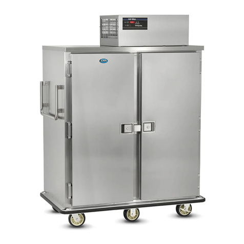
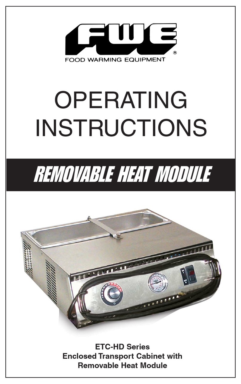
FWE PHU-12-CIN PROOFER User manual

PHU-12-CIN PROOFER
OPERATING
INSTRUCTIONS
PHU-12-CIN
ORIGINAL INSTRUCTIONS
Caution: Read the
instructions before
using the machine.
INTERNATIONAL

WARNING SYMBOLS
To indicate hazards arising from dangerous
voltages
To identify the terminals which, when connected
together, bring the various parts of an equipment or of a
system to the same potential.
To identify the terminal which is intended for
connection to an external conductor for protection against
electric shock in case of a fault, or the terminal of a protec-
tive earth (ground) electrode
To indicate that the marked item can be hot and should not
be touched without taking care
To indicate the “ON” condition for a part of
equipment
To indicate the “OFF” condition for a part of
equipment
To indicate the stand-by or preparatory state for a part of
equipment
To indicate maximum ll level
To indicate minimum water level
To indicate moisture settings
To indicate heat settings
WARNING SYMBOLS AND EXPLANATIONS
FWE PHU-12-CIN PROOFER
2FWE PHU-12-CIN PROOFER *Symbols will vary from unit to unit.

3
CASTER DESCRIPTION
2” GREY RUBBER CASTER,SWIVEL W/BRK
CASTER 2” RIGID
CASTER 3” RIGID
CASTER 3.5” RIGID HEAVY DUTY
CASTER 4X2” EZ ROLL RIGID POLYBLUE
CASTER 5” RIGID HEAVY DUTY
CASTER 5” RIGID SUPER DUTY
CASTER 5” SWIVEL BRAKE RB GRS FIT Poly
CASTER 5” RIGID EZ ROLL POLY
CASTER 5” SWIVEL BRAKE EZ ROLL POLY
CASTER 6” RIGID HEAVY DUTY
CASTER 6” RIGID SUPER DUTY
CASTER 6” SWIVEL BRAKE EZ ROLL POLY
CASTER 6” RIGID EZ ROLL POLY
CASTER 8” PNEUMATIC RIGID
CASTER 8” RIGID HEAVY DUTY
CASTER 8” RIGID SUPER DUTY
CASTER 8” SWIVEL BRAKE EZ ROLL POLY
CASTER 8” RIGID EZ ROLL POLY
MAX WEIGHT
34Kg
68Kg
68Kg
113Kg
272Kg
124Kg
226Kg
340Kg
362Kg
362Kg
158Kg
272Kg
453Kg
453Kg
113Kg
226Kg
272Kg
544Kg
544Kg
IN THE EVENT OF ACCIDENT OR
BREAKDOWN - UNPLUG UNIT.
FOR SERVICE INQUIRIES PLEASE CALL
FWE SERVICE - 800-222-4393
Improper use of this machine can result in injury and/or death.
A schedule should be put in place for inspections and
preventative maintenance.
New users should be properly trained in the use of this
equipment.
No special protective equipment is required to operate
this unit.
Unplug unit before servicing.
CASTER WEIGHT CHART AND SERVICE INFORMATION
FWE PHU-12-CIN PROOFER
SEE SHIPPING LABEL FOR CASTER SIZE

Keep your cabinet clean by simply wiping the interior and
exterior, as needed, with a damp cloth or sponge and a mild
soapy solution.
NEVER USE ABRASIVES, ACIDS, OR STRONG
CLEANERS.
Do not flood or allow electrical parts to become wet. The
interior tray slide assemblies and humidifier pans are
removable for easy cleaning.
A stainless steel cleaner/polish is recommended for the
exterior to maintain a “like-new” appearance.
DO NOT USE WAX OR STRONG CLEANERS ON DOOR
GASKETS OR VINYL TRIM.
12″x 20″(305mm x 508mm) pan is
removable and replaceable for
easy cleaning.
12″x 20″ (305mm x 508mm) pan cor-
rectly positioned in
HEAT BASIN.
Heat
Tunnel
positions
into
tabs.
Heat
Tunnel
CLEANING
WARNING AND CLEANING CARE
FWE PHU-12-CIN PROOFER
4FWE PHU-12-CIN PROOFER

For U.S. and Canada Models:
The amperage of your cabinet is stamped on the name plate
serial tag attached to the unit. FWE models are equipped with
a grounded cord plug for your protection against possible shock
hazards. Be sure to plug only into a properly grounded wall
receptacle. If you have any questions with regard to adequate
wiring or grounding in your building, a qualified electrician should
be contacted before using your cabinet.
For International Models:
May be shipped with no cord or plug
Contact qualified service personnel for cord and plug
installation.
DO NOT, UNDER ANY CIRCUMSTANCES, CUT OR REMOVE
THE GROUNDING PRONG FROM THE
CORD PLUG.
WARNING: ONLY A QUALIFIED SERVICE PERSONNEL
WILL REMOVE, REPAIR OR REPLACE ELECTRICAL
COMPONENTS OR WIRING.
BE SURE THAT MODEL IS UNPLUGGED FROM ELECTRICAL
SOURCE BEFORE REMOVING
CONTROL PANEL, MOVING, CLEANING, OR SERVICING
UNIT.
ELECTRICAL REQUIREMENTS AND GROUNDING
5
FWE PHU-12-CIN PROOFER
WARNING AND CLEANING CARE
INTENDED USE AND REQUIREMENTS
This unit is to be used for proofing and warming only.
Unit must be installed level.

Cord Winding
Bracket
Control Panel
Serial Tag
and
Parts List
Heat System
Tunnel
12″ x 20″
(305mm x 508mm)
Water Pan
and
Heat Basin
Removable
Drip Pan
Moisture Drip
Trough with
Removable
Drain Plug
PHU-12-CIN PROOFER
6FWE PHU-12-CIN PROOFER

CONTROL PANEL
FWE PHU-12-CIN PROOFER
7
Heat Cycling Light
Thermometer
Air Temperature
“HEAT”
Control Dial
Press tactile key to
alternate between
ACTUAL temp
(with ACTUAL LED
illuminated) and
SETPOINT temperature.
° F to°C Temp Units
1. Turn “HEAT” knob
to OFF and turn rocker
switch OFF.
2. Turn rocker switch ON
while pressing the “TEMP
RECALL”. Repeat to
toggle from °F to °C
Air Moisture Control Dial
Proof
Proof Cycling Light
Main Power
Rocker Switch
Recommended
Settings:
AIR TEMPERATURE
SETTING:
110°F / 43°C
PROOF SETTING
:5
Low Temp Alarm

8FWE PHU-12-CIN PROOFER
FWE PHU-12-CIN PROOFER
ENABLING ALARMS
LOW TEMP ALARM OPERATION
Unit has a built in “Low Temp Alarm”, allowing the operator to have
an audible and a visual indicator that the heated cabinet
temperature falls below the "Low Temperature" set point for more
than two (2) minutes.
1) Adjust Set Point: Press and hold “Low Temp Alarm” for six (6)
seconds. Rotate dial to desired set point between “ " and from
90°F (32°C) and 190°F (88°C). Display will beep and show "LTA"
for two (2) seconds release button to accept adjustment. When the
internal cabinet temperature falls below the desired "Set Point" for
more than two (2) minutes, the audible and visual alarm will alert
you to this condition.
2) Recall Set Point: Press "LOW TEMP ALARM" key.
Display shows LTA set point for three seconds then reverts to
normal display.
3) Acknowledge: Press any key to cancel beeping
For Every ten (10) seconds, the display will show LTA for one (1)
second until temperature increases above LTA set point.
Note: The Low Temp alarm will auto-reset once Oven Setpoint is
reached again. The idea is if the user has perhaps left the door
open, the LTA alarm sounds to remind them to close it, with the user
pressing either key to stop the beeping. Once the door is closed and
the oven temperature rises again to oven setpoint, the control
re-enables the LTA alarm in case the user fails to close the door
again.
4) Disable: Follow the adjustment steps above.
A rotation of the dial "down" below 90°F (32°C) turns the alarm
feature off.

INSTALLATION
FWE PHU-12-CIN PROOFER
9
CONGRATULATIONS...
...and thank you for purchasing an FWE PHU-12-CIN Proofer.
Your unit has been designed and manufactured under rigid
controls to assure you the most efficient service. It is a full time
unit, and may be used continuously.
Please take a moment to read through this booklet of important
information pertaining to your cabinet. By following a routine of
proper use and care described on the following pages, your
cabinet will last for many years.
IMPORTANT: Your Manufacturer Registration Card must be
returned within 30 days after initial delivery to activate the
warranty.
These numbers are found on the nameplate (serial tag) affixed
near the electrical cord portal. Please record them in this
booklet, in the space provided on page 14. When calling in
regards to service, you will need to provide this information.
The voltage and amperage of the unit are also stamped
on the serial tag.
SERIAL AND MODEL NUMBER
UNPACKING
After uncrating your cabinet, remove all tape and padding which
held all doors, shelves, racks, cord, etc., in place
during shipment.

FWE PHU-12-CIN PROOFER
GENERAL OPERATING INSTRUCTIONS
1) PLUG CABINET INTO A PROPERLY GROUNDED POWER
RECEPTACLE. Press the “ / ” rocker switch to the “ ” position.
2) ADD HOT WATER TO THE
12″x 20″(305MM X 508MM)
PAN. The 12″ x 20″
(305mm x 508mm) water
pan is positioned in the
heat basin. Do not allow any
water into the heat basin.
Add hot water into the
12″ x 20″ (305mm x 508mm) pan
prior to heating the cabinet.
This will allow the heating
system to condition cabinet and
add humidity.
It is not necessary to remove the pan to add water. Amount of water
required depends on start-up time, length of proofing and level of
humidity desired. DO NOT FILL ABOVE
3) PRE-HEAT THE CABINET. Turn on the rocker switch to the “ ”
position. Allow approximately 20-30 minutes of pre-heat time. The door
should be kept tightly closed during this procedure to obtain the
optimum environment.
For proofing, set the air temperature to 110°F (43°C).
4) SET AIR MOISTURE CONTROL to desired setting. The
“MOISTURE CYCLE” indicator light will illuminate when the element or
cycle is “ .”
NOTE: As with all proofing cabinets, your results may vary, depending
on room temperature and conditions, pre-heat time, temperature of
product going into the cabinet, etc.
5) LOAD THE CABINET with your product as quickly as possible. To
maintain the best conditions, the door should be tightly closed when not
loading the cabinet, and remain closed until serving.
AVOID PUTTING YOUR HOT FOODS INTO A COLD CABINET!
PREPARING THE CABINET BEFORE LOADING FOOD
10 FWE PHU-12-CIN PROOFER

The / rocker switch activates power to the Control.
PHU-12-CIN is equipped with two (2) heating elements and two (2)
separate controls which regulate these elements. This allows you to
adjust the temperature and humidity separately.
The air moisture knob adjusts the amount of humidity in the cabinet
from 1-6.
A CYCLING light indicates that this function is activated. The air
temperature control goes from 90°F to 130°F (30°C to 54°C), and
adjusts the amount of heat in the cabinet.
Use approximate setting: 110°F or 43°C.
An operational range thermometer shows the actual internal
temperature of the cabinet.
Add HOT water to 12" x 20" (305mm x 508mm) pan with heat tunnel
in position. Water Pan is positioned into heat basin.
FWE PHU-12-CIN PROOFER
11
FWE PHU-12-CIN PROOFER
EASY TO OPERATE
Water Pan
Heat Basin
PREPARING THE CABINET BEFORE LOADING FOOD

12 FWE PHU-12-CIN PROOFER
FWE PHU-12-CIN PROOFER
HEAT SYSTEM AND CABINET COMPONENTS
Add hot water to 12″ x 20″ (305mm x 508mm) pan with heat
tunnel in position. Water pan is positioned into heat basin.
Use caution when filling if heat tunnel is hot.
ADDING WATER TO 12″x 20″(305MM x 508MM) PAN
WARNING: THE WATER PAN, AIR TUNNEL AND HEATING
ELEMENT(S) ARE HOT WHEN IN USE AND COULD CAUSE INJURY.
Amount of water required in the pan is determine by
start-up time, length of holding time, and the level of
humidity desired.
HEAT BASIN shown
WITHOUT 12″x 20″
(305mm x508mm) pan.
KEEP HEAT
BASIN DRY
WATER PAN
POSITIONS INTO
HEAT BASIN.
ADD WATER INTO
12″x 20″
(305mm x508mm)
PAN
ONLY.
NO WATER IN
HEAT BASIN
Add
HOT WATER
to
12″x 20″
(305mm x
508mm)
Pan
Heat
Tunnel
TOP LINE
12″x 20″
(305mm x
508mm)
Pan
Positioned
Into
Heat Basin
BOTTOM LINE

DRIP TROUGH: DRAIN AS REQUIRED
A DRIP TROUGH has been provided to collect
excess cabinet moisture or run-off. It is located be-
low the door. Drain as often as required.
CAUTION:
Drain responsibly to keep area and oor
dry and safe.
FWE PHU-12-CIN PROOFER
DRAIN DRIP TROUGH
13

Model Number ______________________
Serial Number ______________________
Date of Purchase ____________________
Notes:
___________________________________________________
___________________________________________________
___________________________________________________
___________________________________________________
___________________________________________________
___________________________________________________
___________________________________________________
___________________________________________________
___________________________________________________
___________________________________________________
___________________________________________________
___________________________________________________
___________________________________________________
___________________________________________________
___________________________________________________
___________________________________________________
___________________________________________________
___________________________________________________
___________________________________________________
___________________________________________________
___________________________________________________
___________________________________________________
CAUTION: HOLDING FOOD AT TEMPERATURES
OF LESS THAN 140°F (60°C) MAY BE DANGEROUS.
TEMPERATURES UNDER 140°F (60°C) PROMOTE THE GROWTH
OF HARMFUL BACTERIA AND TOXINS IN SOME FOODS.
FWE PHU-12-CIN PROOFER
NOTES
14 FWE PHU-12-CIN PROOFER

FWE / Food Warming Equipment Company, Inc. (Seller) warrants to the original purchaser,
subject to the exceptions and conditions below, that FWE manufactured equipment shall be
free from defects in material or factory workmanship, under ordinary use for the purpose for
which it is designed. The effective warranty period is as follows:
PARTS: Seller will furnish without charge to the original purchaser, FOB Sellers’ factory,
replacement parts for repairs to all new standard catalog products and factory custom /
modified units, which in Seller’s sole judgment, prove defective in materials or workmanship
under normal and proper use with the reserved right to request the return of any part claimed
to be defective, prior to issuing replacement part or authorizing warranty service, for a period
of two (2) years from date of original shipment from Seller’s plant, except for equipment used
in a Correctional Environment / Facilities, which is warranted for a period of one (1) year
from date of original shipment from Seller’s plant.
LABOR: Seller’s labor warranty shall be performed by a Seller-approved Service Agency
who must contact Seller to obtain a Warranty Service Authorization (WSA) number prior to
performing any repairs. If service is required during overtime periods, the difference between
overtime and standard labor rates shall be paid by the purchaser. Seller does not assume any
responsibility for any charges not expressly authorized, incidental to the repair or replacement
of equipment covered by this warranty, nor charges exceeding, in Sellers sole judgment,
normal and customary amounts. Only approved travel charges will be allowed. Seller’s labor
warranty shall be from the date of original shipment date from Seller’s plant for a period of
one (1) year, except for equipment used in a Correctional Environment / Facilities which is
warranted for a period of six (6) months.
This warranty is for normal usage and does not apply to any product or parts thereof that
have been misused, altered, or where Seller’s operating instructions or specific voltage is not
observed; nor shall this warranty apply to defective products or parts resulting from accident
following date of original shipment, nor extend to or cover removal, installation, re-installation
or calibration, or service calls or cost of repairs undertaken by a customer. This warranty is
also subject to the following:
1.] Customer returning the warranty registration card, accompanying Sellers original
shipment, to Seller within thirty (30) days of receipt;
2.] Giving immediate notice of any allegedly defective part or product to Seller; and
3.] Customer, at Sellers request, returning said defective parts or product to Seller.
This is the sole warranty applicable to the merchandise. It is expressly understood that Seller’s
liability hereunder is limited to the repair or replacement, at Seller’s option, of products or parts,
defective materials or workmanship as provided above. Seller’s judgment as to the cause and
nature of any defect will be final. Seller shall in no case be responsible for special or
consequential damages or any other obligation or liability with respect to products sold by
Seller.
This warranty, as stated above, applies to equipment installed in the Continental United
States. FWE equipment installed outside the Continental United States shall carry parts
coverage only. All labor costs are approved on a discretionary basis, based on like repairs
in the Continental U.S. This warranty shall stand in whole or in part as allowed by law. Any
exclusion of a part of this warranty, as may be allowed by law, shall not void balance of
warranty.
This is a limited warranty pursuant to the Consumer Product Warranties Act, 15 U.S. Code. section 2303.
© 2003 Food Warming Equipment Co., Inc.
LIMITED TWO YEAR WARRANTY
FWE PHU-12-CIN PROOFER
15

© 2015 Food Warming Equipment Co., Inc. Errors subject to correction. All specifications subject to change without notice. Printed in USA.
Ops-Manual-PHU-12-CIN Proofer R.15.2
FWE Parts Department:
www.FWEparts.com
Order Hotline: 800-222-4393
FOOD WARMING EQUIPMENT COMPANY, INC.
COOK |HOLD |TRANSPORT |SERVE |REFRIGERATION |BARS
5599 HWY. 31 W. Portland, TN 37148
800.222.4393 |815.459.7500 |Fax: 815.459.7989
Table of contents
Other FWE Commercial Food Equipment manuals
FWE
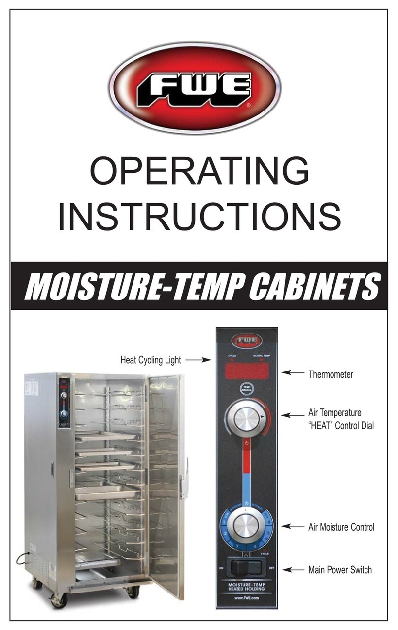
FWE PHU Series User manual

FWE
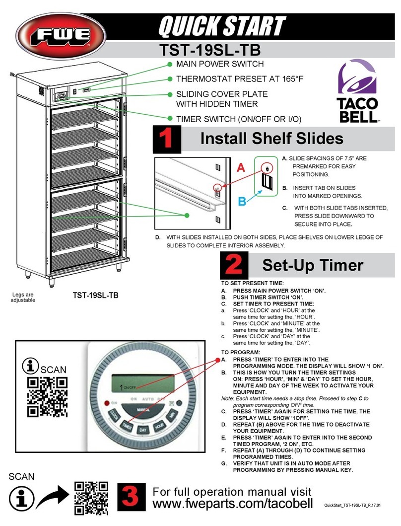
FWE TACO BELL TST-19SL-TB User manual

FWE
FWE PST-32 User manual

FWE
FWE R-AS-10 Operating instructions

FWE
FWE HLC Series User manual

FWE
FWE ETC-HD Series User manual

FWE
FWE ETC Series User manual
FWE
FWE HLC-1717 Series User manual

FWE
FWE E Series User manual

FWE
FWE COMBI-COMPANION LCH-CC Series User manual

Popular Commercial Food Equipment manuals by other brands

Fanset
Fanset Fantom PROCART 250 Assembly manual

Vollrath
Vollrath STOELTING Flavor Burst STL-80BLD Operator's manual

Blodgett
Blodgett BLT-E Series Installation operation & maintenance

EVEREST REFRIGERATION
EVEREST REFRIGERATION ECB36D2 owner's manual

Gastrodomus
Gastrodomus GAL4100TN user manual

Tecnoinox
Tecnoinox BM4E9 Installation, use and maintenance