FXA FXA92502 User manual

FXA92502
Instruction manual (Original instructions) GB pg 9-19
Käyttöohje (Alkuperäisten ohjeiden käännös) FI pg 20-30
Bruksanvisning (Översättning av originalinstruktionerna) SE pg 31-41
Bruksanvisning (Oversettelse av de opprinnelige instruksjonene) NO pg 42-52
Руководство пользователя (Перевод исходных инструкций) RU pg 53-65
Kasutusjuhend (Tõlgitud originaal juhendist) EE pg 66-77
Instrukcijas (Tulkojums no oriģinālvalodas) V pg 78-88
Instaliavimo instrukcijos (Vertimas originali instrukcija) T pg 89-99

2
12
1
23
11
10
9
837 6
5
4
(1)

3
26
27
13
18
17
16
15
14
19
25
24
22
23
21 20
(1A)

4
35
28
47
29
30
34
33
32
31
(1B)

5
46
36 37 38 39 40 41
42
45
44
43
(1C)

6
(A) (C)(B)
(D) (F)(E)
( ) (I)
PRESS
(H)
(J) (L)
PRESS
(K)
21
22
36
37 712
22
21
19 22
35
22
19
112
14
19 3-5mm 14
3
1
10
12
27
8
426
25
6
518
24
17
15
16

7
(M) (O)(N)
(P) (S)
PRESS
(R)
(T) (W)(U)
(X) (Z)(Y)
12
11 48
28
45
46
5mm
29
31
32
4
25
26
25
26
c
14
33
47 a
44
43
40
42
39
b
6
48

8
IMPORTANT! Read all safety warnings, instructions, illustrations and specifications provided with this
power tool.
TÄRKEÄÄ! Lue tarkkaavaisesti kaikki tämän työkalun kanssa toimitetut varoitukset, ohjeet ja
spesifikaatiot, ja katso lisäksi kuvat.
VIKTIGT! Läs uppmärksamt alla varningar, instruktioner och specifikationer som bifogas med
detta verktyg och studera bilderna.
VIKTIG! Les nøye gjennom alle advarslene, instruksene og spesifikasjonene som følger med
verktøyet, og se på tegningene.
ВАЖНО! Пpoчтитe вce yкaзaния, инcтpyкции, иллюcтpaции и cпeцификaции, поставляемые
c электроинструментом.
TÄHTIS! Lugege läbi kõik elektrilise tööriista kohta esitatud ohuhoiatused ning tutvuge
tööriista jooniste ja tehniliste andmetega.
SVARĪGI! Izlasiet visus drošības brīdinājumus, instrukcijas, specifikācijas un apskatiet attēlus šī
elektroinstrumenta dokumentācijā.
SVARBU! Perskaitykite visus saugos įspėjimus, visas instrukcijas, paveikslėlius ir techninius
reikalavimus, pateikiamus su šiuo elektriniu įrankiu.

9
INTRODUCTION
Thankyou for purchasing this product which has
passed through our extensive quality assurance
process. Every care has been taken to ensure that it
reaches you in perfect condition.
SAFETY FIRST
Before attempting to operate this power tool the
following basic safety precautions should always be
taken to reduce the risk of fire, electric shock and
personal injury. It is important to read the instruction
manual to understand the application, limitations and
potential hazards associated with this tool.
CERTIFICATE OF GUARANTEE
This product is guaranteed for a period of 2 Years,
with effect from the date of purchase and applies only
to the original purchaser. This guarantee only applies
to defects arising from, defective materials and or
faulty workmanship that become evident during the
guarantee period only and does not include
consumable items. The manufacturer will repair or
replace the product at their discretion subject to the
following. That the product has been used in
accordance with the guide lines as detailed in the
product manual and that it has not been
subjected to misuse, abuse or used for a purpose for
which it was not intended. That it has not been taken
apart or tampered with in any way whatsoever or has
been serviced by unauthorised persons or has been
used for hire purposes. Transit damage is excluded
from this guarantee, for such damage the transport
company is responsible. Claims made under this
guarantee must be made in the first instance, directly
to the retailer within the guarantee period. Only under
exceptional circumstances should the product be
returned to the manufacturer. In these case it shall be
the consumer’s responsibility to return the product at
their cost ensuring that the product is adequately
packed to prevent transit damage and must be
accompanied with a brief description of the fault and
a copy of the receipt or other proof of purchase. The
manufacturer shall not be liable for any special,
exemplary, direct, indirect, incidental, or consequential
loss or damage under this guarantee. This guarantee
is in addition to and does not affect any rights, which
the consumer may have by virtue of the Sale of oods
Act 1973 as amended 1975 and 1999.
STATUTORY RIGHTS
This guarantee is in addition to and in no way affects
your statutory rights.
PRODUCT DISPOSA
When this product reaches the end of it’s life or is
disposed of for any other reason, it must not be
disposed of in household waste. In order to preserve
natural resources, and to minimise adverse
environmental impact, please recycle or dispose of
this product in an environmentally friendly way. It
should be taken to your local waste recycling centre
or other authorised collection and disposal facility.
If in doubt consult your local waste authority for
information regarding available recycling and / or
disposal options.
GENERA SAFETY RU ES
WARNIN ! Read all instructions Failure to follow all
instructions listed below may result in electric shock,
fire and/or serious injury. The term "power tool" in all
of the warnings listed below refers to your mains
operated (corded) power tool or battery operated
(cordless) power tool.
SAVE THESE INSTRUCTIONS
1) WORK AREA
a) Keep work area clean and well lit. Cluttered and
dark areas invite accidents.
b) Do not operate power tools in explosive
atmospheres, such as in the presence of
flammable liquids, gases or dust. Power tools
create sparks which may ignite the dust or fumes.
c) Keep children and bystanders away while
operating a power tool. Distractions can cause
you to lose control.
2) E ECTRICA SAFETY
a) Power tool plugs must match the outlet. Never
modify the plug in any way. Do not use any
adapter plugs with earthed (grounded) power
tools. Unmodified plugs and matching outlets will
reduce risk of electric shock.
b) Avoid body contact with earthed or grounded
surfaces such as pipes, radiators, ranges and
refrigerators.
There is an increased risk of electric shock if your
body is earthed or grounded.
c) Do not expose power tools to rain or wet
conditions. Water entering a power tool will
increase the risk of electric shock.
d) Do not abuse the cord. Never use the cord for
carrying, pulling or unplugging the power tool.
Keep cord away from heat, oil, sharp edges or
moving parts. Damaged or entangled cords
increase the risk of electric shock.
e) When operating a power tool outdoors, use an
extension cord suitable for outdoor use. Use of
a cord suitable for outdoor use reduces the risk of
electric shock.
3) PERSONA SAFETY
a) Stay alert, watch what you are doing and use
common sense when operating a power tool.
Do not use a power tool while you are tired or
under the influence of drugs, alcohol or
medication. A moment of inattention while
operating power tools may result in serious
personal injury.

10
b) Use safety equipment. Always wear eye
protection. Safety equipment such as dust mask,
non-skid safety shoes, hard hat, or hearing
protection used for appropriate conditions will
reduce personal injuries.
c)Avoid accidental starting. Ensure the switch is in
the off position before plugging in. Carrying
power tools with your finger on the switch or
plugging in power tools that have the switch on
invites accidents.
d)Remove any adjusting key or wrench before
turning the power tool on.
Awrench or a key left attached to a rotating part of
the power tool may result in personal injury.
e) Do not overreach. Keep proper footing and
balance at all times. This enables better control of
the power tool in unexpected situations.
f) Dress properly. Do not wear loose clothing or
jewellery. Keep your hair, clothing and gloves
away from moving parts. Loose clothes, jewellery
or long hair can be caught in moving parts.
g) If devices are provided for the connection of
dust extraction and collection facilities, ensure
these are connected and properly used. Use of
these devices can reduce dust related hazards.
4) POWER TOO USE AND CARE
a) Do not force the power tool. Use the correct
power tool for your application. The correct
power tool will do the job better and safer at the
rate for which it was designed.
b) Do not use the power tool if the switch does not
turn it on and off. Any power tool that cannot be
controlled with the switch is dangerous and must
be repaired.
c) Disconnect the plug from the power source
before making any adjustments, changing
accessories, or storing power tools. Such
preventive safety measures reduce the risk of
starting the power tool accidentally.
d) Store idle power tools out of the reach of
children and do not allow persons unfamiliar
with the power tool or these instructions to
operate the power tool. Power tools are
dangerous in the hands of untrained users.
e) Maintain power tools. Check for misalignment or
binding of moving parts, breakage of parts and
any other condition that may affect the power
tools operation. If damaged, have the power tool
repaired before use. Many accidents are caused
by poorly maintained power tools.
f) Keep cutting tools sharp and clean. Properly
maintained cutting tools with sharp cutting edges
are less likely to bind and are easier to control.
g) Use the power tool, accessories and tool bits
etc., in accordance with these instructions and
in the manner intended for the particular type of
power tool, taking into account the working
conditions and the work to be performed. Use of
the power tool for operations different from
intended could result in a hazardous situation.
5) SERVICE
a) Have your power tool serviced by a qualified
repair person using only identical replacement
parts. This will ensure that the safety of the power
tool is maintained.
ADDITIONA SAFETY RU ES FOR TOO
For both mitre saw mode and table saw (bench
saw) mode:
1 Wear eye and hearing protection. Other suitable
personal protective equipment should be worn.
2 NEVER wear gloves during operation except for
replacing saw blades or handling rough material
before operation.
3 Keep the floor area around the tool level well
maintained and free of loose materials e.g. chips
and cut-offs.
4 Do not operate saw without guards and riving
knife in place. Check blade guards for proper
closing before each use. Do not operate saw if
blade guards do not move freely and close
instantly. Never clamp or tie the blade guards into
the open position. Any irregular operation of the
blade guards should be corrected immediately.
5 Clean and be careful not to damage the spindle,
flanges (especially the installing surface) and hex
bolt before or when installing the blade. Damage
to these parts could result in blade breakage.
Poor installation may cause vibration/ wobbling
or slippage of the blade. Use only flanges
specified for this tool.
6 Check the blade carefully for cracks or damage
before operation. Do not use saw blade which are
damaged or deformed.
7 Use only saw blades recommended by the
manufacturer and which conform to EN847-1,
and observe that the riving knife must not be
thicker than the width of the cut by the saw blade
and not thinner than the body of the blade.
8 Always use accessories recommended in this
manual. Use of improper accessories such as
abrasive cut-off wheels may cause an injury.
9 Select the correct saw blade for the material
to be cut.
10 Do not use saw blades manufactured from high
speed steel.

11
11 To reduce the emitted noise, always be sure that
the blade is sharp and clean.
12 Use correctly sharpened saw blades. Observe the
maximum speed marked on the saw blade.
13 Do not cut metals such as nails and screws.
Inspect for and remove all nails, screws and other
foreign matter from the work piece before
operation.
14 Knock out any loose knots from work piece
BEFORE beginning to cut.
15 Don’t use the tool in the presence of flammable
liquids or gases.
16 For your safety, remove the chips, small pieces,
etc. from the work area and table top before
plugging the tool and starting operation.
17 The operator is adequately trained in the use,
adjustment and operation of the tool.
18 Keep hands and make your bystander and
yourself position out of path of and not in line
with saw blade. Avoid contact with any coasting
blade. It can still cause severe injury and never
reach around saw blade.
19 Be alert at all times, especially during repetitive,
monotonous operations. Don’t be lulled into a
false sense of security. Blades are extremely
unforgiving.
20 Make sure the shaft lock is released before the
switch is turned on.
21 Before using the tool on an actual work piece, let
it run for a while. Watch for vibration or wobbling
that could indicate poor installation or a poorly
balanced blade.
22 Wait until the blade attains full speed before
cutting.
23 The tool should not be used for slotting,
rabbetting or grooving.
24 Refrain from removing any cut-offs or other parts
of the work piece from the cutting area whilst the
tool is running and the saw head is not in the rest
position.
25 Stop operation immediately if you notice anything
abnormal.
26 Turn off tool and wait for saw blade to stop
before moving work piece or changing settings.
27 Unplug tool before changing blade, servicing or
not in use.
28 Some dust created from operation contains
chemicals known to cause cancer, birth defects
or other reproductive harm. Some examples of
these chemicals are:
-lead from lead-based-painted material and,
-arsenic and chromium from chemically treated
lumber.
Your risk from these exposures varies, depending
on how often you do this type of work. To reduce
your exposure to these chemicals: work in a well-
ventilated area and work with approved safety
equipment, such as those dust masks that are
specially designed to filter out microscopic
particles.
29 Connect the tool to a dust collecting device when
sawing.
30 Make sure that the table is securely fixed with the
lever after turning it over.
CAUTION
imitations on ambient conditions: < 40°C
When using in mitre saw mode:
31 Do not use the saw to cut other than wood,
aluminium or similar materials.
32 Do not perform operation freehand when cutting
work piece in an area close to saw blade. The
work piece must be secured firmly against the
turntable and guide fence during all operations.
33 Make sure that the turntable is properly secured
so it will not move during operation.
34 Make sure that the arm is securely fixed when
bevelling. Tighten the lever clockwise to fix the
arm.
35 Make sure the blade does not contact the
turntable in the lowest position and is not
contacting the work piece before the switch is
turned on.
36 Hold the handle firmly. Be aware that the saw
moves up or down slightly during start-up and
stopping.
When using in the table saw (bench saw) mode:
37 Do not perform any operation freehand.
Freehand means using your hands to support or
guide the work piece, in lieu of a rip fence.
38 Make sure that the turntable is fixed securely.
39 Make sure that the arm is securely fixed in the
working position. Tighten the lever clockwise to
fix the arm.
40 Use a push stick or a push block to avoid
working with the hands and fingers close to the
saw blade.
41 Make sure the blade is not contacting the riving
knife or work piece before the switch is turned
on.

12
42 Always store the push-stick when it is not in use.
43 Pay particular attention to instructions for
reducing risk of KICKBACK. KICKBACK is a
sudden reaction to a pinched, bound or
misaligned saw blade. KICKBACK causes the
ejection of the work piece from the tool back
towards the operator.
KICKBACKS CAN LEAD TO SERIOUS
PERSONAL INJURY. Avoid KICKBACKS by
keeping the blade sharp, by keeping the rip
fence parallel to the blade, by keeping the riving
knife and blade guard in place and operating
properly, by not releasing the work piece until you
have pushed it all the way past the blade, and by
not ripping a work piece that is twisted or warped
or does not have a straight edge to guide along
the fence.
44 Avoid abrupt, fast feeding. Feed as slowly as
possible when cutting hard work pieces. Do not
bend or twist work piece while feeding. If you stall
or jam the blade in the work piece, turn the tool
off immediately. Unplug the tool. Then clear the
jam.
45 Before turning over the tool, always make sure
that the stopper pin has securely locked the tool
head in the lowest position.
1. Riving knife
2. Fixing pin for cutting blade shield
3. Cutting blade shield
4. Locking button for cutting blade tilt lever
5. Cutting blade lift/lower knob
6. Locking lever for cutting blade tilt
7. Cutting blade bottom shield
8. Switch
9. Power cord holder
10. Ripping fence fixing screw
11. Work table rotation locking lever
12. Work table
13. Ripping fence
14. Cutting blade
15. Crosscut fence
16. Crosscut fence fixing knob
17. Locking knob of the mitre gauge
18. Mitre gauge
19. Wheel
20. Holder for push stick
21. Leg locking knob
22. Leg
23. Adjustable foot
24. Mitre gauge slot
25. Angle scale for cutting blade tilt
26. Cutting blade tilt indicator
27. Ripping fence fixing knob
28. Head locking pin
29. Table rotation locking knob
30. Fence
31. Turntable
32. Angle scale of turntable
33. Carbon brush cover
34. Movable shield
35. Riving knife fixing knob
36. Dust bag
37. Dust extraction outlet
38. Stationary shield
39. Movable shield locking lever
40. Switch lock button
41. Handle grip
42. Switch
43. Vertical clamp locking knob
44. Vertical clamp
45. Vertical clamp locking lever
46. Head position locking lever
47. Limiter
48. Spindle lock lever
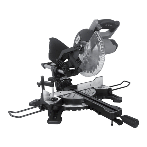
COMPONENTS & CONTRO S (FIG.1 TO 1C)
TAB E SAW ITEMS MITRE SAW ITEMS
* Differences may appear between the product
and drawing.

13
UNPACKING
Caution! This packaging contains sharp objects. Take
care when unpacking. Remove the machine, together
with the accessories supplied, from the packaging.
Check carefully to ensure that the machine is in good
condition and account for all the accessories listed in
this manual. Also make sure that all the accessories
are complete. If any parts are found to be missing, the
machine and its accessories should be returned
together in their original packaging to the retailer.
Do not throw the packaging away, keep it safe
throughout the guarantee period, then recycle if
possible, otherwise dispose of it by the proper means.
Do not let children play with empty plastic bags due
to the risk of suffocation.
ASSEMB Y
Note: Before carrying out any assembly or
disassembly of the unit please ensure that the unit is
not connected to the electrical supply.
CAUTION: Keep the floor area around the tool level
well maintained and free of loose materials such as
chips and cut-offs.
F IP OVER SAW ASSEMB Y (FIG. A)
Tilt the saw slightly to the side. Use the screws and
leg locking knobs (21) (included) to attach the legs (22)
to the base.
Set up the adjustable feet (23) so the flip over saw
stands firmly.
DUST EXTRACTION (FIG. B)
To install the dust bag (36) slide it firmly onto the dust
extraction outlet (37) (when operating in mitre saw
mode). To empty the dust bag (36), remove it from the
dust extraction outlet (37) and open the zipfastener
that allows to access inside the bag. Whenever more
efficient dust extraction is required especially for
health hazardous carcinogenic dusts, attach hose of
suction device directly to the dust extraction outlet
(37) (when using in table saw mode) or outlet in the
cutting blade bottom shield (7) (when using in mitre
saw mode).
Note: Empty the dust bag on a regular basis. To
achieve optimal dust extraction empty the bag when it
is 2/3 full.
INSTA ATION OF THE CUTTING B ADE BOTTOM
SHIE D (FIG. C)
When in mitre saw mode, the cutting blade bottom
shield must be installed to cover lower part of the
cutting blade.
Install the cutting blade bottom shield (7) and fasten
with screws.
Remove the cutting blade bottom shield (7) before
operating in table saw mode.
TRANSPORTATION (FIG. D & E)
Before moving the tool follow the procedure:
Set up the tool in table saw mode.
Remove the ripping fence (13) and the mitre gauge
(14).
Install the cutting blade bottom shield (7).
Tilt the saw slightly to the side.
Loosen the leg locking knobs (21) at the wheels (19),
turn the legs (22) inside by 90º (along the saw) and
lock in this position with the leg locking knobs (21).
Do the same with the second pair of legs (22) and turn
them by 90º outside of the tool (Fig. D).
Turn the saw so it stands on the wheels, hold the legs
(22) with your both hands and roll the saw to another
location (Fig. E).
Follow the above described procedure in reverse
order to reassemble the tool to table saw mode or
mitre saw mode.
INSTA ING THE POWER CORD HO DERS
Attach the power cord holders (9) using the screws
provided. The position of the power cord holders can
be seen in Fig.1.
INSTA ING THE PUSH STICK HO DERS
Attach the push stick holders (20) using the screws
provided. The position of the power cord holders can
be seen in Fig.1A.
OPERATION & SETTINGS
Ensure the saw is disconnected from power supply
before making any adjustments. To ensure safe,
precise and efficient saw operation, proceed with all
adjustment procedures as a whole.
After finishing all the setting and adjustment
procedures ensure that all adjustment keys are
collected. Check that all joining elements are properly
fitted.
When making adjustments ensure that all external
parts work properly and conform with all conditions
necessary for proper operation. Any worn out or
damaged part must be replaced by qualified
personnel before starting to use the saw.
CUTTING RECOMMENDATIONS
It is recommended to make a test cut after each
adjustment to make sure the new settings are correct
and to check dimensions.
After switching the saw on, wait until cutting blade
reaches its top maximum speed while running idle
before making a cut.
Secure long objects from falling after cutting (e.g. with
a roller support).
Be very careful when starting a cut!
When cutting wood that has already been used,
ensure it is free from unwanted objects, such as nails,
screws etc.
Wait until cutting blade comes to a complete stop
before removing cut off pieces.

14
Always hold main part of the processed material.
Never hold the part that is being cut off.
TAB E SAW MODE
SETTING THE RIVING KNIFE (FIG. F)
Set the work table (12) to mitre saw position.
Put the blade into 0° cross-cut position.
Set the mitre saw to the highest position by releasing
the head locking pin (28) from the locking hole. Turn
the head locking pin 90º so it rests in the open
position.
Loosen the riving knife fixing knob (35) and turn the
riving knife (1) to position where it covers the cutting
blade (14), so the sleeve protrusions match the
guiding grooves. You must retract the blade guard
completely for the riving knife (1) to fit properly in
place. To retract the blade guard press the movable
shield locking lever (39). Be careful when retracting
the blade guard as the blade is shrp and can cause
injury.
Fasten the riving knife fixing knob (35) to fix in place.
Pull down the sawhead to it lowest position and turn
the cutting blade lift/lower knob (5) until the head
locking pin (28) can engage in the locking hole.
Pull the work table rotation locking lever (11) and turn
the work table (12) to position of table saw mode.
Note: Set the riving knife (1) so the distance between
the cutting blade (4) and the riving knife is between
3-5 mm (riving knife should be positioned exactly in
line with the cutting blade), Fig. . Check position of
the riving knife after each replacement of cutting
blade.
INSTA ING THE CUTTING B ADE SHIE D
(FIG. H)
Push in the button of the fixing pin for cutting blade
shield (2) and put the cutting blade shield (3) onto the
riving knife (1).
You can remove the cutting blade shield by following
above procedure in reverse sequence.
Note: Attach the cutting blade shield so it lifts as the
material is fed towards the cutting blade and freely
falls after the cutting is finished.
INSTA ING THE RIPPING FENCE (FIG. I)
The ripping fence can be installed on the work table
on either side of the cutting blade shield.
Slide the fixing of the ripping fence (13) into guide slot
in the work table (12).
Set up the ripping fence (13) in required position (use
the scale) and secure with the ripping fence fixing
knob (27).
It is recommended to make a test cut, measure and if
necessary readjust the ripping fence.
To prevent seizing of processed material you can
loosen the ripping fence fixing screw (10) and move
the ripping fence (13) lengthwise (Fig. I).
Note: Reposition the ripping fence fixing when
installing the ripping fence on the opposite side of the
work table.
SWITCHING ON AND OFF (FIG. J)
The mains voltage must match the voltage on the
rating plate of the saw.
Switch on the saw only when the processed material
is away from the cutting blade.
Switching On – press the button I of the switch (8) .
Switching Off – press the button O of the switch (8).
CUTTING DEPTH ADJUSTMENT
Turn the cutting blade lift/lower knob (5) counter-
clockwise or clockwise to increase or decrease
cutting depth.
Note: The saw should be adjusted so the highest
point of the cutting blade is just above the surface of
the material being cut.
BEVE CUTTING (FIG. K)
Always use the ripping fence when making a bevel
cut.
Loosen the locking lever for cutting blade tilt (6). (For
easy use you can press the locking button for cutting
blade tilt lever (4) and change position of the locking
lever for cutting blade tilt (6).)
Set the cutting blade (14) to maximum cutting depth.
Change position of the cutting blade (14) to obtain the
required angle shown by the cutting blade tilt indicator
(26) on the angle scale for cutting blade tilt (25).
Tighten the locking lever for cutting blade tilt (6).
Set the ripping fence (13) to required cutting width.
Switch on the saw and make a cut.
MITRE CUTTING WITH THE MITRE GAUGE (FIG. )
You can install mitre gauge in one of two guide slots
located on both sides of the work table.
Remove the ripping fence (13) from the work table top
(12).
Place the mitre gauge (18) in one of the mitre gauge
slots (24).
Use the crosscut fence fixing knob (16) to attach the
crosscut fence (15) to the mitre gauge (18), set up the
required cutting angle and secure it with the locking
knob of the mitre gauge (17) (Fig. L).
When tilting of the cutting blade is required for bevel
cutting, set the crosscut fence (15) so it cannot
contact the cutting blade (it is possible to move the
crosscut fence).

15
Before switching the saw on, move the mitre gauge
(18) towards cutting blade and ensure the crosscut
fence (15) is approximately 2 cm away from the
cutting blade.
Firmly push processed material against the crosscut
fence (15).
To make a cut, switch on the saw and move the mitre
gauge with the crosscut fence and processed material
towards the cutting blade.
Note: Always move the material being cut far enough
to complete the cutting.
When cross-cutting do not use ripping fence as a
length limiter for piece of material being cut off,
because this piece may jam between the ripping fence
and the cutting blade, and cause kick back effect.
RIPPING
Ripping is cutting the material to desired width along
its whole length.
Set the ripping fence (13) to the appropriate cutting
width.
Switch the saw on and wait until the cutting blade
reaches its full rotational speed.
Press the material against the ripping fence (13) and
move towards cutting blade to the end of the riving
knife (1) (use the push stick when close to the cutting
blade).
Leave the cut material on the work table until the
cutting blade stops completely.
Note: Make a test cut after each adjustment to make
sure the new setting is correct. When making a cut
stand to the side of the line of cutting.
CUTTING SMA OBJECTS
Set the ripping fence (13) to the appropriate cutting
width.
Feed the material with both hands. When getting
close to the cutting blade always use the push stick
(included) to move the material or use an additional
piece of wood to push the material being cut against
the ripping fence (13).
Always push the cut material to the end of the riving
knife (1).
Note: When cutting short and narrow objects, use the
push stick from the beginning.
MITRE SAW MODE
If the tool has not been used or has been used in
table saw mode, use the cutting blade lift/lower knob
to bring the cutting blade to the lowest position.
INSTA ATION (FIG. M)
Remove the cutting blade shield (3).
Bring the cutting blade (14) to the lowest position with
the cutting blade lift/lower knob (5).
Remove the ripping fence (13) and the mitre gauge
(18).
Install the cutting blade bottom shield (7).
Pull away the work table rotation locking lever (11)
and turn the work table (12) by 180º until you can
clearly hear the work table rotation locking lever (11)
snap into place (Fig. M).
Loosen the riving knife fixing knob (35) and turn the
riving knife (1) to a position where the cutting blade
(14) is uncovered, so the sleeve protrusions match the
guiding grooves.
Fasten the riving knife fixing knob (35) to fix in place.
USING THE SAW ARM (FIG. N)
There are two positions of the saw arm, upper and
lower. To release the head from the locked lower
position, do the following:
Press the saw arm lightly and hold.
Pull the head locking pin (28) away, so its safety bolt
slides out of the locking hole.
Turn the head locking pin (28) by 90º and lock in
position (Fig. N).
Hold the saw arm as it lifts to its upper position.
You can lock the saw arm in lower position by
following unlock procedure in reverse order after
releasing the movable shield locking lever (39).
INSTA ING THE VERTICA C AMP (FIG. O)
The vertical clamp can be installed at either side of
the work table and is fully adjustable to size of the
object to be cut.
Install the vertical clamp (44) into one of the holes in
the work table.
Tighten the vertical clamp locking knob (43).
Turn the threaded rod to match the vertical clamp (44)
with the processed material.
Secure by pressing the vertical clamp locking lever
(45) (Fig. O).
Note: Always fix the processed material in place to
guarantee optimal work safety. Do not cut objects too
small to fix in place.
ADJUSTING THE CUTTING DEPTH (FIG. N & P)
Before starting to work it is necessary to check
maximum cutting depth, to make sure the cutting
blade will not touch the flip over saw base.
Set the turntable (31) and the saw arm to 0º position.
Change the position of the limiter (47) so it can rest on
the adjustment screw (a) (Fig. N).
Lower the saw arm and hold it in this position,
pressed against the stopping fender.

16
Turn the cutting blade (14) by hand to make sure it is
free to move.
Proper adjustment of the full cutting depth should
allow the cutting blade (14) to penetrate 5mm below
the upper surface of the turntable (31) (Fig. P).
In case the setting is wrong, turn the adjustment
screw (a) (Fig. N) clockwise or counter-clockwise until
cutting blade penetration depth is correct.
SWITCHING ON AND OFF (FIG. R)
The mains voltage must match the voltage on the
rating plate of the saw.
Switch on the saw only when the cutting blade is
away from the material that is to be cut.
The mitre saw has a switch lock button (40) that
protects against accidental starting.
SWITCHING ON
Press the switch lock button (40).
Press and hold the switch button (42) (Fig. R).
SWITCHING OFF
Release pressure on the switch button (42).
Note: In the mitre saw mode the switch (8) is
deactivated.
CUTTING OFF NARROW PIECES OF MATERIA
Cutting off is used mostly for narrow pieces of
material. Prior to starting ensure that the table rotation
locking knob (29) and the locking lever for cutting
blade tilt (6) are firmly tightened.
Fix the material to the worktable, consider its size.
Set the desired cutting angle.
Unlock the saw arm and the cutting blade shield.
Press the switch button (8) (wait until cutting blade
reaches its top rotational speed).
Hold the handle grip (41) and bring it down slowly.
Make a cut by applying moderate pressure.
Switch off the saw and wait until the cutting blade to
stop completely.
Slowly lift the saw arm.
Danger! Insufficient tightening of the table rotation
locking knob may cause unexpected movement of the
cutting blade to the upper surface of the material. It
puts the operator in danger of being hit with piece of
material.
SETTING THE WORK TAB E FOR MITRE CUTTING
(FIG. S)
The turntable (31) allows the cutting of material at any
angle within range of 45º left or right from the
perpendicular position.
Pull and turn the head locking pin (28) and allow the
saw arm to lift slowly to upper position.
Loosen the table rotation locking knob (29).
Set the turntable (31) at the desired angle accordingly
to the angle scale of the turntable (32) (Fig. S).
Lock by tightening the table rotation locking knob (29).
There are many grooves in the turntable (31) that are
used to easily pick frequently used angles. Those are
cutting angles that are used most often (0º, 15º, 22.5º,
30º, 45º left or right). Any angle can be set precisely
with the use of the angle scale of the turntable (32)
scaled every degree. Even though the scale is
accurate enough for most tasks, it is recommended to
double check the cutting angle with a protractor or
other device for angle measurement.
Note: When using the standard angle quick setup, the
pawl should clearly sound snapping into the groove.
SETTING SAW ARM (HEAD) FOR BEVE CUTTING
(FIG. T & FIG. U)
The saw arm can be tilted at any angle within the
range 0º to 45º for bevel cutting (Fig. T).
Pull the head locking pin (28) that releases the saw
arm and allow the saw arm to lift slowly to the upper
position.
Loosen the locking lever for cutting blade tilt (6).
Tilt the saw arm left to the desired angle that you can
read on the angle scale for cutting blade tilt (25)
(Fig. U).
Tighten the locking lever for cutting blade tilt (6).
Note: If you need to set both angles (in both planes,
horizontal and vertical) for compound cutting, always
set the bevel angle first.
CHECKING AND ADJUSTMENT OF
PERPENDICU AR POSITION OF CUTTING B ADE
AND WORK TAB E (FIG. U & FIG. W)
To guarantee precise cuts, check the basic setup
parameters of the saw periodically and readjust if
necessary.
Loosen the locking lever for cutting blade tilt (6).
Set the head in the extreme right position
(perpendicular to the turntable) and tighten the locking
lever for cutting blade tilt (6) (Fig. U).
Loosen the table rotation locking knob (29).
Set the turntable (31) in 0º position and tighten the
table rotation locking knob (29).
Press the movable shield locking lever (39) and lower
the saw head to the extreme down position.
Use the tool to check the perpendicularity of the
cutting blade and the turntable (31).
Note: When making measurements make sure that
measurement device does not touch any cutting blade
tooth, otherwise the measurement may be inaccurate.

17
If the measurement angle is different than 90º, the
following adjustment is necessary:
Tilt the saw head to the left.
Turn the adjustment screw (b) (Fig. U) clockwise or
counter-clockwise to increase or decrease cutting
blade tilt angle.
After the perpendicular position of cutting blade and
the work table has been set, allow the head to return
to its upper position.
Carry out a similar adjustment for the 45º head bevel
angle, using the adjustment screw (c) (Fig. W) located
on the opposite side of the saw arm.
MAINTENANCE
Note: Before carrying out any maintenance of the unit
please ensure that the unit is not connected to the
electrical supply.
C EANING
When the work is finished, thoroughly remove all
pieces of material, scobs and dust from the work
table and the area around the cutting blade and its
shield.
Clean the saw with a brush or stream of compressed
air.
Never use water or other chemical liquids for cleaning
the saw.
Clean ventilation holes regularly to prevent the motor
overheating.
Store the saw in a dry place, beyond the reach of
children.
To maintain product SAFETY and RELIABILITY,
repairs, any other maintenance or adjustment should
be performed by Authorized Service Centers, always
using replacement parts.
Regularly check that all bolts and fixing screws are
tightened. They may loosen after some time of
operation.
CUTTING B ADE REP ACEMENT (FIG. X)
Replace the cutting blade when the tool is set up in
mitre saw mode.
Pull the head locking pin (28) to unlock the saw arm.
Allow smooth return of the saw arm to the upper
position.
Press and hold the movable shield locking lever (39).
Take the movable shield (34) up to access the cutting
blade (14) fixing screw.
Press and hold the spindle lock lever (48) (turning the
cutting blade may be necessary to lock the spindle).
Use the included hexkey to unscrew the cutting blade
fixing screw (14) . Turn clockwise (Fig. X).
Release the spindle lock lever (48) and remove the
screw that fixes the cutting blade and outer collar.
Clean all parts to be installed prior to installation.
Install the cutting blade onto the inner collar.
Place the new cutting blade so the blade teeth and
arrow on the blade match the direction of the arrow
on the stationary shield (38).
Put the outer collar on, press and hold the spindle
locking lever and tighten the cutting blade fixing screw
counter-clockwise.
Release the movable shield (34) to its default position
(the shield must fully cover the cutting blade).
Ensure the movable shield (34) is in correct position
and moves freely when lifting or lowering the saw arm.
Note: Be careful to keep appropriate direction of the
cutting blade rotation (see arrow on the cutting blade
and stationary shield). After the cutting blade
replacement make sure the blade is free to move by
turning it with your hand.
CARBON BRUSH REP ACEMENT (FIG. Y & FIG. Z)
Immediately replace worn out (shorter than 5 mm),
burnt or cracked motor carbon brushes. Always
replace both carbon brushes at a time.
Replace carbon brushes when the tool is set up in
mitre saw mode.
Unscrew the carbon brush covers (33) (Fig. Y).
Remove used carbon brushes.
Remove any carbon dust with a stream of
compressed air.
Insertthe new carbon brushes (brushes should easily
fit into the brush-holders) (Fig. Z).
Screw on the carbon brush covers (33).
Note: After the carbon brushes are replaced, start the
saw with no load and wait until the carbon brushes fit
to the motor commutator. It is recommended to
entrust the replacement of carbon brushes only to a
qualified person. Only original parts should be used.

18
TECHNICA DATA
Blade diameter 254 mm
Rated Input 1800 W
Hole diameter 30 mm
No load Speed 4200 min-1
Net weight 32 Kg
Safety class II
Sound pressure level 91,9 dB (A)
Sound power level 104,9 dB (A)
Vibration: 1.729 m/s2, K=1.5 m/s2
Max cuts as mitre saw
90° x 90° 65 x 155 mm
90° x 45° 65 x 105 mm
45° x 90° 40 x 155 mm
45° x 45° 40 x 105 mm
Max cuts as table saw
90° 70 mm
45° 50 mm
ENVIRONMENTA PROTECTION
Information for (private householders) for the environmentally responsible disposal of Waste Electrical and
Electronic Equipment (WEEE)
This symbol on products and or accompanying documents indicates that used and end of life
electrical and electronic equipment should not be disposed of in household waste. For the
proper disposal, treatment, recovery and recycling, please take these products to designated
collection points, where they will be accepted on a free of charge basis. Alternatively, in some
countries you may be able to return your products to your retailer upon the purchase of an
equivalent new product. Disposing of this product correctly will help to save valuable resources
and prevent any potential adverse effects on human health and the environment which could
otherwise arise from inappropriate waste disposal and handling. Please contact your local
authority for further details of your nearest designated collection point. Penalties may be applicable for incorrect
disposal of this waste in accordance with national legislation.
FOR BUSINESS USERS IN THE EUROPEAN UNION.
If you wish to discard electrical and electronic equipment, please contact your dealer or supplier for further
information.
Information on Disposal in other Countries outside the European Union.
This Symbol is only valid in the European Union.
If you wish to dispose of this product, please contact your local authorities or dealer and ask for the correct
method of disposal.

19
Symbols
The rating plate on your tool may show symbols. These represent important information about the product or
instructions on its use.
Double insulated for additional
protection.
Conforms to relevant safety
standards.
Read the instruction manual.
Waste electrical products should not be
disposed of with household waste.
Please recycle where facilities exist.
Check with your Local Authority or
retailer for recycling advice.
Product conforms to RoHs
requirements
Wear hearing protection.
Wear eye protection.
Wear respiratory protection.
Do NOT touch the moving blade
Do NOT approach the machine with
loose clothing
Do NOT remove safety guards and
devices with the machine operating
Do NOT clean, lubricate or repair
moving parts
Danger splinter casting
For your safety, remove chips, small
pieces, etc. from the table top before
operation.
Position hands properly when carrying.
Unplug the tool before turning it over
around the axis

20
SÄHKÖISET TIEDOT
TÄRKEÄÄ
Tämä tuote on varustettu sinetöidyllä sähköpistokkeella, joka sopii työkalulle ja käyttömaassa käytetylle virralle ja
vastaa kansainvälisiä standardeja.
Laite tulee kytkeä arvokilvessä ilmoitettuun jännitteeseen. Jos pistoke tai sähköjohto on vaurioitunut, ne tulee
vaihtaa täysin samanlaiseen sarjaan.
Noudata aina käyttömaassa voimassa olevia sähköverkkoon kytkemistä koskevia lakeja.
Ota tarvittaessa aina yhteys ammattitaitoiseen sähköasentajaan.
JOHDANTO
Kiitos, että ostit tämän tuotteen, joka on käynyt läpi
laajan laadunvarmistuskäsittelymme. Tuotetta on
käsitelty erittäin varovaisesti, jotta varmistettaisiin sen
saapuminen sinulle täydellisessä kunnossa.
TURVA ISUUS ENSIN
Ennen kuin yrität käyttää tätä työkalua, seuraavat
turvallisuuden perusvarotoimenpiteet tulee aina tehdä
tulipalon, sähköiskun ja henkilövammojen vaaran
vähentämiseksi. On tärkeää lukea tämä käyttöopas,
jotta ymmärtäisit tämän työkalun käytön, rajoitukset ja
siihen liittyvät mahdolliset vaarat.
TAKUUTODISTUS
Tällä tuotteella on takuu 2 vuoden ajan, voimassa
ostopäivämäärästä lähtien ja sitä sovelletaan vain
alkuperäiseen ostajaan. Tätä takuuta sovelletaan
ainoastaan vikoihin, jotka johtuvat viallisista
materiaaleista ja virheellisestä työstä, ja tulevat
ilmeisiksi takuujakson aikana, eikä takuu koske kuluvia
hyödykkeitä. Valmistaja korjaa tai vaihtaa tuotteen
harkintansa mukaan seuraavien ehtojen mukaan.
Tuotetta on käytetty käyttöoppaassa annettujen
ohjeiden mukaisesti ja sitä ei ole altistettu
väärinkäytölle, huonolle kohtelulle tai käytetty
tarkoitukseen, johon sitä ei ole suunniteltu. Että sitä ei
ole purettu tai siihen ei ole kajottu
millään tavoin tai valtuuttamattomat henkilöt eivät ole
huoltaneet sitä tai sitä ei ole käytetty
vuokraustarkoituksiin. Kuljetusvauriot eivät kuulu
tähän takuuseen, kuljetusyritys on vastuussa
tällaisesta vauriosta. Tämän takuun nojalla tehdyt
vaatimukset tulee tehdä ensitilassa, suoraan
vähittäismyyjälle takuujakson aikana. Tuote
palautetaan valmistajalle vain poikkeuksellisissa
olosuhteissa. Näissä tapauksissa tuotteen
palauttaminen on kuluttajan vastuulla hänen
kustannuksellaan, varmistaen, että tuote on riittävästi
pakattu kuljetusvaurioiden estämiseksi ja sen mukana
tulee laittaa lyhyt kuvaus viasta ja kuitin tai muun
ostotodistuksen kopio. Valmistaja ei ole
vastuuvelvollinen mistään tietystä, esimerkillisestä,
suorasta, epäsuorasta, oheis- tai seuraamuksellista
menetyksestä tai vauriosta tämän takuun nojalla.
Tämä takuu on kuluttajan oikeuksien lisäksi ja se ei
vaikuta oikeuksiin, joita kuluttajalla voi olla Sale of
oods Actin 1973, korjattu 1975 ja 1999, nojalla.
AKISÄÄTEISET OIKEUDET
Tämä takuu on lakisääteisten oikeuksien lisäksi ja se
ei millään tavoin vaikuta niihin.
Y EISET TURVA ISUUSSÄÄNNÖT
VAROITUS! Lue kaikki ohjeet
Alla olevien ohjeiden noudattamatta jättäminen voi
aiheuttaa sähköiskun, tulipalon ja/tai vakavan
vamman. Käsite ”sähkötyökalu” kaikissa alla
luetelluissa varoituksissa viittaa sähkövirtakäyttöiseen
(johdotettuun) sähkötyökaluun tai akkukäyttöiseen
(johdotoomaan) sähkötyökaluun.
PIDÄ NÄMÄ OHJEET TA E A
1) TYÖA UE
a) Pidä työalue puhtaana ja hyvin valaistuna.
Roskaiset tai pimeät alueet lisäävät
onnettomuusriskiä.
b) Älä käytä sähkötyökaluja ympäristöissä, joissa on
räjähdysvaara, kuten helposti syttyvien nesteiden,
kaasujen tai pölyn läsnä ollessa. Sähkötyökalut
synnyttävät kipinöitä, jotka voivat sytyttää pölyn tai
höyryt tuleen.
c) Pidä lapset ja sivulliset poissa sähkötyökalua
käytettäessä. Häiriötekijät voivat haitata
keskittymistä.
2) SÄHKÖTURVA ISUUS
a) Sähkötyökalun pistokkeiden tulee vastata
pistorasiaa. Älä koskaan muuta pistoketta millään
tavalla. Älä käytä sovitinpistokkeita maadoitettujen
sähkötyökalujen kanssa. Muuttamattomat
pistokkeet ja yhteensopivat pistorasiat vähentävät
sähköiskun vaaraa.
b) Vältä vartalokosketusta maadoitettuihin pintoihin
kuten putkiin, lämmittimiin, liesiin tai jääkaappeihin.
Sähköiskun vaara kasvaa, jos vartalosi on
maadoitettu.
c) Suojaa sähkötyökalut sateelta ja kosteudelta.
Sähkötyökalun sisään päässyt vesi lisää
sähköiskun vaaraa.
d) Älä käytä johtoa väärin. Älä koskaan käytä johtoa
sähkötyökalun kantamiseen, vetämiseen tai
irrottamiseen pistorasiasta.
Pidä johto kaukana lämmöstä, öljystä, terävistä
reunoista ja liikkuvista osista. Vaurioituneet tai
sotkeutuneet johdot lisäävät sähköiskun vaaraa.
e) Kun sähkötyökalua käytetään ulkotiloissa, käytä
jatkojohtoa, joka soveltuu ulkokäyttöön.
Ulkokäyttöön sopivan johdon käyttö vähentää
sähköiskun vaaraa.
Table of contents
Languages:
Other FXA Saw manuals

FXA
FXA FXAJD5385 User manual

FXA
FXA FXAM1H-ZP3-210 User manual

FXA
FXA FXAM1H-ZP5-250-1 User manual

FXA
FXA FXADWCS1809 User manual

FXA
FXA FXAM1H-ZP5-250-1 User manual

FXA
FXA FXAJF92109P User manual

FXA
FXA 501739306 User manual

FXA
FXA FXA502024131 User manual

FXA
FXA FXAJ1XL-DU11-210 User manual

FXA
FXA JD5385 User manual
Popular Saw manuals by other brands

Parkside
Parkside 351750 2007 Translation of the original instructions

Black & Decker
Black & Decker GPC1820L Original instructions

EINHELL
EINHELL TC-TS 200 Original operating instructions

Makita
Makita LC1230 instruction manual

Bosch
Bosch 3 601 M23 630 Original instructions

Mitox
Mitox MISHH User and assembly manual