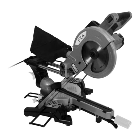
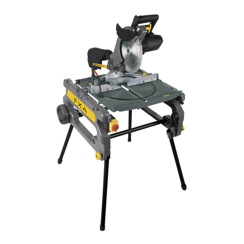
FXA FXAJ1G-ZP8-210C User manual

FXAJ1G-ZP8-210C
Instruction manual (Original instructions) GB pg 8-18
Käyttöohje (Alkuperäisten ohjeiden käännös) FI pg 19-28
Bruksanvisning (Översättning av originalinstruktionerna) SE pg 29-38
Bruksanvisning (Oversettelse av de opprinnelige instruksjonene) NO pg 39-48
Руководство пользователя (Перевод исходных инструкций) RU pg 49-59
Kasutusjuhend (Tõlgitud originaal juhendist) EE pg 60-69
Instrukcijas (Tulkojums no oriģinālvalodas) LV pg 70-79
Instaliavimo instrukcijos (Vertimas originali instrukcija) LT pg 80-89

2
(1) 2
13
5
1
12
8
16
1
17
4
6
9
10
19
14
11
18
3
7
15

3
(1A)
26
22
23
25
28
20
27
21
29
24

4
(2) (3)
(4) (5)
(6) (7)
(9)(8)

5
(10) (11)
(12) (13)
(14) (15)
(17)(16)

6
(18) (19)
(20) (21)
(22) (23)
(24) (25)

7
(26) (27)
(28)

8
IMPORTANT! Read all safety warnings, instructions, illustrations and specifications provided with this
power tool.
TÄRKEÄÄ! Lue tarkkaavaisesti kaikki tämän työkalun kanssa toimitetut varoitukset, ohjeet ja
spesifikaatiot, ja katso lisäksi kuvat.
VIKTIGT! Läs uppmärksamt alla varningar, instruktioner och specifikationer som bifogas med
detta verktyg och studera bilderna.
VIKTIG! Les nøye gjennom alle advarslene, instruksene og spesifikasjonene som følger med
verktøyet, og se på tegningene.
ВАЖНО! Пpoчтитe вce yкaзaния, инcтpyкции, иллюcтpaции и cпeцификaции, поставляемые
c электроинструментом.
TÄHTIS! Lugege läbi kõik elektrilise tööriista kohta esitatud ohuhoiatused ning tutvuge
tööriista jooniste ja tehniliste andmetega.
SVARĪGI! Izlasiet visus drošības brīdinājumus, instrukcijas, specifikācijas un apskatiet attēlus šī
elektroinstrumenta dokumentācijā.
SVARBU! Perskaitykite visus saugos įspėjimus, visas instrukcijas, paveikslėlius ir techninius
reikalavimus, pateikiamus su šiuo elektriniu įrankiu.

9
INTRODUCTION
Thankyou for purchasing this product which has
passed through our extensive quality assurance
process. Every care has been taken to ensure that it
reaches you in perfect condition.
SAFETY FIRST
Before attempting to operate this power tool the
following basic safety precautions should always be
taken to reduce the risk of fire, electric shock and
personal injury. It is important to read the instruction
manual to understand the application, limitations and
potential hazards associated with this tool.
CERTIFICATE OF GUARANTEE
This product is guaranteed for a period of 2 Years,
with effect from the date of purchase and applies only
to the original purchaser. This guarantee only applies
to defects arising from, defective materials and or
faulty workmanship that become evident during the
guarantee period only and does not include
consumable items. The manufacturer will repair or
replace the product at their discretion subject to the
following. That the product has been used in
accordance with the guide lines as detailed in the
product manual and that it has not been
subjected to misuse, abuse or used for a purpose for
which it was not intended. That it has not been taken
apart or tampered with in any way whatsoever or has
been serviced by unauthorised persons or has been
used for hire purposes. Transit damage is excluded
from this guarantee, for such damage the transport
company is responsible. Claims made under this
guarantee must be made in the first instance, directly
to the retailer within the guarantee period. Only under
exceptional circumstances should the product be
returned to the manufacturer. In these case it shall be
the consumer’s responsibility to return the product at
their cost ensuring that the product is adequately
packed to prevent transit damage and must be
accompanied with a brief description of the fault and
a copy of the receipt or other proof of purchase. The
manufacturer shall not be liable for any special,
exemplary, direct, indirect, incidental, or consequential
loss or damage under this guarantee. This guarantee
is in addition to and does not affect any rights, which
the consumer may have by virtue of the Sale of Goods
Act 1973 as amended 1975 and 1999.
STATUTORY RIGHTS
This guarantee is in addition to and in no way affects
your statutory rights.
PRODUCT DISPOSAL
When this product reaches the end of it’s life or is
disposed of for any other reason, it must not be
disposed of in household waste. In order to preserve
natural resources, and to minimise adverse
environmental impact, please recycle or dispose of
this product in an environmentally friendly way. It
should be taken to your local waste recycling centre
or other authorised collection and disposal facility.
If in doubt consult your local waste authority for
information regarding available recycling and / or
disposal options.
SPECIFIC SAFETY INSTRUCTIONS
Read all these instructions before attempting to
operate this product and save these instructions.
BLADE SAFETY
WARNING: Rotating Saw Blades are extremely
dangerous and can cause serious injury and
amputation. Always keep fingers and hands at least
150mm (6”) away from the blade at all times. Never
attempt to retrieve sawn material until the cutting
head is in the raised position, the guard is fully closed
and the saw blade has stopped rotating. Only use saw
blades that are recommended by the manufacturer
and that comply with the requirements of EN 847-1
Do Not use saw blades that are damaged or
deformed as they could shatter and cause serious
injury to the operator or bystanders.
Do Not use saw blades that are manufactured from
high speed steel (HSS).
Do not stop the blade by forcing the machine or by
using sideways pressure.
Do not use blades that are deformed or have missing
teeth. This is highly dangerous and could result in a
serious accident to the operator and bystanders as
well as damaging the machine.
Do not use blades that are larger than specified, only
use blades that are rated for the machine. The
rotational speed (min-1) shown on the blade should
always be HIGHER than the rotational speed (min-1)of
the machine.
Ensure that the directional arrow marked on the blade
corresponds with the rotational direction of the motor.
The teeth of the blade should always point downward
as viewed from the front of the saw.
If the table insert becomes damaged or worn it must
be replaced with an identical one available from the
manufacturer as detailed in this manual.
PERSONAL PROTECTIVE EQUIPMENT (PPE)
Hearing protection should be worn in order to reduce
the risk of induced hearing loss.
Eye protection should be worn in order to prevent the
possibility of the loss of sight from ejected chippings.
Respiratory protection is also advised as some wood
and wood type products especially MDF (Medium
Density Fibreboard) can produce dust that can be
hazardous to your health. We recommend the use of
an approved face mask with replaceable filters when
using this machine in addition to using the dust
extraction facility.
Gloves should be worn when handling blades or
rough material. It is recommended that saw blades
should be carried in a holder wherever practical.

10
It is not advisable to wear gloves when operating the
mitre saw.
SAFE OPERATION
Always ensure that you have selected the correct saw
blade for the material being cut. Do not use this mitre
saw to cut materials other than those specified below:
Wood
Wood derived products (MDF, Chipboard, Plywood,
Blockboard, Hardboard etc)
Aluminium
Mild Steel (6mm / 1/4” Thickness)
When transporting a mitre saw ensure that the cutting
head is locked in the 90° down position (if a sliding
mitre saw ensure that the slide bars are locked). Lift
the machine by gripping the outer edges of the base
with both hands (if a sliding mitre saw, transport using
the handles provided).
Under no circumstances shall the machine be lifted or
transported using the retractable guard or any part of
its operating mechanism.
Keep Guards in place and in good working order. With
the machine disconnected from the mains supply
check the operation of the guard to ensure that it
operates correctly.
Lower the saw head so that the blade is in its lowest
position, carefully rotate the blade by hand to ensure
that it is free from obstruction.
Repeat this procedure at all maximum mitre and bevel
positions before commencing operation of the Mitre
Saw.
Keep the work bench and floor area clear of all debris
including sawdust, chips and off-cuts.
Always keep the blade securing arbor and collars
clean.
Where it is necessary to use spacer or reducing rings
these must be suitable for the intended purpose and
only as recommended by the manufacturer.
If the mitre saw is fitted with a laser it shall not be
replaced with a different type. If the laser fails to
operate it shall be repaired or replaced by an
authorised service agent.
Whenever replacing blades ensure that the recessed
surface of the blade collar fits snugly against the
surface of the blade.
Ensure that the blade securing bolt is securely
tightened using the wrenches provided. Do not over
tighten.
Never attempt to retrieve off-cuts or any other part of
the work piece until the cutting head is in the raised
position, the guard is fully closed and the saw blade
has stopped rotating.
Wherever practicable always secure the work piece to
the saw table using the work clamp provided.
Always ensure that before each cut the mitre saw is
mounted in a stable position.
When cutting long work pieces use saw horses or
work benches to support the work piece, ensure that
all securing clamps are tight and check for excessive
play.
WARNING: the operation of any mitre saw can result
in foreign objects being thrown towards your eyes,
which could result in severe eye damage. Before
beginning power tool operation, always wear safety
goggles or safety glasses with side shield or a full face
shield when needed.
WARNING: If any parts are missing, do not operate
your mitre saw until the missing parts are replaced.
Failure to follow this rule could result in serious
personal injury.
ADDITIONAL SAFETY INSTRUCTIONS
Some wood and wood type products, especially MDF,
(Medium Density Fibreboard) can produce dust that
can be hazardous to your health. We recommend the
use of an approved face mask with replaceable filters
when using this machine in addition to using the dust
extraction facility. Ensure that power tools are
disconnected from the mains supply when not in use,
before servicing, lubricating or making adjustments
and when changing accessories such as blades.
Before commencing any cut allow the blade to reach
its full speed, let it run for a few seconds. If any
unusual noise or vibration is heard STOP the machine
immediately, and investigate the cause.
Never try to cut free hand. Always ensure that the
work piece is securely pressed against the back fence
and table support surface.
Ensure that the work piece that is being cut off has
sufficient room to move sideways. Failure to do so
may result in the off cut binding against the blade.
If the work piece cannot be held securely by hand
then use the jig or clamp to hold it in place whilst it is
being cut.
Ensure that irregular or round pieces are held securely
so that they are unable to move or twist and pinch the
blade.
Never cut more than one piece at a time.
Never cut pieces that are too small to be held
securely against the back fence with the thumb and
index finger.
Use only blades that are recommended by the
manufacturer.
Do not start the machine with the blade in contact
with the work piece.

11
Check the work piece for any protruding nails, screw
heads or anything that could damage the blade.
Do not attempt to modify the machine or its
accessories in any way.
Do not use excessive force when feeding the work
piece to the blade.
Feeding the work piece gradually will reduce wear on
the machine and blade increasing its efficiency and
operating life.
Do not use the saw without guards in position.
Replace table insert when worn.
Do not use the saw to cut material other than
aluminum, wood or similar materials.
Connect mitre saws to a dust collecting device when
sawing.
Select saw blades in relation to the material to be cut.
Take care when slotting.
WARNING! DO NOT ATTEMPT TO CUT MATERIAL
LARGER THAN THE MAXIMUM CUTTING CAPACITY.
ADDITIONAL SAFETY ADVICE CARRYING YOUR
MITRE SAW
Although compact, this Mitre Saw is heavy. To reduce
the risk of back injury, get competent help whenever
you have to lift the saw.
To reduce the risk of back injury, hold the tool close
to your body when lifting. Bending your knees so you
can lift with your legs, not your back. Lift by using the
handheld areas at each side of the machines base.
Never carry the Mitre Saw by the power cord.
Carrying the Mitre Saw by the power cord could
cause damage to the insulation or the wire
connections resulting in electric shock or fire.
Before moving the Mitre Saw tighten the mitre and
bevel locking screws and the sliding carriage locking
screw to guard against sudden unexpected
movement.
Lock the Cutting Head in its lowest position. Ensure
that the Cutting Head Locking Pin is completely
engaged in its socket.
WARNING: Do not use the blade guard as a ‘lifting
point’. The power cord must be removed from the
power supply before attempting to move the machine.
SAFETY RULES FOR LASER LIGHTS
The laser light/laser radiation used is Class 2 with
maximum 1mW power and 650nm wavelength.
These lasers do not normally present an optical
hazard, although staring at the beam may cause flash
blindness.
WARNING. Do not stare directly at the laser beam. A
hazard may exist if you deliberately stare into the
beam, please observe all safety rules as follows:
The laser shall be used and maintained in accordance
with the manufacturer’s instructions.
Never aim the beam at any person or an object other
than the workpiece.
The laser beam shall not be deliberately aimed at
personnel and shall be prevented from being directed
towards the eye of a person for longer than 0.25s.
Always ensure the laser beam is aimed at a sturdy
workpiece without reflective surfaces.l.e. wood or
rough coated surfaces are acceptable.
Bright shiny reflective sheet steel or the like is not
suitable for laser use as the reflective surface could
direct the beam back at the operator.
Do not change the laser light assembly with a different
type. Repairs must be carried out by the laser
manufacturer or an authorised agent.
GENERAL SAFETY RULES
WARNING! Read all instructions Failure to follow all
instructions listed below may result in electric shock,
fire and/or serious injury. The term "power tool" in all
of the warnings listed below refers to your mains
operated (corded) power tool or battery operated
(cordless) power tool.
SAVE THESE INSTRUCTIONS
1) WORK AREA
a) Keep work area clean and well lit. Cluttered and
dark areas invite accidents.
b) Do not operate power tools in explosive
atmospheres, such as in the presence of
flammable liquids, gases or dust. Power tools
create sparks which may ignite the dust or fumes.
c) Keep children and bystanders away while
operating a power tool. Distractions can cause you
to lose control.
2) ELECTRICAL SAFETY
a) Power tool plugs must match the outlet. Never
modify the plug in any way. Do not use any
adapter plugs with earthed (grounded) power
tools. Unmodified plugs and matching outlets will
reduce risk of electric shock.
b) Avoid body contact with earthed or grounded
surfaces such as pipes, radiators, ranges and
refrigerators. There is an increased risk of electric
shock if your body is earthed or grounded.
c) Do not expose power tools to rain or wet
conditions. Water entering a power tool will
increase the risk of electric shock.

12
d) Do not abuse the cord. Never use the cord for
carrying, pulling or unplugging the power tool.
Keep cord away from heat, oil, sharp edges or
moving parts. Damaged or entangled cords
increase the risk of electric shock.
e) When operating a power tool outdoors, use an
extension cord suitable for outdoor use. Use of a
cord suitable for outdoor use reduces the risk of
electric shock.
3) PERSONAL SAFETY
a) Stay alert, watch what you are doing and use
common sense when operating a power tool. Do
not use a power tool while you are tired or under
the influence of drugs, alcohol or medication.
A moment of inattention while operating power
tools may result in serious personal injury.
b) Use safety equipment. Always wear eye
protection. Safety equipment such as dust mask,
non-skid safety shoes, hard hat, or hearing
protection used for appropriate conditions will
reduce personal injuries.
c) Avoid accidental starting. Ensure the switch is in
the off position before plugging in. Carrying power
tools with your finger on the switch or plugging in
power tools that have the switch on invites
accidents.
d) Remove any adjusting key or wrench before
turning the power tool on.
A wrench or a key left attached to a rotating part
of the power tool may result in personal injury.
e) Do not overreach. Keep proper footing and
balance at all times. This enables better control of
the power tool in unexpected situations.
f) Dress properly. Do not wear loose clothing or
jewellery. Keep your hair, clothing and gloves
away from moving parts. Loose clothes, jewellery
or long hair can be caught in moving parts.
g) If devices are provided for the connection of dust
extraction and collection facilities, ensure these
are connected and properly used. Use of these
devices can reduce dust related hazards.
4) POWER TOOL USE AND CARE
a) Do not force the power tool. Use the correct
power tool for your application. The correct power
tool will do the job better and safer at the rate for
which it was designed.
b) Do not use the power tool if the switch does not
turn it on and off. Any power tool that cannot be
controlled with the switch is dangerous and must
be repaired.
c) Disconnect the plug from the power source before
making any adjustments, changing accessories, or
storing power tools. Such preventive safety
measures reduce the risk of starting the power
tool accidentally.
d) Store idle power tools out of the reach of children
and do not allow persons unfamiliar with the
power tool or these instructions to operate the
power tool. Power tools are dangerous in the
hands of untrained users.
e) Maintain power tools. Check for misalignment or
binding of moving parts, breakage of parts and
any other condition that may affect the power
tools operation. If damaged, have the power tool
repaired before use. Many accidents are caused
by poorly maintained power tools.
f) Keep cutting tools sharp and clean. Properly
maintained cutting tools with sharp cutting edges
are less likely to bind and are easier to control.
g) Use the power tool, accessories and tool bits etc.,
in accordance with these instructions and in the
manner intended for the particular type of power
tool, taking into account the working conditions
and the work to be performed. Use of the power
tool for operations different from intended could
result in a hazardous situation.
5) SERVICE
a) Have your power tool serviced by a qualified repair
person using only identical replacement parts. This
will ensure that the safety of the power tool is
maintained.

13
COMPONENTS & CONTROLS (FIG 1 & 1A)
UNPACKING
Caution! This packaging contains sharp objects. Take
care when unpacking. Remove the machine, together
with the accessories supplied, from the packaging.
Check carefully to ensure that the machine is in good
condition and account for all the accessories listed in
this manual. Also make sure that all the accessories
are complete. If any parts are found to be missing, the
machine and its accessories should be returned
together in their original packaging to the retailer.
Do not throw the packaging away, keep it safe
throughout the guarantee period, then recycle if
possible, otherwise dispose of it by the proper means.
Do not let children play with empty plastic bags due
to the risk of suffocation.
ACCESSORIES
Only fit genuine replacement parts which comply with
the speed and fit of the power tool.
The FXAJ1G-ZP8-210C comes with the following
accessories:
• 48 Teeth blade (fitted)
•Dustbag
• Work clamp
• Side extension arms (x 2)
• 6mm saw blade allen key
ASSEMBLY
Note: Before carrying out any assembly or
disassembly of the unit please ensure that the unit is
not connected to the electrical supply.
TRANSPORTATION (FIG.2)
Lift the mitre saw only when the saw arm is locked in
the down position, the saw is switched off and the
plug is removed from the power socket. You must
only lift the saw by the castings. Do not lift the saw
using the guards.
BENCH MOUNTING (FIG.3)
The saw base has 4 mounting holes to facilitate bench
mounting. Attach the saw to a level, horizontal bench
or work table using bolts (not supplied) though the
fixing holes in the saw base.
NOTE. If desired, you can mount the saw to a piece of
8 mm or thicker plywood which can then be clamped
to your work support or moved to other job sites and
reclamped.
CAUTION. Make sure that the mounting surface is not
warped as an uneven surface can cause binding and
inaccurate sawing.
SIDE EXTENSION ARMS (FIG.4)
Slide the supports into the holes in the side of base
casting. Tighten the side support bar locking screw to
secure the side extension arms in place, (Fig.4).
NOTE: The side support bar locking screw must be
securely tightened before placing the workpiece on
the saw.
DUST BAG (FIG.5)
The dust bag fits onto the dust extractor port.
Squeeze the two metal tabs on the end of the dust
extraction bag to allow it to slide over the dust
extractor port.
For efficient operation, empty the dust bag when it is
no more than half full.
This allows better airflow through the bag. A dust
extraction system may also be connected to the dust
extraction port for a cleaner and safer work area.
1. Dust bag
2. Dust extraction port
3. Upper fixed blade guard
4. Release latch
5. Operating handle
6. Rotating blade guard
7. Side support bar location holes (2 sets)
8. Table insert (kerf plate)
9. Mitre lock handle
10. Mitre lock release latch
11. 6mm Allen key
12. Side extension arm (left)
13. Side extension arm (right)
14. Clamp assembly
15. Side support bar locking screw
16. Table fence
17. Slide bars
18. Mitre table
19. Mitre scale
20. On/off trigger switch
21. Trenching depth adjustment screw
22. Slide lock knob
23. Bevel lock
24. 0° Bevel adjustment screw
25. Clamp assembly lock screw (x 2)
26. Release knob
27. Trenching depth lock nut
28. Bevel scale
29. Spindle lock button

14
FITTING THE CLAMP ASSEMBLY (FIG.6)
Two sockets (one either side) are incorporated into the
rear of the machines fence. These sockets are for
positioning the Clamp Assembly.
Fit the clamp to the retaining socket that best suits
the cutting application, ensuring that it is fully pushed
down.
Using a screwdriver, tighten the clamp assembly lock
screw to lock the pillar of the clamp into the fence
socket, Fig.6.
Place the workpiece to be cut onto the saw table,
against the fence and in the desired position.
Adjust the clamp using the thumbscrews and hand-
wheel so that it securely holds the workpiece to the
saw table.
Conduct a ‘dry run’ with the power disconnected.
Ensure that the Clamp does not interfere with the path
of the blade, or with the path of any other part of the
cutting head as it is lowered.
SETTING THE TABLE SQUARE WITH THE BLADE
Make sure that the electrical plug is removed from the
power point.
Push the saw arm down to its lowest position by
pressing the release latch, Fig.7, and engage the
release knob to hold the saw arm in the transport
position, Fig.8.
Fit the mitre lock handle (Fig.9).
Rotate the table until the pointer is positioned at 0º.
Tighten the mitre lock handle. (Fig.10)
Loosen the bevel lock and set the saw arm at 0º bevel
(the blade at 90º to the mitre table). (Fig.11)
Tighten the bevel lock, Fig.12.
Place a set square against the table and the flat part
of the blade (Fig.13).
NOTE. Make sure that the square contacts the flat
part of the saw blade, not the teeth. Rotate the blade
by hand and check the blade-to-table alignment at
several points. The edge of the set square and the
saw blade should be parallel.
If the saw blade angles away from the set square,
adjust as follows:
Loosen the bevel lock. (Fig.15)
Use 10mm spanner or adjustable spanner to adjust
the lock nut (Fig, 16), make sure the edge of set
square and saw blade should be parallel.
Tighten the bevel lock.
Loosen the screw holding the pointer of the bevel
scale and adjust the position of the pointer so that it
accurately indicates zero on the scale. Retighten the
screw, Fig.17.
Retighten the bevel lock and the lock nut securing the
0° bevel adjustment screw.
NOTE. The above procedure can also be used to
check the angle of the saw blade to the table at 45º
bevel angle. The 45° bevel adjustment screw is on the
opposite side of the saw arm.
TRENCH DEPTH ADJUSTMENT
In its normal position, the trenching stop permits the
saw blade to cut right through a workpiece.
To adjust the trench stop pull out the release knob out
and fully raise the saw arm (Fig.18)
When the saw arm is lifted, the trenching stop can be
adjusted so that the trenching depth adjustment
screw contacts the stop as the saw arm is lowered.
Deploy the stop by moving it outwards, Fig.19. If the
trenching stop wont move, slightly loosen the screw
using a crosshead screwdriver.
This restricts the cut to a “trench” in the workpiece.
The depth of the trench can be adjusted with the
trenching depth adjustment screw and locked in
position with the trenching depth lock nut (Fig.20).
OPERATION
Hold the operating handle firmly and squeeze the
switch trigger, (Fig.21).
Press the release latch (Fig.22).
When the blade is at its maximum speed
(approximately 2 seconds), lower the blade through
the workpiece (Fig.23). After completing the cut,
release the switch trigger and allow the saw blade to
stop rotating before raising the blade out of the
workpiece. Wait until the blade stops before removing
the workpiece.
CROSS-CUTTING (WITHOUT SLIDING FUNCTION)
To saw narrow pieces of wood, the slide function is
not necessary. In these cases, ensure that the slide
lock is screwed down to prevent the saw arm from
sliding, Fig.24.
A crosscut is made by cutting across the grain of the
workpiece. A 90º crosscut is made with the mitre
table set at 0º. Mitre crosscuts are made with the
table set at some angle other than zero.
Pull on the release knob and lift the saw arm to its full
height.
Loosen the mitre lock. Rotate the mitre table until the
pointer aligns with the desired angle. Retighten the
mitre lock.
WARNING. Be sure to tighten the mitre lock before
making a cut. Failure to do so could result in the table
moving during the cut and cause serious personal
injury.

15
Place the workpiece flat on the table with one edge
securely against the fence. If the board is warped,
place the convex side against the fence. If the
concave side is placed against the fence, the board
could break and jam the blade.
When cutting long pieces of timber, support the
overhanging ends of the timber with the side
extension arms, a roller stand or a work surface that is
level with the saw table.
Use the clamp assembly to secure the workpiece
wherever possible.
It is possible to remove the clamp assembly by
loosening the clamp assembly lock and moving it to
the other side of the table. Make sure the clamp
assembly lock is tight before using the clamp.Before
turning on the saw, perform a dry run of the cutting
operation to check that there are no problems.
Hold the operating handle firmly and squeeze the
switch trigger. Allow the blade to reach maximum
speed.
Press the release latch and slowly lower the blade into
and through the workpiece.
Release the switch trigger and allow the saw blade to
stop rotating before raising the blade out of the
workpiece. Wait until the blade stops before removing
the workpiece.
CROSS-CUTTING (WITH SLIDE ACTION)
When cutting wide workpieces, first unscrew the slide
lock, Fig.24.
Pull on the release knob, raise the saw arm to its
highest position and slide it towards you.
Hold the handle firmly and squeeze the switch trigger.
Allow the blade to reach maximum speed. Press the
release latch and slowly lower the blade into the
workpiece and slide it away from you at the same
time until the workpiece is cut.
Release the switch trigger and allow the saw blade to
stop rotating before raising the blade out of the
workpiece.
Wait until the blade stops before removing the
workpiece.
BEVEL CUT
A bevel cut is made by cutting across the grain of the
workpiece with the blade angled to the fence and
mitre table. The mitre table is set at the zero degree
position and the blade set at an angle between 0º and
45º to the left, Fig.25.
Repeat the steps for cross-cutting (with or without
slide function).
Loosen the bevel lock and move the saw arm to the
left to the desired bevel angle (between 0º and 45º).
Tighten the bevel lock.
WARNING: Always ensure that the bevel lock is fully
tightened before making a cut.
COMPOUND MITRE CUT
A compound mitre cut involves using a mitre angle
and a bevel angle at the same time.
It is used in making picture frames, to cut mouldings,
making boxes with sloping sides and for roof framing.
Always make a test cut on a piece of scrap wood
before cutting into the good material.
Use the slide action when cutting wide workpieces.
MAINTENANCE & CARE
CHANGING A BLADE
DANGER: The blade is extremely sharp and care must
be observed when handling. Never try to use a blade
larger than the stated capacity of the saw. It might
come into contact with the blade guards. Never use a
blade that is too thick to allow the outer blade washer
to engage with the flats on the spindle.
It will prevent the blade bolt from properly securing
the blade on the spindle.
Do not use the saw to cut metal or masonry.
Ensure that any spacers and spindle rings that may be
required suit the spindle and the blade fitted.
Make sure that the electrical plug is removed from the
power point.
Push down on the operating handle and pull the
release knob to disengage the saw arm.
The release knob can be turned so that it is held in the
retracted position.
Raise the saw arm to its highest position.
Rotate the lower blade guard (Fig.26) up and into the
upper blade guard and press the spindle lock button
(Fig.27). Rotate the blade until the spindle locks.
Use the 6mm Allen key wrench to remove the blade
bolt (Fig.28). (Loosen in a clockwise direction as the
blade screw has a left hand thread).
Remove the washer, outer blade flange and the blade.
Wipe a drop of oil onto the inner blade washer and
the outer blade washer where they contact the blade.
Fit the new blade onto the spindle taking care that the
inner blade washer sits behind the blade.
CAUTION. To ensure correct blade rotation, always
install the blade with the blade teeth and the arrow
printed on the side of the blade pointing down
(Fig.28).
The direction of blade rotation is also stamped with an
arrow on the upper blade guard.
Replace the outer blade washer.

16
Depress the spindle lock button and replace the blade
bolt.
Use the 6mm Allen key wrench to tighten the blade
screw securely (anti-clockwise).
Check that the blade guard operates correctly and
covers the blade as the saw arm is lowered.
Connect the saw to the power supply and run the saw
to make certain that it is operating correctly.
Note: Check the tightness of the blade securing bolt
before, during and after each use.
MAINTENANCE
Keep the tool's air vents unclogged and clean at all
times.
Regularly check to see if any dust or foreign matter
has entered the grills near the motor and around the
trigger switch. Use a soft brush to remove any
accumulated dust. Wear safety glasses to protect
your eyes whilst cleaning.
Re-lubricate all moving parts at regular intervals.
If the body of the saw needs cleaning, wipe it with a
soft damp cloth. A mild detergent can be used but
nothing like alcohol, petrol or other cleaning agent.
Never use caustic agents to clean plastic parts.
CAUTION. Water must never come into contact with
the saw.
GENERAL INSPECTION
Check regularly that all fixation screws are sufficiently
tightened. Check especially the outer flange. If there is
vibration, screws can loosen with time.
Regularly check the device’s power cable and all
extension cables used for damage. If the supply cord
needs replacing, the task must be carried out by the
manufacturer, the manufacturer’s agent, or an
authorised service centre in order to avoid a safety
hazard. Replace damaged extension cables.
TECHNICAL SPECIFICATION
NOISE AND VIBRATION DATA
A weighted sound pressure: LpA 93.6dB(A)
A weighted sound power: LWA106.6 dB(A)
Uncertainty K K=3dB(A)
Voltage 230 V~ 50 Hz
Rated input 1500W
No load speed 4500 min-1
Saw Blade diameter Ø210mm
Teeth 48 HW
Saw Blade arbour Ø 30mm
Angle of mitre table -45°/0°/+45°
Bevel angles 45° to the left
Straight cut at 0° x 0° 305 x 70 mm
Mitre cut at 45° x 0° 215 x 70 mm
Bevel cut at 0° x 45° 305 x 35 mm
Combined Mitre cut at 215 x 35 mm
45° x 45°
Weight 11.0 kg

17
SYMBOLS
The rating plate on your tool may show symbols. These represent important information about the product or
instructions on its use.
Conforms to relevant safety
standards.
Read the instruction manual.
Product conforms to RoHs
requirements
Waste electrical products should
not be disposed of with
household waste. Please recycle
where facilities exist. Check with
your Local Authority or retailer for
recycling advice.
General warning
Double insulated for additional
protection.
Wear hearing protection.
Wear eye protection.
Wear respiratory protection.
Cutting danger.
Do NOT clean, lubricate or repair
while the machine is running
Danger! Splinter casing
Dangerous voltage.
Do NOT approach the machine
with loose clothing
Do NOT remove safety guards
and devices with the machine
operating
Protect the machine from foul
weather
Do NOT touch the moving blade

18
ENVIRONMENTAL PROTECTION
Information for (private householders) for the environmentally responsible disposal of Waste Electrical and
Electronic Equipment (WEEE)
This symbol on products and or accompanying documents indicates that used and end of life
electrical and electronic equipment should not be disposed of in household waste. For the
proper disposal, treatment, recovery and recycling, please take these products to designated
collection points, where they will be accepted on a free of charge basis. Alternatively, in some
countries you may be able to return your products to your retailer upon the purchase of an
equivalent new product. Disposing of this product correctly will help to save valuable resources
and prevent any potential adverse effects on human health and the environment which could
otherwise arise from inappropriate waste disposal and handling. Please contact your local
authority for further details of your nearest designated collection point. Penalties may be applicable for incorrect
disposal of this waste in accordance with national legislation.
FOR BUSINESS USERS IN THE EUROPEAN UNION.
If you wish to discard electrical and electronic equipment, please contact your dealer or supplier for further
information.
Information on Disposal in other Countries outside the European Union.
This Symbol is only valid in the European Union.
If you wish to dispose of this product, please contact your local authorities or dealer and ask for the correct
method of disposal.

19
ESITTELY
Kiitos, että ostit tämän tuotteen, joka on läpäissyt
kattavan laatutarkastusprosessimme. Kaikki on tehty
sen varmistamiseksi, että saat sen täydellisessä
toimintakunnossa.
TURVALLISUUS ENSIN
Seuraavat perusvarotoimet on tehtävä ennen
sähkötyökalun käyttämistä tulipalojen, sähköiskujen ja
henkilövahinkojen estämiseksi. On tärkeää lukea nämä
käyttöohjeet, jotta ymmärrät tämän työkalun käytön,
siihen liittyvät rajoitukset ja potentiaaliset vaarat.
TAKUUTODISTUS
Tällä tuotteella on 2 vuoden takuu, joka alkaa
ostopäivästä ja koskee vain ensimmäistä ostajaa.
Tämä takuu kattaa vain virheet, jotka aiheutuvat
raaka-aine- ja valmistusvioista, ja jotka tulevat esille
takuuaikana. Takuu ei korvaa kuluvia osia. Valmistaja
korjaa tai vaihtaa tuotteen harkintansa mukaan
edellyttäen seuraavassa mainittuja asioita. Tuotetta on
käytetty käsikirjan ohjeiden mukaisesti, ja sitä ei ole
käytetty väärin tai huolimattomasti tai tarkoitukseen,
johon sitä ei ole tarkoitettu käytettäväksi. Laitetta ei
ole purettu osiin tai peukaloitu millään tavalla, sitä ei
ole huollatettu valtuuttamattomilla henkilöillä tai
käytetty vuokrauksen kohteena. Kuljetusvauriot eivät
kuulu tämän takuun piiriin. Niistä on vastuussa
kuljetusliike. Takuuvaateet on esitettävä ensisijaisesti
suoraan jälleenmyyjälle takuukauden aikana. Tuote
tulee palauttaa valmistajalle vain poikkeuksellisissa
tapauksissa. Näissä tapauksissa ostajan vastuulla on
tuotteen palauttaminen omalla kustannuksellaan ja
varmistaen, että se on asianmukaisesti pakattu
kuljetusvaurioiden estämiseksi. Mukaan tulee liittää
lyhyt kuvaus viasta ja kopio kuitista tai muusta
ostotodistuksesta. Valmistaja ei ole vastuussa mistään
erityisistä, esimerkillisistä, suorista, välillisistä,
satunnaisista tai epäsuorista menetyksistä tai
vahingoista takuun aikana. Tämä takuu tulee lisänä,
eikä vaikuta oikeuksiin, joita kuluttajalla saattaa olla
vuoden 1973 Tavaranmyyntilain ja siihen vuonna 1975
ja 1999 tehtyjen muutosten mukaisesti.
LAKISÄÄTEISET OIKEUDET
Tämä takuu on lisänä, eikä vaikuta lakisääteisiin
oikeuksiisi.
TUOTTEEN HÄVITTÄMINEN
Kun tuotteen käyttöikä loppuu tai se hävitetään
jostakin muusta syystä, sitä ei saa hävittää
kotitalousjätteen mukana. Luonnonvarojen
säilyttämiseksi ja haitallisten ympäristövaikutusten
minimoimiseksi, kierrätä tuote tai hävitä muulla
ympäristöystävällisellä tavalla. Tuote tulee viedä
paikalliseen kierrätyskeskukseen tai muuhun
viralliseen keräily- ja hävityspisteeseen.
Jos olet epävarma, kysy kierrätys- ja/tai
hävittämisvaihtoehdoista paikalliselta jäteliikkeeltä.
ERITYISET TURVAOHJEET
Lue kaikki ohjeet ennen kuin yrität käyttää laitetta.
Säilytä nämä ohjeet.
TERÄN TURVALLISUUS
VAROITUS: Pyörivät sahanterät ovat erittäin vaarallisia
ja voivat aiheuttaa vakavia henkilövahinkoja ja raajojen
leikkautumisia. Pidä sormet ja kädet aina vähintään
150 mm:n etäisyydellä terästä. Älä yritä poistaa
sahattua materiaalia ennen kuin leikkuupää on
nostettu yläasentoon, suojus on täysin suljettu ja
sahanterä on lopettanut pyörimisen. Käytä vain
valmistajan suosittelemia ja standardin EN 847-1
mukaisia sahanteriä.
Älä käytä sahanteriä, jotka ovat vaurioituneita tai
vääntyneitä, koska ne voivat haljeta ja aiheuttaa
vakavan henkilövahingon käyttäjälle tai sivullisille.
Älä käytä pikateräksestä (HSS) valmistettuja
sahanteriä.
Älä pysäytä terää pakottamalla tai käyttäen sivuttaista
painamista.
Älä käytä vääntyneitä teriä tai teriä, joista puuttuu
hampaita. Tämä on erittäin vaarallista ja saattaa
aiheuttaa vakavan vahingon käyttäjälle ja vieressä
oleville sekä vaurioittaa konetta.
Älä käytä teriä, jotka ovat määriteltyä isompia. Käytä
vain koneelle mitoitettuja teriä. Terässä näkyvän
pyörimisnopeuden (min-1) tulee aina olla SUUREMPI
kuin koneen pyörimisnopeus (min-1).
Varmista, että terään merkitty suuntanuoli vastaa
moottorin pyörimissuuntaa. Terän hampaiden tulee
aina osoittaa alaspäin sahan edestä katsottuna.
Jos pöydän kitakappale vaurioituu tai kuluu, se täytyy
vaihtaa samanlaiseen. Niitä saa valmistajalta tämän
käyttöoppaan ohjeiden mukaisesti.
HENKILÖNSUOJAIMET (PPE)
Käytä kuulosuojaimia kuulovaurioriskin
pienentämiseksi.
Suojalaseja tulee käyttää, jotta estetään sinkoutuvien
lastujen aiheuttama mahdollinen näkökyvyn menetys.
SÄHKÖISET TIEDOT
TÄRKEÄÄ
Tämä tuote on varustettu sinetöidyllä sähköpistokkeella, joka sopii työkalulle ja käyttömaassa käytetylle virralle ja
vastaa kansainvälisiä standardeja.
Laite tulee kytkeä arvokilvessä ilmoitettuun jännitteeseen. Jos pistoke tai sähköjohto on vaurioitunut, ne tulee
vaihtaa täysin samanlaiseen sarjaan.
Noudata aina käyttömaassa voimassa olevia sähköverkkoon kytkemistä koskevia lakeja.
Ota tarvittaessa aina yhteys ammattitaitoiseen sähköasentajaan.

20
Hengityssuojain on myös suositeltava. Jotkin puut tai
puuntyyppiset tuotteet, etenkin MDF (puolikova
kuitulevy), voivat tuottaa pölyä, joka saattaa olla
vaarallista terveydellesi. Laitetta käytettäessä
suosittelemme käyttämään pölynpoistolaitteen lisäksi
hyväksyttyä kasvonaamiota, jossa on vaihdettavat
suodattimet.
Käytä käsineitä teriä tai karkeita materiaaleja
käsitellessäsi. Suosittelemme kuljettamaan sahanterät
kotelossa aina, kun mahdollista.
Emme suosittele käsineiden käyttöä, kun käytät
jiirisahaa.
TURVALLINEN KÄYTTÖ
Varmista, että olet valinnut oikean sahanterän
sahattavalle materiaalille. Älä käytä tätä jiirisahaa
muiden materiaalien kuin alla mainittujen
sahaamiseen:
Puu
Puuperäiset tuotteet (MDF, lastulevy, vaneri,
kimpilevy, kovalevy jne.)
Alumiini
Niukkahiilinen teräs (max paksuus 6 mm/1/4”)
Kun kuljetat jiirisahaa, varmista, että sahanpää on
lukittu alas 90 asteen asentoon (jos liukuva jiirisaha,
varmista, että liukupalkit on lukittu). Nosta konetta
tarttumalla molemmilla käsillä sen pohjan
ulkoreunoista (jos liukuva jiirisaha, nosta siinä olevista
kahvoista).
Missään tapauksessa konetta ei saa nostaa tai
kuljettaa vetämällä suojuksesta tai mistään
käyttömekanismin osasta.
Pidä suojukset paikoillaan ja hyvässä
toimintakunnossa. Tarkista suojusten moitteeton
toiminta, kun kone on irrotettuna verkkovirrasta.
Paina sahanpää alas niin, että terä on alimmassa
asennossaan, pyöritä terää varovasti kädellä
varmistaaksesi, että se pyörii esteettömästi.
Toista tämä toimenpide kaikissa maksimi viiste- ja
vinosahausasennoissa ennen kuin aloitat jiirisahan
käytön.
Pidä työpenkki ja lattia-alue puhtaana
irtomateriaalista, kuten lastuista ja sahatuista
kappaleista.
Pidä aina sahanterä ja sahanterän laippa puhtaina.
Jos aluslevyjen tai supistusrenkaiden käyttö on
välttämätöntä, niiden täytyy olla tarkoitukseen sopivia
ja valmistajan suosittelemia.
Jos jiirisaha on varustettu laserilla, älä vaihda laseria
toisen tyyppiseen. Jos laser ei toimi, se täytyy korjata
tai vaihtaa valtuutetussa huoltoliikkeessä.
Aina kun vaihdat teriä varmista, että sahanterän
kauluksen uritettu pinta on terän pintaa vasten.
Varmista, että terän kiinnityspultti on kunnolla kiristetty
käyttäen mukana tullutta avainta. Älä kiristä liikaa.
Älä yritä poistaa sahattua materiaalia tai muita
työkappaleen osia ennen kuin leikkuupää on nostettu
yläasentoon, suojus on täysin suljettu ja sahanterä on
lopettanut pyörimisen.
Kiinnitä työkappale sahauspöytään puristinkiinnikkeillä
aina, kun se on mahdollista.
Varmista aina ennen jokaista sahausta, että jiirisaha on
asennettu vakaaseen asentoon.
Pitkiä kappaleita sahattaessa käytä sahapukkeja tai
työpenkkejä työkappaleen tukemiseen ja varmista,
että kaikki kiinnittimet on kiristetty ja tarkista liika
välys.
VAROITUS: minkä tahansa jiirisahan käyttö voi
aiheuttaa vieraiden esineiden sinkoutumisen kohti
silmiä ja aiheuttaa vakavan silmävaurion. Käytä aina
suojalaseja tai sivusuojilla varustettuja suojalaseja tai
kokonaamaria, kun käytät sähkötyökalua.
VAROITUS: Jos jiirisahasta puuttuu osia, älä käytä sitä
ennen kuin osat on korvattu uusilla. Tämän säännön
noudattamatta jättäminen voi johtaa vakavaan
henkilövahinkoon.
LISÄTURVAOHJEET
Jotkin puut tai puuntyyppiset tuotteet, etenkin MDF
(puolikova kuitulevy), voivat tuottaa pölyä, joka saattaa
olla vaarallista terveydellesi. Laitetta käytettäessä
suosittelemme käyttämään pölynpoistolaitteen lisäksi
hyväksyttyä kasvonaamiota, jossa on vaihdettavat
suodattimet. Varmista, että sähkötyökalut on irrotettu
verkkovirrasta, kun niitä ei käytetä sekä ennen
huoltoa, voitelemista tai säätöjen tekemistä sekä
varusteiden, kuten terien, vaihdon aikana.
Anna sahanterän saavuttaa täysi nopeus ja käydä
tyhjäkäynnillä muutama sekunti ennen sahauksen
aloittamista. Mikäli havaitset epätavallista ääntä tai
tärinää, PYSÄYTÄ laite välittömästi ja tarkista
ongelman aiheuttaja.
Älä koskaan sahaa vapaalla kädellä. Varmista aina,
että työkappale on tiukasti painettu takavastetta ja
pöydän tukipintaa vasten.
Varmista, että irti sahattavalla työkappaleella on
riittävä tila liikkua sivusuunnassa. Tämän
noudattamatta jättäminen saattaa johtaa irti
sahattavan osan jumittumiseen terää vasten.
Mikäli työstettävää kappaletta ei voida pitää kunnolla
kiinni käsin, käytä kiinnitintä tai puristinta pitämään
sitä paikallaan.
Varmista, että epäsäännölliset tai pyöreät kappaleet
on kiinnitetty kunnollisesti, jotta ne eivät pääse
liikkumaan tai kääntymään ja jumittamaan terää.
Älä koskaan sahaa enempää kuin yhden kappaleen
kerrallaan.
Table of contents
Languages:
Other FXA Saw manuals

FXA
FXA FXA502024131 User manual

FXA
FXA FXAM1H-ZP5-250-1 User manual

FXA
FXA 501739306 User manual

FXA
FXA FXAM1H-ZP2-1-250F User manual

FXA
FXA FXAJD5385 User manual

FXA
FXA FXAJF92109P User manual

FXA
FXA FXA92502 User manual

FXA
FXA FXAM1H-ZP5-250-1 User manual

FXA
FXA FXAJ0G-ZP-185Li-JD User manual

FXA
FXA JD5385 User manual