Gacell CT-15000 User manual

Battery Charger User Guide
MODEL: CT-15000
AC Input:220-240VAC, 50-60Hz, 2.5A
DC Output: 12VDC, 15A;
24VDC, 7.5A;
12VDC, 20A (5 minutes)
Temperature Controlled
Please read and understand all important safety and operating
instructions before using this charger. In addition, please read and follow
all battery and vehicle manufacturer’s instructions and cautionary
markings.

1
IMPORTANT SAFETY INSTRUCTIONS
SAFETY PRECAUTIONS FOR WORKING IN THE VICINITY OF A BATTERY
1) Batteries generate explosive gases during normal operation. Use in
well-ventilated area.
2) Consider having someone close enough or within the range of your
voice to come to your aid when you work near a battery.
3) Do NOT smoke, strike a match, or cause a spark in vicinity of battery
or engine. Avoid explosive gas, flames and sparks.
4) Remove all personal jewelry, such as rings, bracelets, necklaces, and
watches while working with a vehicle battery. These items may produce
a short-circuit that could cause severe burns.
5) Be extra cautious to reduce risk of dropping a metal tool onto the
battery. It might spark or short-circuit a battery or other electrical
hardware which may cause an explosion or fire.
6) Wear complete eye protection, hand and clothing protection. Avoid
touching eyes while working near a battery.
7) Study all battery manufacturer’s specific precautions such as
removing or not removing cell caps while charging and recommended
rates of charge.
8) Clean battery terminals before connected with the charger. Be careful
to keep corrosion from coming in contact with eyes.
9) When it is necessary to remove a battery from vehicle to charge,
always remove grounded terminal from battery first. Make sure all
accessories in the vehicle are off in order to prevent an arc.
10) It is NOT intended to supply power to an extra-low-voltage electrical
system or to charge dry-cell batteries. Charging dry-cell batteries may
burst and cause injury to persons and property.
11) NEVER charge a frozen, damaged, leaking or non-rechargeable
battery.
12) If battery electrolyte contacts skin or clothing, wash immediately
with soap and water. If electrolyte enters eye, immediately flood eye
with running clean cold water for at least 15 minutes and get medical
attention immediately.

2
SAFETY PRECAUTIONS FOR USING THE CHARGER
1) Do NOT place the charger in the engine compartment or near moving
parts or near the battery; place as far away from them as DC cable
permits. NEVER place a charger directly above a battery being charged;
gases or fluids from battery will corrode and damage charger.
2) Do NOT cover the charger while charging.
3) Do NOT expose to rain or wet conditions.
4) Connect and disconnect DC output only after setting AC cord from
electric outlet.
5) Use of an attachment not recommended or sold by the manufacturer
may result in a risk of fire, electric shock or injury to persons.
6) Do not overcharge batteries by selecting the wrong charge mode.
7) To reduce the risk of damage to electric plug and cord, pull by the
plug rather than the cord when disconnecting charger.
8) To reduce risk of electric shock, unplug charger from outlet before
attempting any maintenance or cleaning.
9) Operate with caution if the charger has received direct hit of force or
been dropped. Have it checked and repaired if damaged.
10) Any repair must be carried out by the manufacturer or an authorized
repair agent in order to avoid danger.
ABOUT CT-15000
1) The CT-15000 is designed for charging all types of 12V lead-acid ,24V
lead-acid and 12V lithium-ion batteries, including WET (Flooded), GEL,
MF (Maintenance-Free), EFB (Enhanced Flooded Battery), AGM
(Absorbed Glass Mat),AGM+ (Absorbed Glass Mat+), and LIB (Lithium
Ion) batteries.
2) Built-in intelligent microprocessor makes charging faster, easier and
safer.
3) This charger has safety features, including spark proof, protection for
reverse polarity, short circuit, overcurrent, overcharge and overheat.
4) It has auto-memory, which returns to last selected mode when
restarted (except Standby Mode).
5) When battery level indicator turns to 100% solid Green LED, it will

3
automatically switches from full charge to maintenance status to
maintain batteries during prolonged periods of storage without
overcharging or damaging the battery.
6) The CT-15000 has four external holes for mounting. Mount the
charger in a desired location with equipped self-drill screws. It is
important to keep in mind the distance to the battery.
7) Following is the charger’s technical specification:
AC Input
220-240VAC, 50-60Hz, 2.5A
DC Output
12VDC, 15A;
24VDC, 7.5A;
12VDC, 20A (300 seconds)
Temperature Controlled
Charger Type
8 steps, Full-automatic Charging Cycle
Start Voltage
> 1V
Housing Protection
IP33
Battery Type
All Types of 12V &24V Lead-acid
Batteries, and 12V Lithium Ion Batteries
Battery Capacity
50-200Ah (24V), 50-400Ah (12V),
Maintains All Battery Sizes
Accessories Included
Clamp Connectors,Ring Connectors
Ambient Temperature
0℃~ +40℃
CONNECTING TO THE BATTERY
1) Identify polarity of battery posts. The positive battery terminal is
typically marked by these letters or symbol (POS,P,+). The negative
battery terminal is typically marked by these letters or symbol (NEG,N,-).
2) Do not make any connections to the carburetor, fuel lines, or thin
metal parts.
3) Identify if you have a negative or positive grounded vehicle. This can
be done by identifying which battery post (NEG or POS) is connected to
the chassis.
4) For a negative grounded vehicle (most common): connect the RED
POSITIVE clamp first to the positive battery terminal, then connect the
BLACK NEGATIV clamp to the negative battery terminal or vehicle

4
chassis.
5) For a positive grounded vehicle (very uncommon): connect the BLACK
NEGATIV clamp first to the negative battery terminal, then connect the
RED POSITIVE clamp to the positive battery terminal or vehicle chassis.
6) When disconnecting, disconnect in the reverse sequence, removing
the negative first (or positive first for positive ground systems).
7) Follow these steps when using 12V accessory plug: keep the vehicle
hood open. Connect the end of the 12V accessory plug to the charger;
insert the 12V accessory plug into the vehicle’s 12V outlet. If the
vehicle’s ignition key has to be on in order for the 12V outlet to supply /
receive power, turn the key, without starting the engine.
8) A marine (boat) battery must be removed and charged on shore. To
charge it on board requires equipment specially designed for marine
use.
CHARGING MODES
CT-15000 has nine modes: Standby, 12V NORM, 12V COLD/AGM, 24V
NORM, 24V COLD/AGM 12V AGM+, 12V LITHIUM, REPAIR, 13.6V SUPPLY
and 12V JUMP CHARGE. Some charge modes must be held for three (3)
seconds or / and pressed to enter the mode. Do not operate the charger
until you confirm the appropriate charge mode for your battery.
Mode
Battery
Size (Ah)
Explanation
Standby
–––
Not charging or providing any power
(Green LED)
12V NORM
50-400
Charging 12V WET/GEL/MF/EFB batteries
(Green LED)
12V
COLD/AGM
50-400
Charging 12V batteries below 10℃(50℉)
or 12V AGM battery (Green LED)
24V NORM
50-200
Charging 24V WET/GEL/MF/EFB batteries
(Blue LED)
24V
COLD/AGM
50-200
Charging 24V batteries below 10℃(50℉)
or 24V AGM battery (Blue LED)
12V AGM+
50-400
Charging 12V advanced AGM batteries that

5
(Hold Mode
button for 3
seconds to
enter)
requires a higher than normal charging
voltage (Blue LED)
12V LITHIUM
(Hold & Press)
50-400
Charging 12V lithium-ion batteries only,
including LiFePO4 (White LED)
REPAIR
(Hold & Press)
50-400
An advanced battery recovery mode for
repairing old, idle, stratified or sulfated
batteries. REPAIR Yellow LED + 12V/24
mode LEDs
13.6V SUPPLY
(When the
charger is not
connected
with battery,
Hold & Press)
–––
Converting to a DC power supply for
powering 12V DC device or as a memory
retainer when replacing a battery (Yellow
LED)
12V JUMP
CHARGE
(Press)
50-400
Delivering 15A for five (5) minutes to jump
charge your battery (RED LED)
These “Hold or / and Press”modes are advanced charging modes that
require your full attention before selecting.
Using 12V AGM+ (Hold)
This mode is designed for 12V advanced AGM batteries only. Advanced
AGM batteries are typically found in startstop micro-hybrid vehicles.
These batteries accept a higher than normal charging voltage. 12V
AGM+ charge mode is NOT suitable for traditional AGM batteries.
Consult the battery manufacturer before using this mode.
Using 12V LITHIUM (Hold & Press)
This mode is designed for 12V lithium-ion batteries only, including
LiFePO4. Some lithium-ion batteries may be unstable and unsuitable for
charging. Consult the lithium battery manufacturer before charging and
ask for recommended charging voltage and current.
Using REPAIR (Hold & Press)
This mode is for LEAD-ACID batteries only. It is an advanced battery

6
recovery mode for repairing old, idle, stratified or sulfated batteries.
NOT all batteries can be recovered. For optimal results, take the battery
through a full charge cycle, bringing the battery to full charge, before
using this mode. When this mode is chosen, do remember press Mode
button for choosing appropriate 12V/24V Mode(s). One REPAIR cycle can
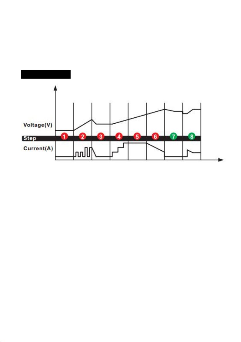
take up to eight (8) hours to complete the recovery process and will
enter to charge (8 steps charging cycle) when completed. This mode
uses a high charging voltage and may cause some water loss in WET cell
batteries. Plus, some batteries and electronics may be sensitive to high
charging voltages. To minimize risks, disconnect the battery from the
vehicle before using this mode.
Using 13.6V SUPPLY (Hold & Press)
This mode converts the charger to a constant voltage, constant current
DC power supply. When the charger is not connected with battery, it can
be used to power 12VDC devices. Prior to use, read your 12VDC device
manual to determine if it is suitable for use with this mode. As a power
supply, it can also be used to retain a vehicle’s on-board computer
settings during battery repair or replacement. 13.6V Supply Mode
provides 13.6V at 9.5A with overload protection at 10A (Max). Both
spark proof and reverse polarity protection are disabled in this mode. Do
NOT allow the positive and negative battery clamp to touch or connect
to each other as the charger could generate sparks.
Using 12V JUMP CHARGE (Press)
USE THIS MODE WITH FULL ATTENTION AS THE CHARGING CURRENT IS
20A. This mode is for 12-volt LEAD_ACID batteries only. To operate JUMP
CHARGE, the charger must be connected to a 12V battery with the
battery clamps connected. Press the Jump Charge button to begin
jumpstarting. For optimal results, allow JUMP CHARGE to complete its
5-minute charge. After 5-minute jumpcharge, the charger will
automatically enter Standby Mode, whether 100% battery level
indicator is illuminated or not, and your are ready to start your vehicle. If
unsuccessful when starting your vehicle, let the battery rest for 15
minutes and try JUMP CHARGE again. Most vehicles will start with one

7
(1) JUMP CHARGE, but larger vehicles with dual battery systems, may
require an additional JUMP CHARGE. Do not use jump charge more than
two (2) times within a 24-hour period. If two (2) jump charges cannot
successfully start your vehicle, have your battery replaced or evaluated
by a local battery store.
CHARGING STEPS
STEP 1: DIAGNOSIS (Check if battery has connected with the charger
and also check battery voltage)
STEP 2: DESULPHATION (If battery voltage is too low, programs
automatically generate pulsing current to remove sulphate, up to 5
hours)
STEP 3: ANALYSE (Check if the battery voltage reaches to the threshold
after desulphation, and charging begins if the battery voltage is OK)
STEP 4: SOFT START (Charge with echelon constant current)
STEP 5: BULK (Charge with constant maximum current until battery
voltage is reached to the threshold)
STEP 6: ABSORPTION (Provide gradually declining current charge for
maximum battery voltage)
STEP 7: ANALYSE (Test if the battery can hold charge)
STEP 8: MAINTENANCE (Continuously monitor the battery, and charging
current will intelligently adapt to the variable battery voltage)

8
BATTERY LEVEL INDICATOR
LED
Explanation
25%
The 25% Charge Red LED will slowly flash when the
battery level is less than 25%. When 25% is reached,
the LED will be solid.
50%
The 50% Charge Red LED will slowly flash when the
battery level is less than 50%. When 50% is reached,
the LED will be solid.
75%
The 75% Charge Red LED will slowly flash when the
battery level is less than 75%. When 75% is reached,
the LED will be solid.
100%
The 100% Charge Green LED will slowly flash when
the battery level is less than 100%. When 100% is
reached, the 100% Charge LED will be solid. The
25%, 50% and 75% Charge LEDs will turn off.
LED COMMUNICATION OF ABNORMAL RESULTS
No
.
LIGHT(S)
CONDITION
CAUSE(S)
SOLUTION(S)
1
Solid Red Warning!
LED
Reverse Polarity
Exchange the red and
black clamps to the
correct battery posts
2
Flashing Red
Warning! LED
1) Open-circuit
2) Dirty Battery
Posts
3) Dead Battery
1) Connect the red
and black clamps to
the battery posts
2) Clean the battery
posts
3) Replace the
battery with a new
one immediately
3
Slow flashing Red
Charging in 12V
Please do manually

9
Warning! LED
+
Corresponding
charging mode LED
Mode(s) for 24V
battery
press Mode button to
choose correct
charge mode.
CAUTION: If you
choose 12V Mode(s)
for 24V battery, the
12V battery will be
damaged!
4
Only charging
mode LED is on,
four battery level
indicator LEDs are
flashing
Overheat protection
Current reduces
when temperature in
charger is too high.
After cooling down,
charge will begin
5
Solid yellow REPAIR
LED
+
12V corresponding
charging mode LED
In 12V REPAIR mode
------
6
Solid Red Warning!
LED
+
Solid yellow SUPPLY
LED
Overload in SUPPLY
Mode (will
automatically shut
down for 30 seconds
as protection)
Disconnect the
external device
7
Quick flashing Red
Warning! LED
+
Corresponding
charging mode LED
Battery cannot store
electric charge
during charging
process
Replace the battery
with a new one
immediately
8
Only corresponding
charging mode LED
+
Four battery level
indicator LEDs are
all OFF
In Desulphation
Process
------

10
9
Red Warning! LED
light flashes 2x stop
for 3secs, 2x stop
for 3 secs…
Battery cannot be
recovered through
Desulphation
Process or Battery
cannot be recovered
through Repair
Mode
1) Replace with a new
battery
2) If battery cannot
be recovered through
Desulphation
Process, try REPAIR
Mode for recovery
10
Flashing Yellow
Warning! LED
(ONLY for 12V
lead-acid batteries)
Heavily Corroded
Battery (voltage is
less than 3V), need
Repair Mode
Replace with a new
battery or try REPAIR
Mode for recovery
NOTICE: following situation indicates that battery need to be replaced,
although there is no abnormal result LED communication.
After full charging cycle and with 100% of battery level indicator, use this
battery to start matched vehicle’s engine. If engine cannot be activated
(exclude the problem of vehicle itself), it indicates this battery has
declined storage capacity and need to be replaced or try REPAIR Mode
for recovery.
Nameplate icon description
:Class II
:For indoor use only
:Before charging, read the instructions
:Fuse

11
:Correct Disposal of this product
This marking indicates that this battery charger and batterypack should
not be disposed with other household wastes throughout the EU. To
prevent possible harm to the environment or human health from
uncontrolled waste disposal, recycle it responsibly to promote the
sustainable reuse of material resources. To return your used device,
please use the return and collection systems or contact the retailer
where the product was purchased. They can take this product for
environmental safe recycling.
WARRANTY
1) This product is warranted to the original purchaser for a period of two
(2) years from the original shipping date, to be free of defects in material
and workmanship.
2) Warranty Performance: During the above two (2) years warranty
period, a product with a defect will be replaced with a new one when
the product is returned to the manufacturer. The replacement product
will be in warranty for the balance of the original two (2) years warranty
period.
3) This warranty is void if the product has been damaged by accident, in
shipment, unreasonable use, misuse, neglect, improper service,
commercial use, repairs by unauthorized personnel or other causes not
arising out of defects in materials or workmanship.
Important safety instructions
1)This appliance is not intended for use by persons (including children)
with reduced physical, sensory or mental capabilities, or lack of
experience and knowledge, unless they have been given supervision or
instruction concerning use of the appliance by a person responsible for
their safety.
2)Children should be supervised to ensure that they do not play with the
appliance.

12
3)If the supply cord is damaged, it must be replaced by the manufacturer,
its service agent or similarly qualified persons in order to avoid a hazard.
3)The battery terminal not connected to the chassis has to be connected
first. The other connection is to be made to the chassis, remote from the
battery and fuel line. The battery charger is then to be connected to the
supply mains;After charging, disconnect the battery charger from the
supply mains. Then remove the chassis connection and then the battery
connection.
4)Do not recharging non-rechargeable batteries.
5)During charging, the battery must be placed in a well ventilated area.
Table of contents
Other Gacell Batteries Charger manuals

Gacell
Gacell SLH 19C User manual

Gacell
Gacell CT-1000 User manual

Gacell
Gacell HF1000 User manual

Gacell
Gacell CTEK MULTI US 7002 User manual

Gacell
Gacell SLC 53C User manual

Gacell
Gacell SLC 93C User manual

Gacell
Gacell C3-CHG-01 00 Series User manual

Gacell
Gacell CT-7000 User manual

Gacell
Gacell SLH 26C User manual

Gacell
Gacell ABC 600 User manual