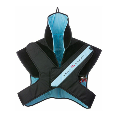
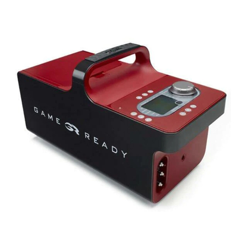
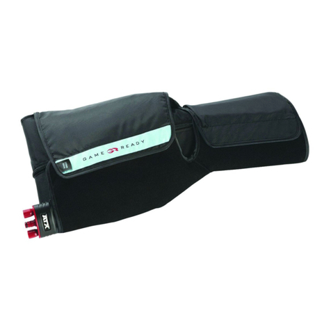
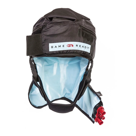
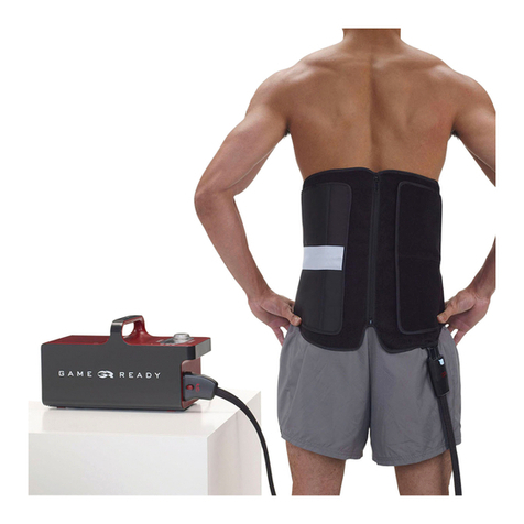
Game ready 550450 User manual

P/N 703073 Rev C CoolSystems, Inc. – Confidential & Proprietary Page 1 of 43
TECHNICAL MANUAL
GAME READY® THERAPY SYSTEM
Model Numbers:
550450 nd 550550-X2 (GR2.0)
550450-X3 nd 550550-X3 (GR2.1)
CoolSystems Inc., Effective Date: 12/23/14

TECHNICAL MANUAL
P/N 703073 Rev C CoolSystems, Inc. – Confidential Proprietary Page 2 of 43
T ble of Contents
Contents
2. INTRODUCTION ....................................................................................................................... 4
3. THEORY OF OPERATION .......................................................................................................... 5
3.1. Self-Diagnostics Checks .................................................................................................... 5
3.1.1. LCD Display ................................................................................................................ 5
3.1.2. Air Pressure Sensor “Zero” Check ............................................................................. 5
3.1.3. Air Pump Check ......................................................................................................... 5
3.1.4. Fluid Pump Check ...................................................................................................... 6
3.1.5. Temperature Sensor Check (GR2.1 only) .................................................................. 6
3.2. Air Pressure ...................................................................................................................... 6
3.3. Fluid Flow ......................................................................................................................... 7
3.4. Temperature Control ....................................................................................................... 7
4. CLEANING .............................................................................................................................. 12
4.1. Control Unit .................................................................................................................... 12
4.2. Wraps (Heat Exchangers and Sleeves) ........................................................................... 13
4.3 Connector Hose. ............................................................................................................. 14
4.4. Carry Bag ........................................................................................................................ 15
5 MAINTENANCE/ REPAIRS. .................................................................................................... 16
5.1. Filter ............................................................................................................................... 16
5.2. O-rings ............................................................................................................................ 17
5.3. Door Lid .......................................................................................................................... 18
5.4. Other Repairs ................................................................................................................. 18
5.5. Replacement Parts ......................................................................................................... 19
6. CALIBRATION / VERIFICATION .............................................................................................. 24
6.1 Pressure Verfication. ........................................................................................................... 24
6.2 Temperature Verfication. ................................................................................................... 26
6.2.1 GR 2.1 Temperature Verification. ........................................................................... 26
6.2.2. GR2.0 Temperature Verification ............................................................................ 29
6.3. Button Functionality ....................................................................................................... 30
6.4. Encoder Check (GR2.1 only) ........................................................................................... 30
CoolSystems Inc., Effective Date: 12/23/14

TECHNICAL MANUAL
P/N 703073 Rev C CoolSystems, Inc. – Confidential Proprietary Page 3 of 43
7. STORAGE ............................................................................................................................... 32
8. Product Specifications .......................................................................................................... 34
8.1. SAFETY INFORMATION ................................................................................................... 34
8.2. UL CLASSIFICATION ........................................................................................................ 34
9. Troubleshooting .................................................................................................................... 36
10. Contact Us .......................................................................................................................... 43
CoolSystems Inc., Effective Date: 12/23/14

TECHNICAL MANUAL
P/N 703073 Rev C CoolSystems, Inc. – Confidential Proprietary Page 4 of 43
1. INTRODUCTION
This manual is intended to provide technical information to customers who may benefit from
information beyond that provided in the User Manual that accompanies each Game Ready
Professional Therapy System. The Technical Manual is intended to be used by individuals who
are mechanically inclined and able to follow detailed instructions. It is not intended to REPLACE
the User Manual. The User Manuals contains complete information about the Instructions For
Use, treatment modes, Warnings, Cautions, Contraindications, and additional information
about the use of the system. Use of this manual assumes the user has read and understood the
user manual(s) and is familiar with using the Game Ready system. If you do not have a User
Manual for your system(s), contact your Game Ready distributor or Game Ready Customer
Service at 1.888.426.3732 (from outside the US call +1.510.868.2100) or visit
http://www.gameready.com/support
CoolSystems Inc., Effective Date: 12/23/14

TECHNICAL MANUAL
P/N 703073 Rev C CoolSystems, Inc. – Confidential Proprietary Page 5 of 43
2. THEORY OF OPERATION
The Game Ready System allows the user to adjust treatment time, temperature and air
pressure as desired. Both Manual and “Program Modes” are offered for convenience. The
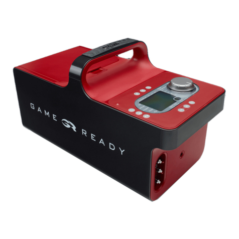
Control Unit comprises a user interface “Control Panel”, a microprocessor, multiple sensors,
Hose connection port, and a 12VDC power inlet. The following sections offer additional insight
as to how the Control Unit works.
2.1. Self-Di gnostics Checks
When pressing the power button, the Control Unit performs several Self Diagnostic
checks.
2.1.1. LCD Displ y
All segments of the LCD display are cycled on and then off during the self-test. This allows
the user to inspect the segments for function.
2.1.2. Air Pressure Sensor “Zero” Check
With the air pump off and the solenoid valve open, the air pressure transducer is checked
for an acceptable range (should be close to atmospheric pressure, or zero pressure). If
the pressure is beyond acceptable limits, an “01 error” will occur. This could be caused by
a bad pressure sensor, or if the Control Unit is hooked up to a Wrap still containing air
pressure.
2.1.3. Air Pump Check
If the Air Pressure Sensor “Zero” Check passes, the solenoid valve is closed and the air
pump turned on. If the air pressure is not greater than zero within ½ a second, an “02
error” will occur. After this test the air vent is opened and the air pump turned off.
CoolSystems Inc., Effective Date: 12/23/14

TECHNICAL MANUAL
P/N 703073 Rev C CoolSystems, Inc. – Confidential Proprietary Page 6 of 43
2.1.4. Fluid Pump Check
The coolant pump is turned on and monitored for a non-zero current. This is more of a
continuity check than a performance check. If no current is sensed, this means that the
fluid pump is not working and a “12 error” will occur.
2.1.5. Temper ture Sensor Check (GR2.1 only)
The Temperature Sensor is monitored for a “valid value”. Valid values are 28-149 degrees
F. It is intended to be a rough check of the sensor, and to prevent operation of the Control
Unit in freezing temperatures. If a valid value is not found, a “13 error” will occur.
2.2. Air Pressure
The Control Unit utilizes an air pump, a solenoid vent, and an air pressure sensor that
work together to monitor and maintain air pressure in the Wrap according to the pressure
setting used. The graph below shows a simplified illustration of the 3 pressure settings.
Air Pressure Indic tor
Depending on your software version, the air pressure bar graph will indicate either
actual pressure, or will indicate the progress of the pressure cycle. You can tell which
version you have by squeezing a Wrap in the middle of the pressure cycle. If the bar
graph is indicating actual pressure, it will show an increase from the squeezing of the
Wrap.
CoolSystems Inc., Effective Date: 12/23/14

TECHNICAL MANUAL
P/N 703073 Rev C CoolSystems, Inc. – Confidential Proprietary Page 7 of 43
Air Pressure Errors
During treatment, the Control Unit continuously monitors and adjusts air pressure. If
the air pressure falls outside of certain parameters, air pressure alarms may occur:
•06: Over Pressure Error (sensed brief period of over pressure)
•07: Under Pressure Error (did not reach top of pressure profile within expected
timeframe)
•08: Deflation Error (pressure did not vent at the bottom of the pressure profile
within the expected timeframe).
2.3. Fluid Flow
The Control Unit has a fluid pump that circulates the ice water through the system. The
fluidics circuit contains the ice box filter, a fluid pump, a flow sensing system, and either 1
or 2 temperature sensors (Reference the “Temperature Control” Section for more detail
on temperature sensing). The Flow Sensing system monitors your Control Unit for
adequate flow returning to the Control Unit.
Fluid Flow Errors: If adequate flow is not sensed, one of two flow alarms will occur. If flow
never sensed at the beginning of a treatment, the system assumes the Hose is not
connected to a Wrap, there is not enough water in the ice box, there is a blockage in the
system, or an air bubble in the fluid pump (pump priming problem). In this case, an 04
error (Dry Pump Alarm) will occur. If flow is sensed at the beginning of a treatment, it will
not call an 04 error, but will continue to monitor flow. If flow is blocked during treatment
for a long enough period of time, a 10 error (Low Flow) will occur. Also during treatment,
the fluid pump current will be monitored. If the pump current is found to be excessive, an
09 error will occur.
2.4. Temper ture Control
The Control Unit does not generate cold. The water is cooled by the ice in the ice box,
and warmed by water returning from the Wrap, using the heat of the user as a heat
source. GR2.0 and GR2.1 systems control temperature in a different manner.
CoolSystems Inc., Effective Date: 12/23/14

TECHNICAL MANUAL
P/N 703073 Rev C CoolSystems, Inc. – Confidential Proprietary Page 8 of 43
Temperature Control for GR2.1 Control Units
GR2.1 Control Units utilize a patented temperature control system. The temperature
control knob is connected to a digital encoder and allows the user to set the desired
temperature (Target Temp.). The Control unit will adjust the fluid pump speed to deliver
water from the Control Unit at a temperature close to the Target Temp. This is achieved
by using a Baffle inside the GR2.1 ice box. Water returning from the Wrap is typically
warmed by the user’s body heat. If the water is moving fast (high pump speed), it is sent
far into the ice box and readily mixes with the ice and water and cold water is drawn into
the baffles. If the water returns more slowly, it falls within the baffle walls and the water
temperature inside the baffles becomes warmer than the temperature in the rest of the
ice box. Therefore, by varying the pump speed, the temperature of the water leaving the
Control Unit may be controlled. This is all done by the Control unit automatically.
This is a significant improvement over other variable flow rate temperature control
systems. With other systems, the water leaving the Control Unit is still ice cold, and in
order to achieve a desired “Average Wrap Temperature”, much lower flow rates would be
required, which leads to significant temperature variation within the Wrap which is
undesirable.
Temperature of the water is measured at only one place in the GR 2.1 Control Units - just
before leaving the Control Unit (T1). Two different temperatures are displayed on the
Control Panel. The “Target Temperature” is the desired temperature, or temperature
“set” by the user. The “Actual Temperature” is the temperature of the water leaving the
Control Unit (T1).
The following notes regarding the GR2.1 Control Unit also may be of interest:
•When set to “full cold” the fluid pump will always pump at full speed regardless of the
water temperature.
•If the ice box runs low on ice, there may not be enough ice to achieve desired Target
Temperature.
•If the ice box is too full of water (i.e. above the return nozzle) the ability to regulate to
warmer temperatures may be limited. Always fill the Control Unit according to the
user manual and Fill Labels inside the ice box.
•When the “Play” button is pressed, water will flow at 100% until return flow is sensed
by the flow measurement system inside the Control Unit. Once return flow is sensed,
the fluid pump will modulate in order to achieve its Target Temperature.
•The maximum set point on a GR2.1 is 50°F (10°C). If warmer temperatures are desired,
less or no ice may be used, but the Control Unit will not be able to control
temperature above 50°F, and the fluid pump will pump at full speed during treatment.
CoolSystems Inc., Effective Date: 12/23/14
TECHNICAL MANUAL
P/N 703073 Rev C CoolSystems, Inc. – Confidential Proprietary Page 9 of 43
GR2.1 Temperature Control Block Diagram
CoolSystems Inc., Effective Date: 12/23/14
TECHNICAL MANUAL
P/N 703073 Rev C CoolSystems, Inc. – Confidential Proprietary Page 10 of 43
Temperature Control for GR2.0 Control Units
GR2.0 Control Units use a mixing valve connected to the temperature control knob. A
ratio of cold water is mixed from the ice box and the warmer return water as shown
below. At “Full Cold”, the pump is drawing 100% of its water from the ice box. At “Full
Warm” the pump is drawing 100% of its water directly from the Wrap, recycling the
return water which continues to be warmed by the body. At knob positions in between,
the pump draws water from both the ice box and the Wrap, proportional to the position
of the knob. Since the water temperature depends on the ice box temperature, return
water temperature (heat load), and knob position, the temperature may drift over time,
and the knob position will not always yield the same temperature each time.
Temperature of the water is measured in two places in the GR 2.0 Control Units;
referencing the figure below, the temperature is measured just before leaving the
Control Unit (T1), and upon returning from the Wrap, back into the Control Unit (T2).
Two different temperatures are displayed on the Control Panel. The “Coldest Wrap
Temp” is the temperature of the water leaving the Control Unit. The “Average Wrap
Temp” is the average of the water leaving the Control Unit (T1) and temperature of the
water returning to the Control Unit (T2).
The following notes regarding the GR2.0 Control Unit also may be of interest:
•The fluid pump will always run at full speed, regardless of the temperature setting.
•If the ice box runs low on ice, there may not be enough ice to reach the desired
temperature.
•When starting a treatment with a GR2.0 Control Unit, it is best to start with the knob
at full cold. This ensures that water is being drawn from the ice box and reduces the
chance of an air bubble entering the fluid pump and stopping fluid flow. If this
happens, an “04 error” (Dry Pump Alarm) will occur. Reference the trouble shooting
section of the manual for advice on clearing this error.
•There is no maximum temperature setting on a GR2.0. If set to full warm, the water
will not draw water from the ice box, and will continue to recycle return water from
the Wrap which is continuously warmed by the user’s body heat, and the water
temperature in the Wrap could eventually reach body temperature.
CoolSystems Inc., Effective Date: 12/23/14
TECHNICAL MANUAL
P/N 703073 Rev C CoolSystems, Inc. – Confidential Proprietary Page 11 of 43
GR2.0 Temperature Control Block Diagram
CoolSystems Inc., Effective Date: 12/23/14
TECHNICAL MANUAL
P/N 703073 Rev C CoolSystems, Inc. – Confidential Proprietary Page 12 of 43
3. CLEANING
3.1. Control Unit
The exterior of the Control Unit and the visible interior surfaces of the ice box can be
cleaned with warm water and mild soap, being careful to wipe with a damp cloth to
remove any soap residue.
C ution: The Control Unit is not waterproof. Do not apply a direct stream of water onto
or submerge the Control Unit. Do not allow fluid to pool on the surface of the face plate
of the unit. Fluid left to pool on the face plate may accumulate under the surface and
corrode the connections.
Disinfection may be performed using CaviWipes™ or the equivalent (CoolSystems has
tested only CaviWipes). To ensure maximum effectiveness and compliance with
applicable OSHA, CHAP or Joint Commission requirements, follow the manufacturer’s
recommendations for tuberculocidal activity. Cavicide also leaves a residue that, after it
has dried, should be wiped off with a clean damp cloth.
CaviWipes may be purchased from numerous sources including the manufacturer’s
website at www.metrex.com.
Procedure:
•Follow the manufacturer’s instructions and precautions for the cleaning agent
•Clean the Control Unit of visible dirt and debris
•To disinfect, wipe down all surfaces of the Control Unit so that the surfaces remain
visibly wet for 3 minutes (at room temperature) or per manufacturer’s instructions
•After 3 minutes, wipe the treated surfaces with a clean damp cloth to remove the
disinfectant residue
•Allow the Control Unit to dry thoroughly before returning it to service or storing it in
the bag
•If not returning the Control Unit to service right away, leave the lid to the ice box
open to prevent mold/mildew formation
•The Control Unit should be disinfected whenever it is used on more than one
patient, prior to being used by subsequent patients
CoolSystems Inc., Effective Date: 12/23/14
TECHNICAL MANUAL
P/N 703073 Rev C CoolSystems, Inc. – Confidential Proprietary Page 13 of 43
Do Not Use:
•Quaternary Ammonium (such as Virex)
•Phenolic-based disinfectants (such as Amphyl).
•Any solvent-based cleaners on the Control Unit. Doing so will damage the plastics
and will void the warranty.
•Abrasive materials to clean the Control Unit. Doing so will damage the plastics and
will void the warranty.
•Hydrogen Peroxide
3.2. Wr ps (He t Exch ngers nd Sleeves)
The Wraps are non-sterile products made up of outer Sleeves with a “hook and loop”
closure (similar to Velcro®) and zippered pockets into which Heat Exchangers (the inner
component through which the air and water flow) are inserted. Both may be cleaned of
dirt and other biological soil for reuse or discarded, but neither can be sterilized.
Regul r M inten nce/Cle ning
•Remove Heat Exchanger from Sleeve after each use to limit condensation collecting
inside sleeve.
•The Heat Exchanger is made of fabric and, if it becomes soiled, it may be cleaned with
Steri-Fab® (www.sterifab.com) per the manufacturer’s instructions or it may be
discarded. The Heat Exchanger may also be cleaned with a soft cloth and warm soapy
water followed by thorough rinsing and drying of the fabric.
•The Sleeve is intended for single patient use in the hospital setting and limited multi-
patient use in outpatient settings with protected Sleeve-skin contact. Additional
sleeves may be purchased by contacting Customer Service.
•For limited multi-patient use in outpatient settings, the Sleeve may be cleaned by
spraying it down with Steri-Fab and/or washing on the gentle cycle in a standard
washing machine. The Sleeve may be used and washed in this way for approximately
3 months or approximately 200 open/close cycles and 3-4 machine washings. After
that the Sleeve may begin to lose pull strength on the hook loop closure and should
be replaced.
CoolSystems Inc., Effective Date: 12/23/14

TECHNICAL MANUAL
P/N 703073 Rev C CoolSystems, Inc. – Confidential Proprietary Page 14 of 43
Mildew
Condensation occurs naturally on the cold surface of the heat exchanger. Constant use
and immediate storage of the Game Ready Wraps can cause mildew growth in some
circumstances. The Sleeve portion of the Wrap is meant to be a protective barrier for the
Heat Exchanger that can be removed and discarded or cleaned (as described above). The
Sleeve also has a coating on the inside that locks in moisture. Like a wet umbrella, it
needs to be allowed to dry or wiped down before storing. Failure to do so can result in
mildew formation on the interior of the sleeve or on the Heat Exchanger.
If mildew does occur and the choice is to clean rather than discard:
•The Heat Exchanger may be cleaned carefully with Steri-Fab (noted above), which is
also a mildewcide, following the manufacturer’s instruction.
•The Sleeve may be washed, thoroughly dried and sprayed with Steri-Fab and again
allowed to dry thoroughly before inserting a Heat Exchanger.
Mildew stains cannot be removed from the Sleeve or the Heat Exchanger. They can be
cleaned, but the stain will remain. We recommend replacing the affected components
and diligent preventative care to prevent future mildew growth. The following are some
suggestions for avoiding mildew propagation.
•Drain most of the residual water from the Wrap following use by leaving it connected
to the Control Unit for 5-10 minutes. This drain action can be enhanced by raising the
height of the Wrap above the Control Unit as much as possible.
•Separate the Sleeve and the Heat Exchanger to dry them independently.
•Open the Sleeve and its zippered pocket as much as possible and dry off the interior
blue surface. Leave open to thoroughly dry for as long as practical.
•Lay the Heat Exchanger flat and wipe dry and hang or lay flat on a towel to allow to
dry.
3.3. Connector Hose
•The Connector Hose braided nylon cover may be cleaned with Steri-Fab and the
plastic connectors may be cleaned with warm soapy water. The connectors may also
be disinfected with CaviWipes.
•A PVC-covered Hose (plastic covering over the braided fabric for easier
cleaning/disinfection) is available and may be ordered through Customer Service.
(Game Ready Part # 570304)
CoolSystems Inc., Effective Date: 12/23/14

TECHNICAL MANUAL
P/N 703073 Rev C CoolSystems, Inc. – Confidential Proprietary Page 15 of 43
Do Not Use:
•Quaternary Ammonium (such as Virex).
•Phenolic-based disinfectants (such as Amphyl).
•Any solvent based cleaners on the Connector. Doing so will damage the plastics and
will void your warranty.
•Abrasive materials to clean the Connector. Doing so will damage the plastics and will
void your warranty.
•Any petroleum based lubricants on the Connector. Doing so may damage the O-rings
and will void your warranty.
3.4. C rry B g
The Carry Bag should be cleaned using a soft cloth or brush and, if needed,
decontaminated with Steri-Fab according to the manufacturer’s instructions. Be sure to
test any cleaner on a small portion of the Bag to make sure that it will not damage the
Bag.
CoolSystems Inc., Effective Date: 12/23/14

TECHNICAL MANUAL
P/N 703073 Rev C CoolSystems, Inc. – Confidential Proprietary Page 16 of 43
4. MAINTENANCE / REPAIRS
The following section contains certain maintenance and repairs that may be performed by
users. While the maintenance and repair instructions are noted below, always be sure to use
the instructions included with the replacement parts for additional information, cautions and
warnings.
4.1. Filter
The Ice Box Filter helps protect against debris from damaging the fluid pump, and is found
inside the Ice Box. If the filter becomes dirty or clogged, water flow thru the system will
be restricted. It is recommended to inspect the ice box filter approximately once every 3
months or as needed:
Model 550550-X3 (GR2.1)
•Remove the filter by pressing the tabs together and pulling straight out.
•Clean the filter by rinsing it thoroughly under warm running water, or blowing with air
thru filter mesh from the inside.
•Replace, orienting the Tab at the top, and pressing into place, ensuring tabs snap into
place.
Model 550550-X2 (GR2.0)
•Remove the filter by rotating it counter-clockwise. If needed, a ¾” deep socket
wrench may be used.
•Clean the filter by rinsing it thoroughly under warm running water, or blowing with air
thru filter mesh from the inside.
•Reinsert the filter “finger tight”. Avoid cross-threading.
CoolSystems Inc., Effective Date: 12/23/14

TECHNICAL MANUAL
P/N 703073 Rev C CoolSystems, Inc. – Confidential Proprietary Page 17 of 43
Replacement filters may be obtained by contacting Game Ready Customer Service. Refer
to the “Replacement Parts” section and order the filter associated with your model
number.
4.2. O-rings
If the Hose or Wrap connections get “sticky” or hard to connect, they may require
lubrication. Apply a light amount of silicone lubricant to the O-rings as needed. (In an
emergency, water may help.) Note: To prevent possible damage to the O-rings, use only a
silicone lubricant (i.e. not a petroleum based lubricant). This may be purchased by
contacting your Game Ready Distributor or Game Ready Customer Service and ordering
Silicone Pump Spray – (G me Re dy P rt # 573201).
The following alternate silicone sprays have also been successfully tested for use on the
O-rings:
•DuPont Teflon Silicone Spray (DuPont Part # DS0614101)
McMaster Carr Part # 8710T22
www.mcmaster.com
•3M Silicone Spray (3M ID#62-4678-4930-3)
McMaster Carr Part # 31155K36
www.mcmaster.com
or
3M e-store
www.3mestore.com
If the O-rings are cracked or damaged (i.e. leaking), they may be replaced using one of our
O-ring replacement kits (Reference the Replacement arts section):
CoolSystems Inc., Effective Date: 12/23/14

TECHNICAL MANUAL
P/N 703073 Rev C CoolSystems, Inc. – Confidential Proprietary Page 18 of 43
P nel Mount O-Ring Wr p Connector O-Ring Hose Connector O-Ring
4.3. Door Lid
If the Ice Box door lid becomes damaged or broken, it may be replaced by ordering an Ice
Box Lid Replacement Kit. Refer to the “Replacement Parts” section for the part number
and description. Abbreviated instructions are shown below.
Removal Installation
4.4. Other Rep irs
Other than those listed above, no product repairs should be performed by the user. If
your Game Ready System requires repair service, please contact your Game Ready
Distributor or Game Ready Customer Service. Opening the Control Unit case will void the
warranty.
1
2
3
1
2
3
CoolSystems Inc., Effective Date: 12/23/14

TECHNICAL MANUAL
P/N 703073 Rev C CoolSystems, Inc. – Confidential Proprietary Page 19 of 43
4.5. Repl cement P rts
The following is a list and description of replacement parts and test fixtures that may be
purchased thru Game Ready. Please contact your Game Ready Distributor or Game Ready
Customer Service for more information.
Part # Description
Instructions
Part #
503512 Panel Mount Connector O-Ring Replacement Kit with Tool
703793
503513 Panel Mount Connector O-Ring Replacement without Tool
703793
573208 Wrap Connector O-Ring Replacement Kit with Tool
704094
CoolSystems Inc., Effective Date: 12/23/14

TECHNICAL MANUAL
P/N 703073 Rev C CoolSystems, Inc. – Confidential Proprietary Page 20 of 43
573209 Wrap Connector O-Ring Replacements without Tool
704094
573217 Hose Connector O-Ring Replacement Kit with Tool
704134
573218 Hose Connector O-Ring Replacements without Tool
704134
573214 3-Port Connector Replacement Kit (Blue Button)
702448
CoolSystems Inc., Effective Date: 12/23/14
Other manuals for 550450
1
This manual suits for next models
3
Table of contents
Other Game ready Medical Equipment manuals

Game ready
Game ready GRPro 2.1 User manual

Game ready
Game ready ATX C-T Spine User manual

Game ready
Game ready ATX TRAUMATIC AMPUTEE Operating manual

Game ready
Game ready GRPro 2.1 Operating manual

Game ready
Game ready Med4 Elite User manual

Game ready
Game ready ATX C-T SPINE WRAP Operating manual

Game ready
Game ready ATX SHOULDER WRAP Operating manual

Game ready
Game ready ATX COOLING VEST Operating manual

Game ready
Game ready ATX BACK WRAP Operating manual

Game ready
Game ready ATX HAND Operating manual