GAS GC-IMS-SILOX User manual

G.A.S. Gesellschaft für
analytische Sensorsysteme mbH
GC-IMS-SILOX
USER MANUAL

1
GC-IMS-SILOX – User Manual
Version 1.4.0, March 2021
All data, texts, designs, images and other elements used in this user manual are
protected by copyright law. Any infringement may be subject to legal action.
Passing it on to third parties and producing copies of any kind or form –on the
whole or in parts - is not permitted without written agreement of G.A.S. Any
infringement may be subject to legal action.
G.A.S. reserves the right to realize technical changes to the product without
explicitly mentioning them.
CE-Marking according to:
International Standard EN ISO 17050-1:2004
European Union Low Voltage Directive 2006/95/EC
European Union Electromagnetic Compatibility Directive 2004/108/EC
© Copyright 2015-2021
G.A.S. Gesellschaft für analytische Sensorsysteme mbH
44227 Dortmund - Germany
All Rights Reserved.

2
Table of Content
1Preface..................................................................................5
1.1 Symbols Used in this User Manual ...........................................5
1.2 Notation for Describing Dialogs and Elements in Dialogs ................6
1.3 Liability and Guarantee ......................................................6
1.4 Return and Disposal ...........................................................7
1.5 Packing..........................................................................7
1.6 Transport .......................................................................8
1.7 Software Updates..............................................................8
1.8 Contacting G.A.S. .............................................................8
2Safety ................................................................................. 10
2.1 Intended Usage Only ........................................................ 10
2.2 Responsibilities of the Operator........................................... 10
2.3 Ionization Source ............................................................ 11
2.4 Explosion Protection ........................................................ 11
2.5 Protection from High Voltage.............................................. 12
3Scope of Supply and Storage Conditions ......................................... 13
3.1 Scope of Supply .............................................................. 13
3.2 Storage Conditions .......................................................... 14
4Cleaning of the Housing and Maintenance ....................................... 15
4.1 Cleaning of the Housing .................................................... 15
4.2 Maintenance.................................................................. 15
5Intended Use and Working Principle.............................................. 16
5.1 Intended Use ................................................................. 16
5.2 Calculating Concentrations ................................................ 16
5.3 Working Principle and Internal Gas Flow................................. 18
6Workflow: Physical Setup .......................................................... 21
6.1 Housing of the Device....................................................... 21
6.2 Device Type/Serial Number Plate on the Rear Side .................... 23
6.3 Unpacking, Placement and Connections ................................. 24
7Workflow: Initial Operation / Cleaning .......................................... 29
7.1 Using the Cleaning Mode ................................................... 29

3
7.2 Workflow ..................................................................... 29
8Device Parameters During Measurements and Standby ........................ 32
8.1 Introduction .................................................................. 32
8.2 Values ......................................................................... 32
9Workflow: Single Manual Measurement .......................................... 33
9.1 Introduction .................................................................. 33
9.2 Workflow ..................................................................... 34
10 Workflow: Manual Calibration ..................................................... 38
10.1 Introduction .................................................................. 38
10.2 Workflow ..................................................................... 38
11 Workflow: Running Automatic Measurements................................... 42
11.1 Introduction to the Interval Mode ........................................ 42
11.2 Workflow ..................................................................... 43
12 Workflow: Current Loop Setup .................................................... 49
12.1 Introduction .................................................................. 49
12.2 Electrical Interface ......................................................... 50
12.3 Configuring the Current Loop.............................................. 50
13 Workflow: Tag Lists ................................................................. 53
13.1 Introduction .................................................................. 53
13.2 Creating and Editing Tag Lists............................................. 54
13.3 Usage.......................................................................... 57
13.4 Exporting Tag Lists .......................................................... 59
13.5 Importing Tag Lists.......................................................... 62
14 Workflow: File Transfer Setup .................................................... 66
14.1 Overview...................................................................... 66
14.2 Connecting to a Server in a LAN .......................................... 68
15 Workflow: PDF Reports - Setup and Usage...................................... 74
15.1 Introduction .................................................................. 74
15.2 Workflow ..................................................................... 76
16 Workflow: Firmware Upgrade ..................................................... 80
16.1 Introduction .................................................................. 80
16.2 Workflow ..................................................................... 81
17 Graphical User Interface ........................................................... 84
17.1 Introduction .................................................................. 84

4
17.2 Start Page..................................................................... 85
17.2.1 Overview ............................................................ 85
17.2.2 Results View ........................................................ 87
17.2.3 Scope View.......................................................... 88
17.3 MEA Mode Start Dialog ...................................................... 89
17.4 Calibration Mode Start Dialog ............................................. 90
17.5 Substances and the Substance Calibration Dialog ...................... 91
17.6 Interval Mode Start Dialog ................................................. 93
17.7 Date and Time Input Dialogs ............................................... 95
17.8 Status Bar..................................................................... 97
17.9 Substances Page ............................................................. 99
17.10 System Page .................................................................100
17.10.1 System Page Info Tab............................................. 101
17.10.2 System Page Plan Tab ............................................102
17.10.3 System Page Settings Tab........................................ 103
17.10.4 System Page Transfer Tab .......................................107
17.10.5 The System Page Modes Tab ....................................109
17.11 Current Loop Settings Dialog .............................................110
17.12 Log Messages Dialog........................................................111
17.13 IP Address Input Dialog ....................................................112
17.14 Text Input Dialog ........................................................... 113
17.15 Number Input Dialog .......................................................113
18 Tag Lists File Formats.............................................................. 115
18.1 Overview.....................................................................115
18.2 CSV Format Specification..................................................115
18.3 JSON Format Specification ................................................116
19 Technical Specifications........................................................... 118
19.1 Measurement Ranges....................................................... 118
19.2 Device ........................................................................119
19.3 Current Loop Interface ....................................................121
19.4 Consumables ................................................................121
19.5 Ionization Source Specifications.......................................... 122
19.6 Modbus TCP Specification .................................................123
20 Calculating of silicon ’Total Si’ and silica ’Total SiO2’ in GC-IMS-SILOX ... 132
5
1Preface
1.1 Symbols Used in this User Manual
Symbol
Description
Danger
This symbol marks paragraphs that describe situations that
can potentially damage the device.
Danger –Radioactive Radiation
This symbol marks paragraphs that describe potential
dangers and damage due to exposure to radioactive
radiation.
Danger –Explosive Substances
This symbol marks paragraphs that describe potential
dangers and damage due to explosions.
Danger –High Voltage
This symbol marks paragraphs that describe potential
dangers to life and health due to electric current.
Danger - Hot Surface
This symbol marks paragraphs that describe situations in
which surface parts of the device can heat up to a point
where touching it or bringing objects close to it may be
hazardous.
Important
This symbol marks paragraphs that describe important
instructions or information that may prevent the operator
from making common mistakes.
6
1.2 Notation for Describing Dialogs and Elements in
Dialogs
Example:
System ›Connections ›LAN File Transfer ›Settings…›Test Connection
Describe the logical path for arriving in a particular dialog or at an element in
a dialog. In this example the path starts with the System page. On that page
the Connections page must be selected. On that page in the LAN File Transfer
row the button Settings… must be selected and in that dialog the button Test
Connection must be selected.
Example:
Gas Out, S-Free
Casing socket names, choice menu elements etc. are marked in this way.
1.3 Liability and Guarantee
This user manual describes the safe and proper handling of the device.
Usage other than described in this manual may damage the device
and/or harm persons involved.
Do not use the device for other purposes. Damages due to misuse are
not covered by the guarantee. Such damage claims will be rejected.
This user manual should be available to all personnel operating the device.

7
Follow the safety instructions in this manual and the national and/or local rules
and general safety regulations regarding the prevention of accidents at all
times.
Before starting to operate the device read the manual completely and
thoroughly. Make sure that all personnel operating the device understand the
instructions described.
G.A.S. does not assume any liability for damages resulting from neglect or
ignorance of the instructions in this manual or provided in other ways by G.A.S.
The graphics in this user manual are schematic and may differ from the actual
conditions. The firmware and PC software screen shots in this user manual may
slightly differ from the actual conditions.
The actual scope of supply might differ due to customization. For further
information please contact G.A.S.
1.4 Return and Disposal
For an appropriate disposal, the device and the associated equipment must be
returned to G.A.S. or to a third party authorized by G.A.S.
1.5 Packing
If no return agreement regarding the packing was agreed upon dispose the
packaging material always in an environmentally friendly way and according to
valid local regulations. If necessary, ask a recycling company.
8
1.6 Transport
To prevent damages to the equipment it should be moved only in the provided
carrying case.
Protective caps should be put on gas sockets in case the device is
stored or transported.
1.7 Software Updates
To receive information on available updates for the components of the system
please contact G.A.S. Gesellschaft für analytische Sensorsysteme mbH. If there
are any updates customers will be contacted by G.A.S. Gesellschaft für
analytische Sensorsysteme mbH as soon as the updates are available. Users will
be provided with information about the changes and instructions for executing
the updates.
1.8 Contacting G.A.S.
For questions concerning G.A.S. products a customer service is available:

9
G.A.S. Gesellschaft für analytische Sensorsysteme mbH
Otto-Hahn-Straße 15
44227 Dortmund
Germany
Phone: +49 (0) 231 / 97 42 - 65 50
Fax: +49 (0) 231 / 97 42 - 65 55
The telephone hotline is available from Monday to Friday from 9:00 to 16:00
hours. In urgent cases or if you use fax or email please provide a telephone
number for callbacks.

10
2 Safety
2.1 Intended Usage Only
Usage other than described in this manual may damage the device
and/or harm persons involved. Do not use the device for other
purposes. Damages due to misuse are not covered by the guarantee.
Such damage claims will be rejected.
2.2 Responsibilities of the Operator
The device should only be operated in a perfect technical condition. Before
putting the device into operation the condition of the device and its equipment
must be checked. The information and instructions provided in this manual must
be followed at all times.
Besides the instructions provided in this manual the local rules for the
prevention of accidents, general safety regulations - valid for the area of
application of the device - as well as the valid environment protection
regulations must be considered and respected.
Responsibilities of the involved persons regarding installation, operation,
maintenance and cleaning must be made clear.
Only authorized and trained personnel may operate the equipment. The
operators must know potential dangers and how to avoid them and should be
regularly trained on safety procedures and environmental protection
regulations.

11
Persons under the influence of drugs or alcohol must not operate the device.
Any changes to the equipment, which may endanger the operators must be
reported immediately to the operators and any person handling it.
2.3 Ionization Source
The device contains a Tritium radioactive ionization source of 300 MBq (Below
exemption limit according to EURATOM Directive 96/26).
Do not open the device! Do not try to repair any internal malfunctions
of the device! Internal malfunction recovery, repairs and any
maintenance work may only be carried out by G.A.S. or by personnel
authorized by G.A.S.
2.4 Explosion Protection
The device is not certified for deployment in areas with explosive gas/air
mixtures or other explosive substances.
Do not deploy the device in areas exposed to explosive substances or
mixtures.

12
2.5 Protection from High Voltage
Exercise great care in handling current-carrying parts like the power
supply cord. Do not get directly in touch with current-carrying parts.
Do not open the housing. Do not use damaged parts.

13
3Scope of Supply and Storage
Conditions
3.1 Scope of Supply
Ensure that you have received the full scope of supply. If there is any part
missing, please contact G.A.S. immediately.
Standard Scope of Supply
Device
Power Supply
Power Supply Cable
Gas tubes (6 x 2 m) with 3mm Swagelok Connectors
Drift Gas / Carrier Gas Adapter with 3mm Swagelok Connectors
Sample Gas Bypass Adapter with 3mm Swagelok Connectors
D-Sub Plug, Male, Wireable for Current Loop Connection
Moisture Trap
Device User Manuals
Software-CD with IMScontrol TFTP-Server
Document - Technical Approval Certificate
Document - Analytical Approval
Document - Declaration of Conformity
Document - Radiation Source Certificate
14
Optional Items
Large Moisture Trap
Transport Case
Notebook PC for direct file transfer
3.2 Storage Conditions
Check the storage conditions regularly
Storage Conditions
When not in use store the equipment in the supplied casing
Prevent unauthorized access
Do not store outside
Protect the equipment from moisture and dust
Put protective caps on all gas sockets of the device and the molecular sieve
Avoid mechanical vibrations
Do not expose the equipment to aggressive substances
Protect the equipment from direct sun light
Storage temperature: 15 to 40 °C
Relative Air Humidity: Max 60 %
15
4Cleaning of the Housing and
Maintenance
4.1 Cleaning of the Housing
Regular use of the device requires periodic cleaning.
Clean the outside of the device casing only with a dry or slightly damp
cloth. Do not use cleaning agents that contain solvents, acids or bases.
4.2 Maintenance
Natural aging and the wear of certain components of the equipment require
regular cleaning and maintenance.
The recommended maintenance interval is 12 months.
Maintenance of the equipment must be carried out by G.A.S. or
personnel authorized by G.A.S.
Please contact G.A.S. 6-8 weeks in advance to optimize the turn-
around time!
16
5Intended Use and Working
Principle
5.1 Intended Use
The intended use of the GC-IMS-SILOX device is the measurement of siloxane
concentrations in biogas from landfills, digestors and sewage.
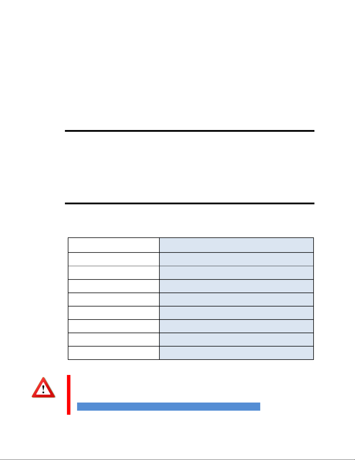
5.2 Calculating Concentrations
The device can measure siloxanes within the following concentration ranges:
Substance
Measurement Range
Siloxane –L2
Up to 10 mg/m³ - Standard 0.03 to 2.0 mg/m3
Siloxane –D3
Up to 10 mg/m³ - Standard 0.03 to 2.0 mg/m3
Siloxane –L3
Up to 10 mg/m³ - Standard 0.03 to 2.0 mg/m3
Siloxane –D4
Up to 10 mg/m³ - Standard 0.03 to 2.0 mg/m3
Siloxane –L4
Up to 10 mg/m³ - Standard 0.03 to 2.0 mg/m3
Siloxane –D5
Up to 10 mg/m³ - Standard 0.03 to 2.0 mg/m3
Siloxane –L5
Up to 10 mg/m³ - Standard 0.03 to 2.0 mg/m3
TMSOL
Up to 10 mg/m³ - Standard 0.03 to 2.0 mg/m3
The actual ranges may differ and may be customized to specific
requirements. They are displayed in the Substance Calibration Dialog.
→17.5 Substances and the Substance Calibration Dialog
17
When the calculated concentration value exceeds the respective maximum
value MaxVal it is displayed as “›MaxVal”.
When the calculated concentration value is below the respective minimum value
it is displayed as “n.d.”standing for “not detected”.
The concentration value of compound substances like Total Siloxanes is
derived from base substances (L2, L3, …). When one or more base
substance concentrations exceed their concentration ranges the value
for the compound substance is derived from the limits.
When for all base substances (L2, L3, …) a “n.d.” is calculated the
result for the compound substances is “n.d.” as well.
20 Calculating of silicon ’Total Si’ and silica ’Total SiO2’ in GC-IMS-
SILOX
18
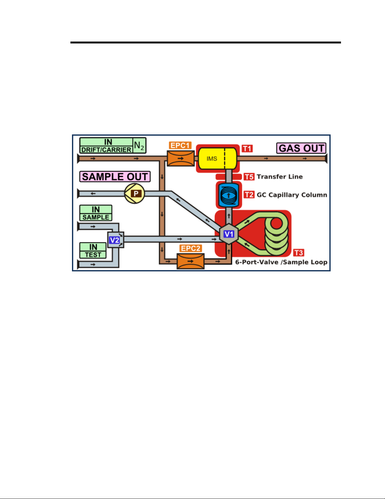
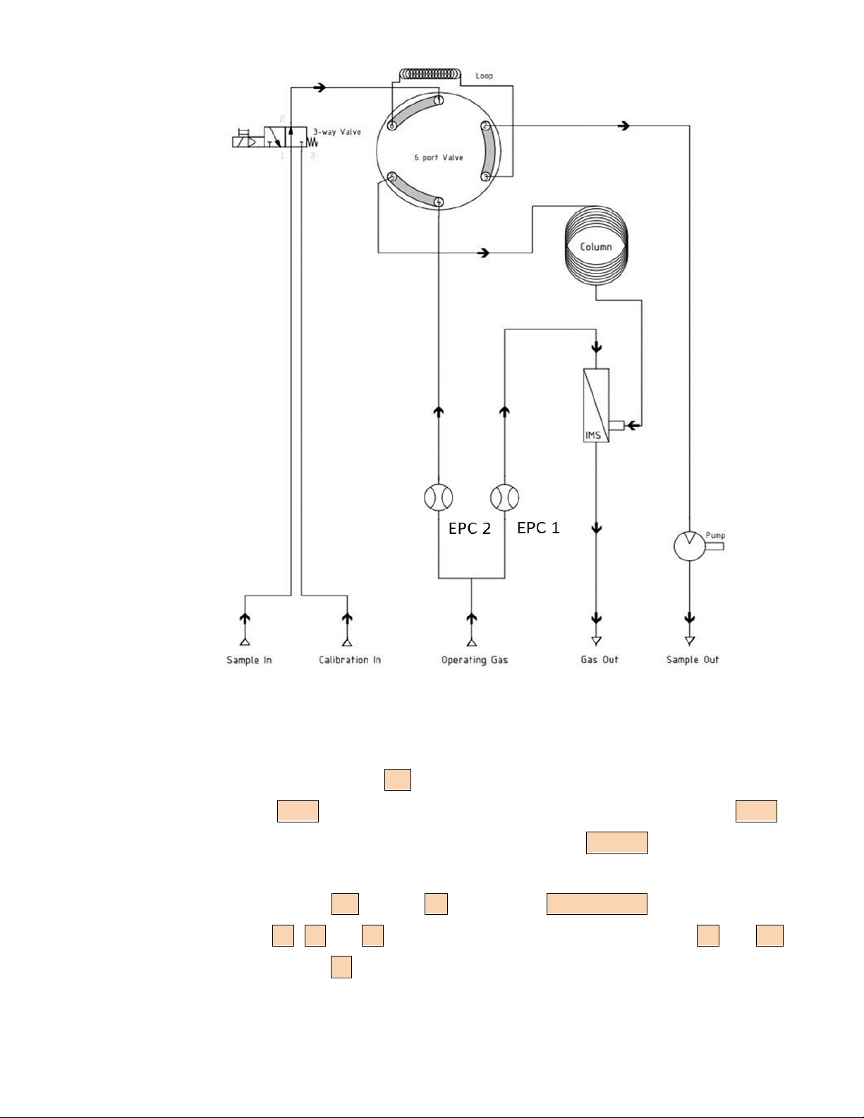
5.3 Working Principle and Internal Gas Flow
The schematics below show the main elements of the gas flow system of the
device. The system consists of a gas chromatograph (GC) using a capillary
column coupled to an ion mobility spectrometer (IMS).
For displaying the plan on the device see 17.10.2 System Page Plan
Figure 1: Device Plan
19
Figure 2: Flow-chart
The drift gas flow to the IMS sensor is controlled by the electronic pressure
control unit EPC1. The carrier gas flow to the column is controlled by EPC2.
Carrier gas and drift gas leave the device through the Gas Out outlet at the rear
side of the device, which should be connected to an appropriate waste gas
ventilation system. IMS sensor, GC column and 6-Port-Valve with sample loop
are heated (T1, T2 and T3 respectively). The transfer line between GC and IMS
sensor is heated by T5.
Table of contents
Other GAS Analytical Instrument manuals


Popular Analytical Instrument manuals by other brands

Agilent Technologies
Agilent Technologies 16702B installation guide

Dostmann Electronic
Dostmann Electronic LM 100 Instructions for use

Eclipse Combustion
Eclipse Combustion EGA4 instruction manual

Sparky Group
Sparky Group UDD 16 Original instructions

Red Technology
Red Technology CB-1005 user manual

Storz
Storz OR1 .avm installation instructions


SICK
SICK MCS300P technical information

Vividia
Vividia YE-4-8015 user manual

Pickering Laboratories
Pickering Laboratories Pinnacle PCX Operator's manual

Calculated Industries
Calculated Industries LaserDIMENSIONMASTER 3336 user guide

SonTek
SonTek ADP Software manual

Eddyfi Technologies
Eddyfi Technologies INUKTUN MINIMAG user manual