Storz OR1 .avm User manual

Installation instructions
OR1 .avm
Rel. 1.4
en

Copyright ©
All product illustrations, product descriptions, and texts are the intellectual property of
KARLSTORZSE&Co.KG.
Their use and reproduction by third parties require the express approval of KARLSTORZSE&Co.KG.
All rights reserved.
03-2023

Table of contents
Installation instructions • OR1 .avm • PFU293_EN_V3.0_03-2023_II_CE-MDR 3
Table of contents
1 General information ......................................................................................................................... 5
1.1 Reading the installation instructions .......................................................................................... 5
1.2 Other applicable documents...................................................................................................... 5
1.3 Scope......................................................................................................................................... 5
1.4 General signs and symbols........................................................................................................ 5
1.5 Description of warning messages.............................................................................................. 6
1.6 Contact address......................................................................................................................... 6
2 Safety and warning .......................................................................................................................... 7
2.1 Serious incidents........................................................................................................................ 7
2.2 Correct handling and product testing ........................................................................................ 7
2.3 Product not clean....................................................................................................................... 7
2.4 Risk of explosion and fire........................................................................................................... 7
2.5 Combination with other components......................................................................................... 8
2.6 Dangers from electrical current.................................................................................................. 8
2.7 Damage due to ingress of liquid in electrical components........................................................ 9
2.8 Observing ambient conditions ................................................................................................... 9
2.9 Electromagnetic interference ..................................................................................................... 9
2.10 Failure of products ..................................................................................................................... 9
2.11 Data transfer .............................................................................................................................. 9
3 Product description ......................................................................................................................... 10
3.1 Description of function............................................................................................................... 10
3.2 Product overview ....................................................................................................................... 10
3.3 Possible combinations ............................................................................................................... 11
3.4 Technical specifications............................................................................................................. 12
3.5 Symbols employed .................................................................................................................... 13
3.5.1 Symbols on the packaging ........................................................................................... 13
3.5.2 Symbols on the product ............................................................................................... 15
3.5.3 Symbols on the type plate ............................................................................................ 15
3.6 Ambient conditions .................................................................................................................... 16
4 Preparation ....................................................................................................................................... 17
4.1 Unpacking the product .............................................................................................................. 17
4.2 Setting up the product ............................................................................................................... 17
4.3 Connecting the product ............................................................................................................. 17
4.3.1 Connecting the OR1 .avm to AIDA ............................................................................... 18
4.3.2 Connecting the audio cabling....................................................................................... 19
4.3.3 Connecting the HIVE router .......................................................................................... 20
5 Installation and commissioning ...................................................................................................... 22
5.1 Pairing with AIDA ....................................................................................................................... 22
5.1.1 Activating routing.......................................................................................................... 22
5.1.2 Setting Windows Time Service ..................................................................................... 23
5.1.3 Connecting OR1 .avm with AIDA.................................................................................. 24
5.1.4 Activating remote service ............................................................................................. 25
5.2 Configuring the system .............................................................................................................. 25
5.2.1 Configuring streaming .................................................................................................. 26
5.2.2 General settings............................................................................................................ 29
5.2.3 Selecting sources ......................................................................................................... 30

Table of contents
Installation instructions • OR1 .avm • PFU293_EN_V3.0_03-2023_II_CE-MDR 4
5.2.4 Selecting targets........................................................................................................... 31
5.2.5 Connecting the room camera ....................................................................................... 31
5.2.6 Forbidden routes .......................................................................................................... 32
5.2.7 Setting up the SCENARA connection........................................................................... 33
5.2.8 Pre-configuration .......................................................................................................... 34
5.3 Performing a master reset.......................................................................................................... 35
5.3.1 Reading out log files ..................................................................................................... 38
5.3.2 Analyzing log files ......................................................................................................... 39
5.4 Updating the system.................................................................................................................. 39
5.4.1 Manual upload .............................................................................................................. 40
5.4.2 Automatic upload.......................................................................................................... 43
5.4.3 Starting the system update........................................................................................... 43
5.5 PKI certificates ........................................................................................................................... 44
5.5.1 Connecting an iOS-enabled smartphone ..................................................................... 45
5.5.2 Certifying the product ................................................................................................... 45
5.5.3 Troubleshooting............................................................................................................ 48
6 Maintenance, servicing, repairs, and disposal .............................................................................. 53
6.1 Repairing devices....................................................................................................................... 53
6.2 Disposing of the product ........................................................................................................... 53
7 Subsidiaries ...................................................................................................................................... 54

General information
Installation instructions • OR1 .avm • PFU293_EN_V3.0_03-2023_II_CE-MDR 5
1 General information
1.1 Reading the installation instructions
These installation instructions should help you with the proper installation and connection of the
product. They also describe the software configuration.
Installation and putting into service must only be performed by authorized, electrotechnically qualified
specialists from KARLSTORZSE&Co.KG or by an authorized contractual partner.
1.2 Other applicable documents
The following documents are a part of the product and must be observed:
– AIDA instructions for use
– AIDAC instructions for use
– OR1.avm Instructions for use
1.3 Scope
These installation instructions are valid for:
Product name Item number
OR1.avm WO301
1.4 General signs and symbols
The signs and symbols used in this document have the following meaning:
Practical tip
This sign refers to useful and important information.
Actions to be performed
Action to be carried out by several steps:
üPrerequisite that must be met before carrying out an action.
1. Step 1
ðInterim result of an action
2. Step 2
ðResult of a completed action
Actions in safety notes or in the case of a single step:
Step 1
Lists
1. Numbered list
– Unnumbered list, 1st level
– Unnumbered list, 2nd level

General information
Installation instructions • OR1 .avm • PFU293_EN_V3.0_03-2023_II_CE-MDR 6
1.5 Description of warning messages
To prevent any injury to persons or damage to property, the warnings and safety notes in the
instructions for use must be observed. The warnings use the following levels of danger:
WARNING
WARNING
Designates a possible imminent risk. If this is not avoided, it could lead to death or serious injuries.
CAUTION
CAUTION
Designates a possible imminent risk. If this is not avoided, it could lead to minor injuries.
NOTICE
NOTICE
Designates a possibly harmful situation. If this is not avoided, the products could be damaged.
1.6 Contact address
KARLSTORZSE&Co.KG offers training seminars for different target groups at various levels.
If necessary KARLSTORZ can be contacted as follows:
KARLSTORZSE&Co.KG
Dr.-Karl-Storz-Straße 34
Postfach 230
78503 Tuttlingen
Germany
Tel.: +49 7461 708-0
Fax: +49 7461 708-105
E-mail: [email protected]
Internet: www.karlstorz.com
Service hotline: +49 7461-708 980
E-mail: [email protected]

Safety and warning
Installation instructions • OR1 .avm • PFU293_EN_V3.0_03-2023_II_CE-MDR 7
2 Safety and warning
WARNING
Danger due to non-observance of warnings and safety notes
This chapter contains warnings and safety notes structured according to hazards and risks.
1. Carefully read and observe all warnings and safety notes.
2. Follow the instructions.
2.1 Serious incidents
A ‘serious incident’ includes incidents which, directly or indirectly, had, could have had or could have
any of the following consequences:
– Death of a patient, user, or another person
– Temporary or permanent serious deterioration in the medical condition of a patient, user, or
another person
– A serious threat to public health
The manufacturer and appropriate authority must be notified of all serious incidents.
2.2 Correct handling and product testing
If the product is not handled correctly, patients, users, and third parties may be injured.
Only persons with the necessary medical qualification and who are acquainted with the
application of the product may work with it.
Check that the product is suitable for the procedure prior to use.
Check the product for the following properties, for example, before and after every use:
– Functionality
– Damage
– Changes to the surface
– In the case of several components: completeness and correct assembly
Do not continue to use damaged products.
Dispose of the product properly.
2.3 Product not clean
The product is not clean when delivered. The use of products that have not been cleaned poses a risk
of infection for patients, users, and third parties.
Reprocess the product in line with the reprocessing instructions before initial use and every
subsequent use.
2.4 Risk of explosion and fire
The product can generate sparks, which cause combustible or flammable gases and liquids to ignite
or explode. This may cause injuries to patients, users, and third parties.

Safety and warning
Installation instructions • OR1 .avm • PFU293_EN_V3.0_03-2023_II_CE-MDR 8
When using explosive narcotic gases: Operate the product outside of the hazard zone.
Do not use the product in the presence of flammable anesthetics.
The product must not be operated in oxygenated environments.
Only connect or disconnect the power plug to or from the power supply outside explosive
atmospheres.
2.5 Combination with other components
The use of unauthorized devices and components or unauthorized changes to the product can result
in injuries.
Ensure that any additional devices connected to electrical medical devices comply with the
relevant IEC or ISO standards.
Ensure that all configurations comply with the requirements for medical electrical systems.
Only combine the product with devices and components that the manufacturer has approved for
combined use, see chapter Possible combinations.
Only use approved accessories.
Only use devices and components that have standardized interfaces and do not breach the
intended use of the product.
Observe the instruction manuals and interface specifications of the devices and components
used in combination.
Do not modify the product without authorization from the manufacturer.
2.6 Dangers from electrical current
An improper power supply may cause an electric shock and injure patients, users, or third parties.
Ensure that all electrical installations of the operation room in which the product is connected and
used conform with the applicable IEC standards.
Use either the power cord supplied by KARLSTORZ or a power cord which has the same
properties and which bears a national mark of conformity.
Have the device installed and put into service by authorized and trained electricians of
KARLSTORZSE&Co.KG or by companies authorized by KARLSTORZ.
The product may only be operated with the line voltage stated on the rating plate.
Position the product appropriately so that the power cord can be unplugged at any time. The
product is only voltage-free when the mains plug has been disconnected.
Ensure potential equalization according to the applicable national rules and regulations.
To ensure reliable protective earth grounding, connect the product to a properly installed socket
that is approved for use in the operation room. Routinely inspect the electrical plug and cord and
do not use if the inspection reveals damage.
Connect the product to a power supply with protective conductor.
Do not use any additional multiple socket outlets or extension cables.

Safety and warning
Installation instructions • OR1 .avm • PFU293_EN_V3.0_03-2023_II_CE-MDR 9
Multiple socket outlets must not be placed on the floor.
In the case of electrical products, individual components or the product itself may be live. Live parts
can cause electric shocks in the event of contact and injure patients, users, and third parties.
Do not open the product.
Have servicing carried out by KARLSTORZ or a company authorized by KARLSTORZ.
Do not touch the output jacks of the product and the patient at the same time during use
Always pull out the mains plug before carrying out any cleaning and maintenance work.
2.7 Damage due to ingress of liquid in electrical components
In the case of electrical products, individual components or the product itself may be live. Liquid
ingress into an electrical product may result in a short circuit or an unintentional transfer of current.
The product is damaged as a result and patients, users and third parties may be injured.
Do not store liquids near the product or on the product.
If liquid has entered the product, pull out the plug and allow the product to dry completely.
2.8 Observing ambient conditions
If the device is stored, transported, operated or reprocessed under unsuitable conditions, patients,
users or third parties may be injured and the device can be damaged.
Observe the ambient conditions listed in the instructions for use and reprocessing.
2.9 Electromagnetic interference
Medical electrical devices are subject to special precautions regarding electromagnetic compatibility.
If other devices (e.g., MRT, CT, diathermy, electrocautery, or RFID) emit electromagnetic radiation, the
product’s functionality may be impaired. High-frequency (HF) communication equipment can affect
electrical medical devices and impair their performance.
During installation and operation of the product, please take note of the information on
electromagnetic compatibility, see chapter Electromagnetic compatibility.
2.10 Failure of products
The product may fail during use.
Have a replacement product ready for each application or plan for an alternative surgical
technique.
2.11 Data transfer
If incompatible signal types are connected to the video connections of the product, image errors and
malfunctions may occur. Sudden system shutdown leads to data loss.
Only connect the specified signal types and test the system before use.
Take measures that prevent any sudden system shutdown.

Product description
Installation instructions • OR1 .avm • PFU293_EN_V3.0_03-2023_II_CE-MDR 10
3 Product description
3.1 Description of function
The OR1.avm allows up to 8 image sources and image targets to be selected for transmission within
the operating room. Furthermore, "Picture in Picture" (PiP) as well as "Picture and Picture" (PaP)
displays are possible. Streaming allows videos to be transmitted externally, audio comments to be
sent bidirectionally, and videos to be commented visually. The drawings in the operating room are
only displayed in the preview and disappear after approx. 10seconds.
3.2 Product overview
41 2 3
OR1.avm – Front view
1 Power switch 3 LED, green, ON status
2 LED, orange, standby 4 USB port
11 435
6
78
9
10
21
OR1.avm – Rear view
1 Video outputs 7 LAN connections
2 Video inputs 8 DP connections
3 Audio In 9 Potential equalization connector
4 Audio Out 10 Power cord socket
5 USB ports 11 Power fuse holder
6 ACC connections
Product description
Installation instructions • OR1 .avm • PFU293_EN_V3.0_03-2023_II_CE-MDR 11
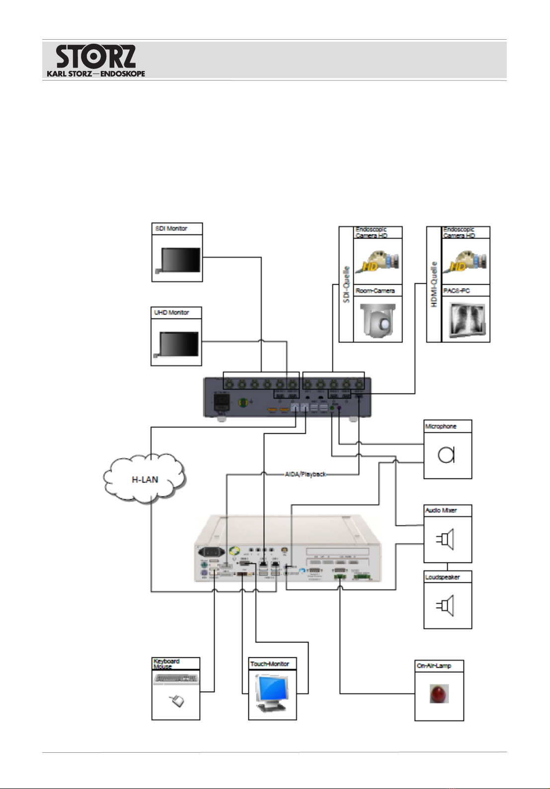
3.3 Possible combinations
It is recommended that the suitability of the products for the intended procedure be checked prior to
use. Please note that the described products in this medium may not be available in all countries due
to different regulatory requirements.
The following diagram shows one option for integrating the OR1.avm and the KARLSTORZ AIDA
system required for control (WD300 and WD350), software version 1.7 or higher, or AIDA C (WD310
and WD360), software version 1.1 or higher.
The system is controlled using a compatible touch screen. Your KARLSTORZ representative can
provide you with additional information.

Product description
Installation instructions • OR1 .avm • PFU293_EN_V3.0_03-2023_II_CE-MDR 12
HIVE router connection diagram
Device HIVE router port
Hospital network uplink HIVE router1
AIDA (WD300)
AIDAC (WD310)
LAN2
HIVE router3
SCB 1.2 (WU300)
LAN1
HIVE router4
OR1.avm (WO301)
LAN2
HIVE router5
Endoscopic Camera (TC201 and TC200) HIVE router6
Lightsource (TL400) HIVE router9
Room Cam (WO10316) HIVE router10
OR1.avm LAN1 cannot be operated via HIVE router port2. OR1.avm LAN1 must be connected
directly to the hospital network.
3.4 Technical specifications
Interfaces
Video inputs 5x 12G SDI
3x HDMI 2.0
Video outputs 6x 12G SDI
2x HDMI 2.0
USB 4x USB 3.0
1x USB 2.0
LAN 2x Ethernet
Audio 1x Audio in
1x Audio out
Remote control 2x ACC
Power supply
Power supply (AC) 100–240V
Operating frequency 50/60Hz
Line fuse 2x T 5A 250V, 5 x 20mm BK/S506-5-R
Max. input current 2.5A (@100VAC), 1A (@ 250VAC)
Operating mode Continuous operation

Product description
Installation instructions • OR1 .avm • PFU293_EN_V3.0_03-2023_II_CE-MDR 13
Housing
Degree of protection acc. to
IEC 60259
IPx0
Electrical protection class I
Dimensions (LxHxW) 355 x 74.5 x 305mm
Weight 4kg
Radiofrequency transmission
Frequency bands in opera-
tion
2.4GHz and 5GHz bands
Operating frequency 2,400–2,485MHz
5,150–5,250MHz
5,250–5,350MHz
5,470–5,725MHz
5,725–5,875MHz
Channel spacing/band width 2.4GHz: 802.11 b/g/n: 5MHz / BT: 1MHz
5GHz: 802.11 a/n/ac: 20, 40, 80, 160MHz
Radiofrequency output en-
ergy
20dBm (2,400–2,485MHz) IEEE 802.11 b/g/n & BT
10dBm (2,400–2,485MHz) BLE
23dBm (5,150–5,725MHz) IEEE 802.11 a/n/ac
13.98dBm (5,725–5,875MHz) IEEE 802.11 a/n/ac
Type of modulation 2.4GHz: DSSS/OFDM/FHSS
5GHz: OFDM
The OR1.avm contains a lithium battery that needs to be checked and replaced regularly.
3.5 Symbols employed
3.5.1 Symbols on the packaging
Symbol Meaning
Manufacturer
Date of manufacture
Medical device
Article no.
Serial number
Number of products in the product packaging
Product description
Installation instructions • OR1 .avm • PFU293_EN_V3.0_03-2023_II_CE-MDR 14
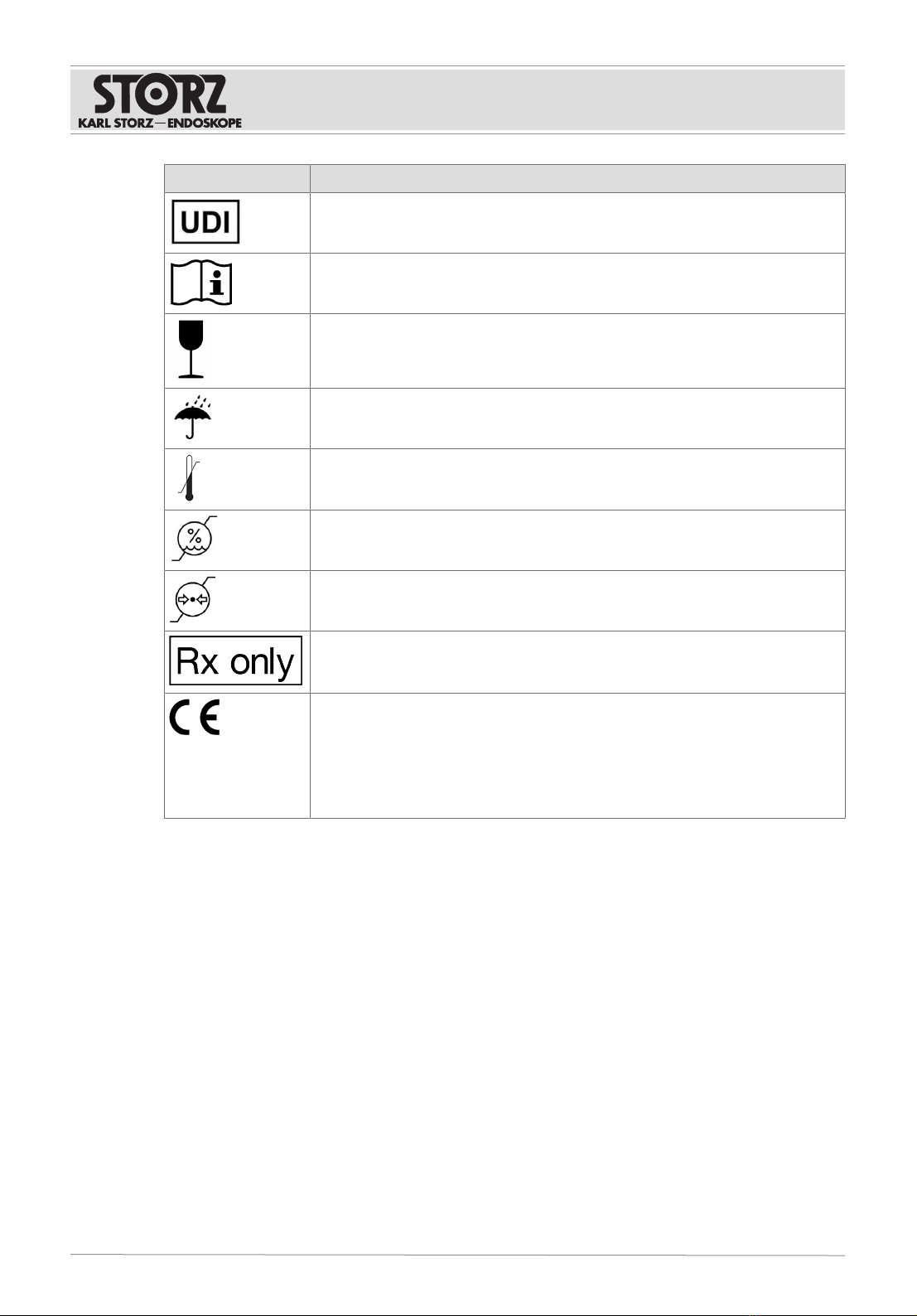
Symbol Meaning
Unique Device Identifier
Consult the printed or electronic instructions for use
Fragile, handle with care
Keep dry
Temperature limit
Humidity limit
Air pressure limit
Federal (USA) law restricts this device to sale by or on the order of a physician.
CE marking
With this marking, the manufacturer declares the conformity of the product
with the applicable EU directives. A code number after the CE mark indicates
the responsible notified body.
The EU directives relevant to the product can be found in the EU Declaration
of Conformity, which can be requested from KARLSTORZ.
Product description
Installation instructions • OR1 .avm • PFU293_EN_V3.0_03-2023_II_CE-MDR 15
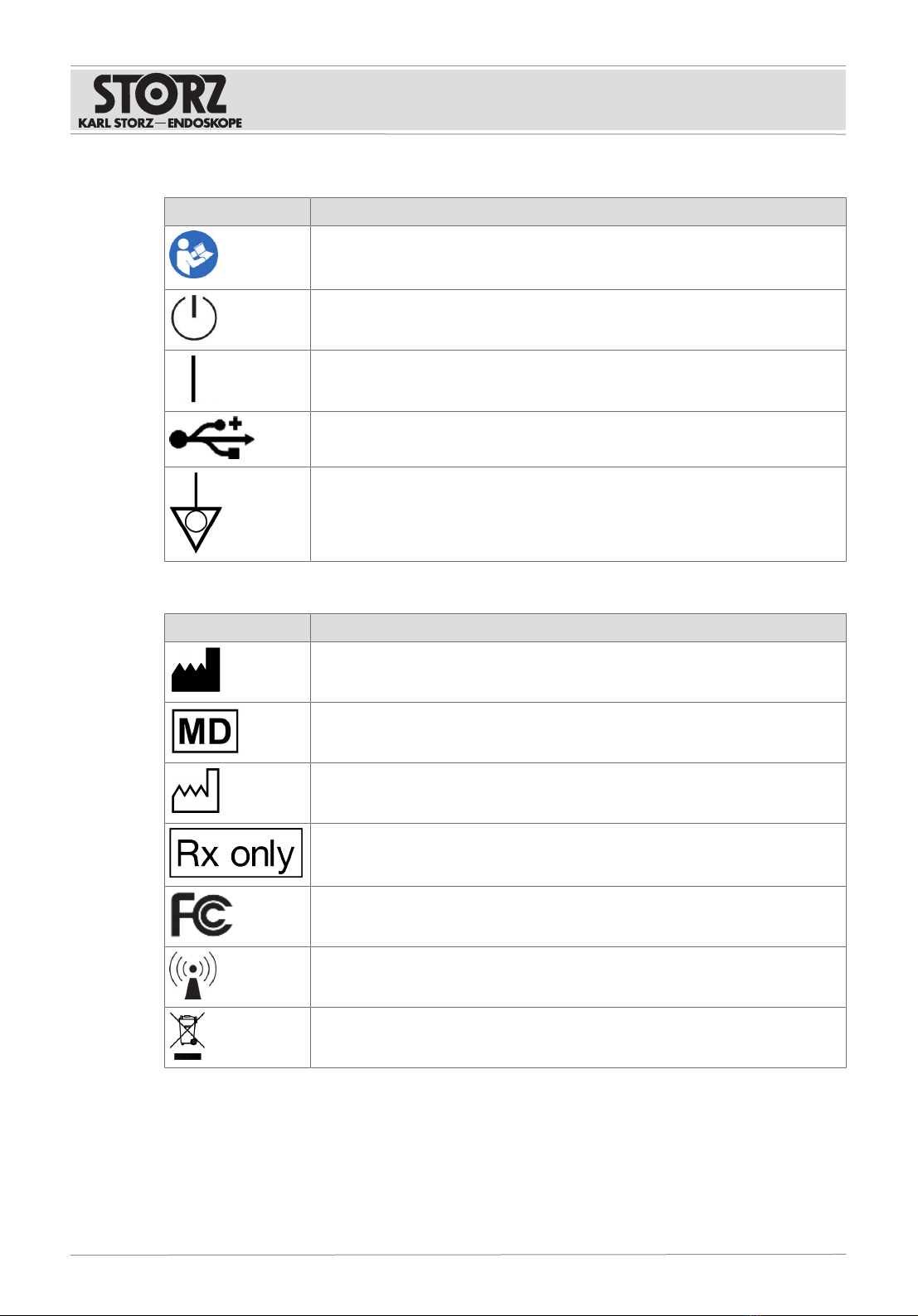
3.5.2 Symbols on the product
Symbol Meaning
Follow the instructions for use.
The color may differ on the product. The symbol is black/white on the packag-
ing label.
Ready/standby button
ON
USB
Potential equalization connector
3.5.3 Symbols on the type plate
Symbol Meaning
Manufacturer
Medical device
Date of manufacture
Federal (USA) law restricts this device to sale by or on the order of a physician.
FCC label
Non-ionizing electromagnetic radiation
Separate collection of electrical and electronic devices.
Do not dispose of in household refuse.
Product description
Installation instructions • OR1 .avm • PFU293_EN_V3.0_03-2023_II_CE-MDR 16
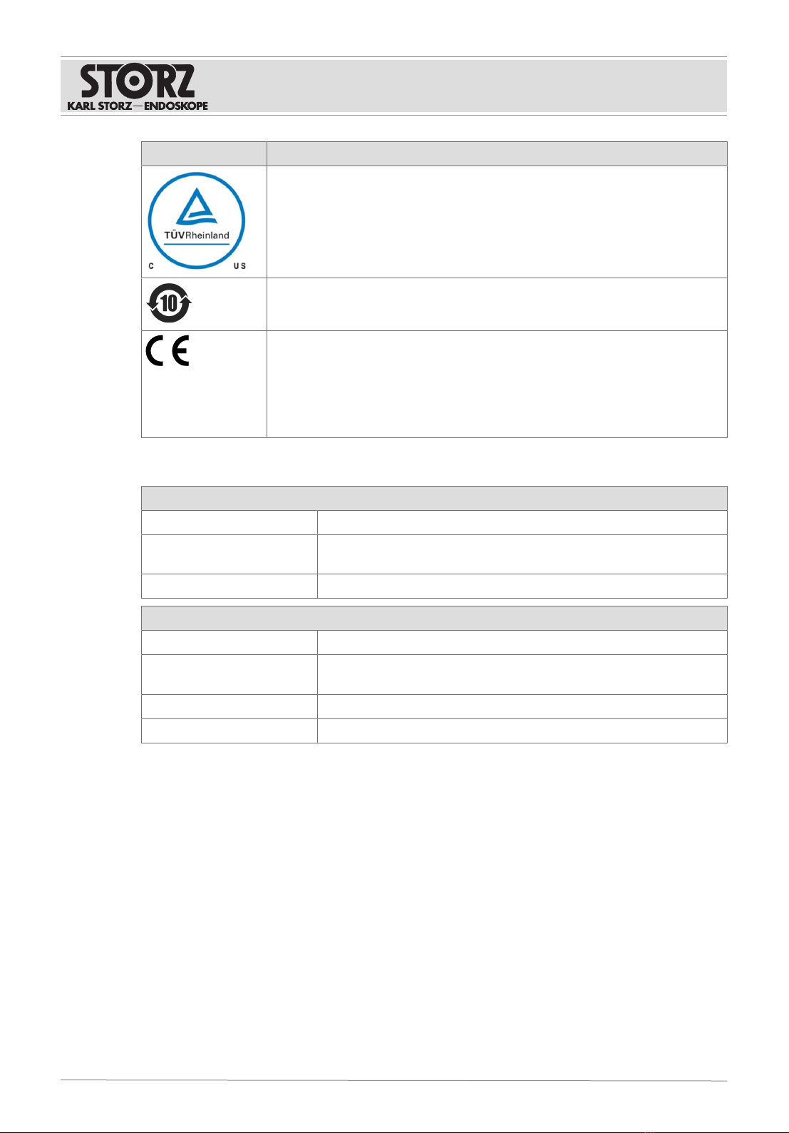
Symbol Meaning
Test mark for electromagnetic compatibility
Environmental protection use period of 10 years (China RoHS)
CE marking
With this marking, the manufacturer declares the conformity of the product
with the applicable EU directives. A code number after the CE mark indicates
the responsible notified body.
The EU directives relevant to the product can be found in the EU Declaration
of Conformity, which can be requested from KARLSTORZ.
3.6 Ambient conditions
Transport and storage conditions
Temperature -10°C...+60°C (14°F...140°F)
Relative humidity
(non-condensing)
10–90%
Air pressure 264–1,080hPa
Operating conditions
Temperature 0°C...40°C (32°F...104°F)
Relative humidity
(non-condensing)
10–90%
Air pressure 700–1,080hPa
Max. operating altitude 3,000m

Preparation
Installation instructions • OR1 .avm • PFU293_EN_V3.0_03-2023_II_CE-MDR 17
4 Preparation
4.1 Unpacking the product
1. Carefully remove the product and accessories from the packaging.
2. Check the delivery for missing items and possible damage.
3. In the case of damage, hidden defects, and short deliveries, document their nature and extent
and contact the manufacturer or supplier immediately.
4. Keep packaging for further transport.
4.2 Setting up the product
WARNING
Blocked air inlets and air outlets! Risk of fire!
If the air inlets and outlets are blocked, the product may overheat. This can cause the product to fail
and start a fire. Users, patients, and third parties may be injured.
Remove any blockages in the air inlets and outlets when setting up the product.
The product can be operated free-standing, in a rack, or as a wall-mounted solution in either a vertical
or horizontal position.
1. Clean and disinfect the product thoroughly before using for the first time.
2. Ensure that the ambient conditions are observed, See section Ambient conditions [p.16].
3. Observe the technical data, Technical specifications.
4. Install the product out of reach of patients.
5. Note the free area dimensions based on the graphic to guarantee that the product is sufficiently
ventilated.
85,9 mm 85,9 mm310 mm
20 mm
375 mm
20 mm
4
1 2 3
5
1 Air outlet 4 Front
2 Housing 5 Defined free areas
3 Air inlet (max. temperature 40°C, 104°F)
Nothing may be mounted in the defined free areas.
4.3 Connecting the product
1. After connecting, a safety check must be performed by authorized, electrically trained
specialists from KARLSTORZSE&Co.KG or an authorized contractual partner.
2. If the product is connected to multiple devices via a portable multiple socket outlet on a cart, the
following measures apply:
Preparation
Installation instructions • OR1 .avm • PFU293_EN_V3.0_03-2023_II_CE-MDR 18
– Note the maximum permitted leakage current of the housing.
– If necessary, use an isolation transformer.
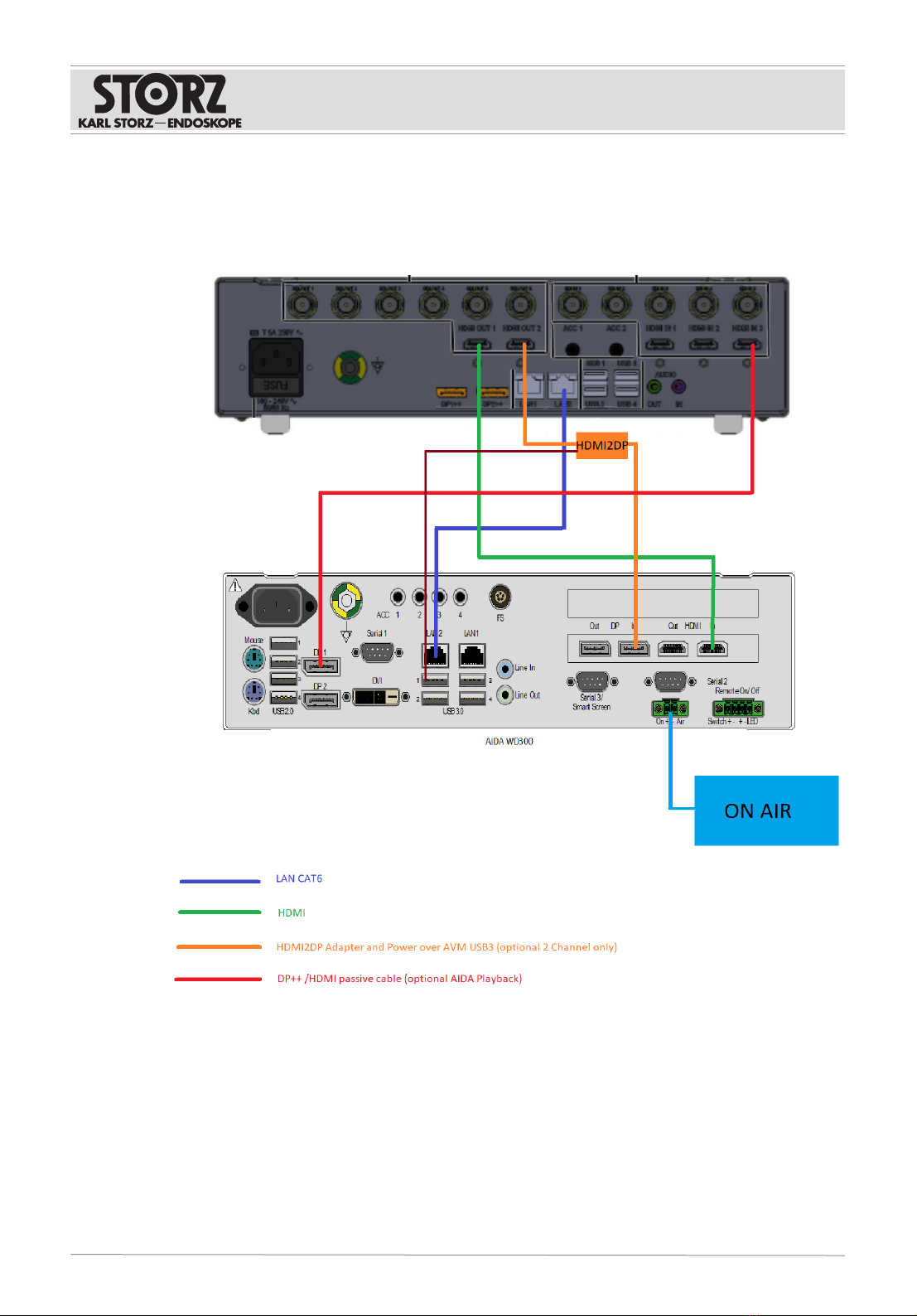
4.3.1 Connecting the OR1 .avm to AIDA
1. Connect the LAN2 port of the OR1 .avm and the LAN2 port of the AIDA with a CAT6 cable.
2. Call up the AIDA configuration area.
3. Click on the Network tab in the General menu.

Preparation
Installation instructions • OR1 .avm • PFU293_EN_V3.0_03-2023_II_CE-MDR 19
4. In the LAN2 drop-down menu, select the Direct connection OR1 .avm status.
5. Connect the AIDA LAN1 port to the hospital network.
6. If the Streaming function is to be used, connect the OR1.avm LAN1 to the hospital network.
4.3.2 Connecting the audio cabling
The following diagram shows how to connect the audio devices to OR1.avm:

Preparation
Installation instructions • OR1 .avm • PFU293_EN_V3.0_03-2023_II_CE-MDR 20
4.3.3 Connecting the HIVE router
The HIVE router must be used if at least one of the following conditions is met:
– IMAGE1 S is communicating with AIDA.
– More than two HIVE devices are connected.
– A room camera is being controlled.
– SCB 1.2 (WU300) is connected.
1. Connect the HIVE router LAN1 port to the hospital network.
2. Call up the AIDA configuration area.
3. Click on the Network tab in the General menu.
4. Open the LAN2 drop-down menu and select HIVE Router.
Table of contents
Other Storz Analytical Instrument manuals

Storz
Storz OR1 FUSION WO300 User manual

Storz
Storz 11272 VA User manual

Storz
Storz 11301 BNX Series User manual

Storz
Storz 11272 VN User manual

Storz
Storz C-MAC S User manual

Storz
Storz VIDEOSCOPE User manual

Storz
Storz C-MAC 8401 Series User manual

Storz
Storz 11302 BDX User manual

Storz
Storz 112 Series User manual


