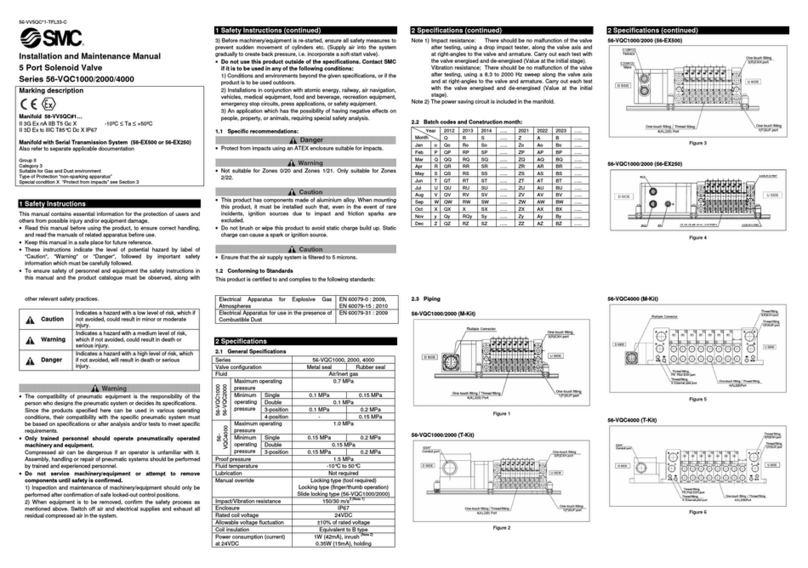
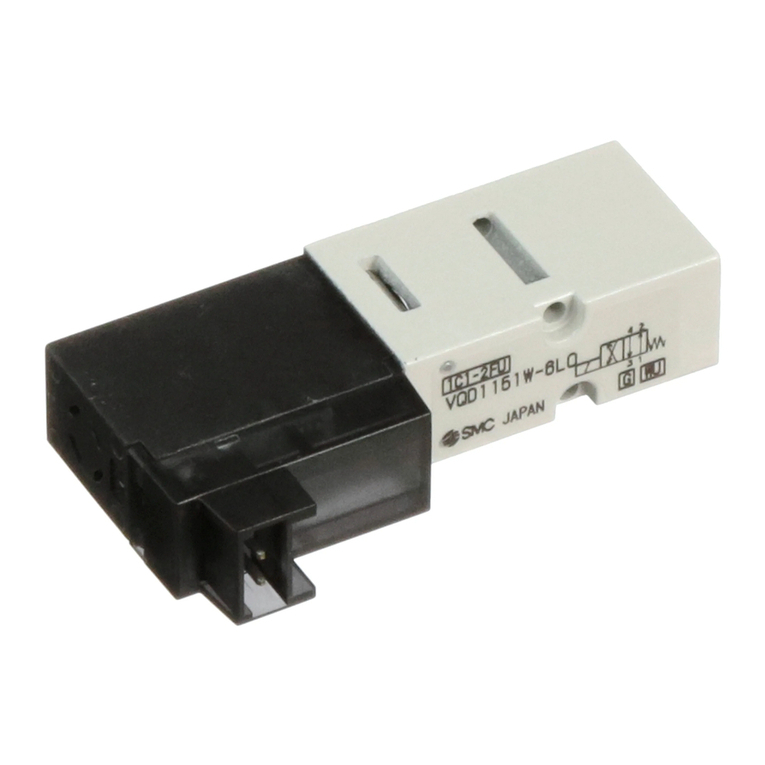
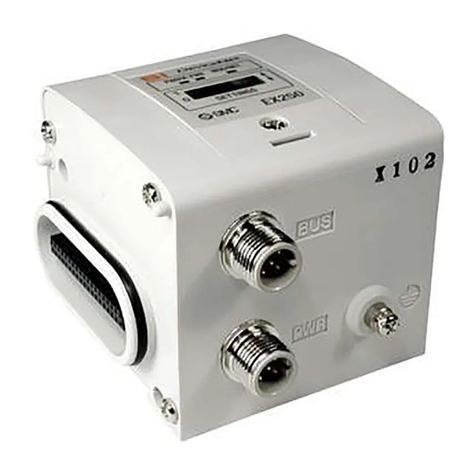
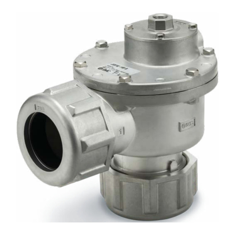
manuals.online logo
Brands
  1. Home
  2. •
  3. Brands
  4. •
  5. SMC Networks
  6. •
  7. Control Unit
  8. •
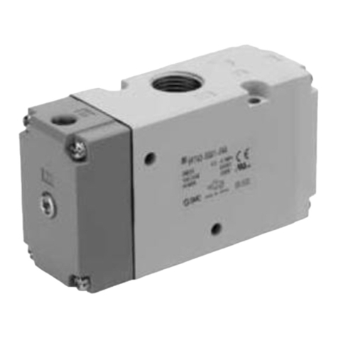
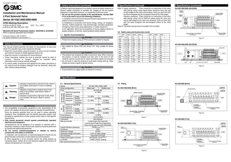
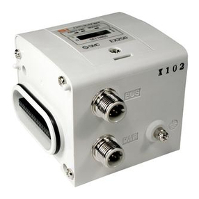
  9. SMC Networks JSY1000 Series User manual

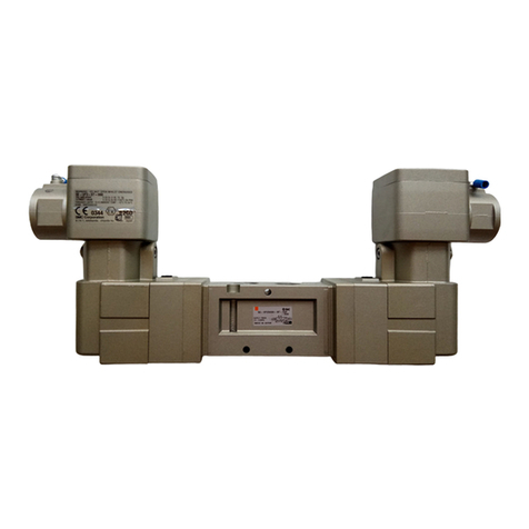
SMC Networks JSY1000 Series User manual

A, B port size: Ø 2, Ø 4, Ø 6 A, B port size: Ø 6, Ø 8 A, B port size: Ø 10, Ø 12
6.4 mm 10 mm 15 mm
Ø 25
Ø 40
Ø 63
100 300 500
310
550
140
Ø 40
Ø 50
Ø 100
100 300 500
430
520
110
100 300 500
Ø 63
Ø 80
Ø 160
540
360
100
New
New
New
Bore size [mm]
Bore size [mm]
Bore size [mm]
Cylinder speed [mm/s] Cylinder speed [mm/s] Cylinder speed [mm/s]
Ø 6 One-touch fitting
Ø 8 One-touch fitting
Ø 12 One-touch fitting
Refer to pages 9 to 12 for detailed conditions regarding the above cylinder speeds.
Size reduction has been made possible thanks to a flow increase.
This allows for space saving , weight reduction , and a large flow rate .
Can drive Ø 40∗1bore cylinders
Can drive Ø 50∗1bore cylinders Can drive Ø 80∗1bore cylinders
JSY1000 JSY3000 JSY5000
JSY1000
JSY3000
JSY5000
∗1 The cylinder speed is 300 mm/s.
Can be connected with the ZK2 series
vacuum unit p. 7
JSY3000
Vacuum Unit ZK2
Ejector System
JSY1000/3000/5000 Series
CAT.EUS11-110B-UK
Compact 5-Port Solenoid Valve
Plug-in
2
D-sub Connector
IP67
FW type
IP40
Connector entry direction
adjustable F type
IP20
Compact type: FC type
JSY1000
JSY3000
JSY5000
Compatible protocol
Series
Serial Transmission
DeviceNet™ PROFIBUS DP CC-Link
EtherNet/IP™
EtherCAT®PROFINET
Integrated
type
(For input/
output)
EX600
EX245
EX250
Integrated
type
(For output)
EX260
EX120
n
e
p. 21 p. 21
LateralUpward
p. 21
∗1∗1
∗2
∗1 Compatible with wireless systems ∗2 JSY3000/5000
29 %
reduction
39 %
reduction
36 %
reduction
35 %
reduction
Wiring
Plug-in Compact 5-Port Solenoid Valve JSY1000/3000/5000 Series
1597
691
263
106.4 15.5 24.6
JSY1000 JSY3000 JSY5000
Q [l/min (ANR)]
760 a1597
Q [l/min (ANR)]
247 a691
2.8
times
2.1
times
Series Map
460 gb
650
g
3
r
770
gb
1140
g
3
r
Weight
Valve
width
3
r
1500
gb
3700
g
6.4
mm b
10
mm
10
mm b
15.5
mm
15 mm b24.6 mm
JSY1000 Series VQ1000
VQ2000
Lightweight: 29 % lighter
460 g b650 g
Lightweight: 32 % lighter
770 g b1140 g
SY1000
59 %
reduction
JSY3000 Series
32 %
reduction
Flow rate
Q [l/min (ANR)]
Valve width [mm]
JSY5000 Series
Lightweight: 59 % lighter
1500 g b3700 g
VQ4000
JSY5000
0
00
3
Flat Ribbon Cable Terminal Block Box
Lead Wire
Connector entry
direction adjustable
P/PG/PH type
Compact type
PC/PGC/PHC type
Spring type
TC type
T type
Serial Transmission
CANopen
AS-Interface
OMRON
CompoBus/S
CompoNet™
EtherNet/IP™
compatible wireless base
PROFINET
compatible wireless base
IO-Link PROFIsafe
Ethernet
POWERLINK
pe
e
re
Lateral
Upward
p. 21 p. 21 p. 43 p. 43 p. 55
Connector type manifold
Power consumption
A 4-position dual 3-port valve is available.
¡Features two 3-port valves built into one body
Plug-in Compact 5-Port Solenoid Valve JSY1000/3000/5000 Series
Plug-in
Series A side B side
JSYA0N.C. valve N.C. valve
JSYB0N.O. valve N.O. valve
JSYC0N.C. valve N.O. valve
¡
The 3-port valves on the A and B sides can be operated independently.
¡
When used as a 3-port valve, only half the number of stations are required.
¡Can also be used as a 4-position, 5-port valve
¡Combination examples
0.2
W
0.1
W
∗1 Made to Order
0.4
W
∗2 The JSY1000 series is only available
as the power-saving type.
∗2
∗1JSY1000JSY3000/5000 JSY3000/5000
With power-
saving circuit Standard
<Enlarged view of
the connector>
Connector type manifold 32 outputs
A side
spool valve B side
spool valve
4
Application Examples
The EX600-W series is compatible with wireless systems.
The EX260 series supports safety communication (PROFIsafe).
For tool changing
Noise resistance

This is a Fieldbus unit which supports safety standard ISO 13849-compliant safety circuit constructions.
Using the safety communication protocol

Communication cables not required
High-speed connection
Number of I/O points
Communication response
Compatible protocols
For spot welding
For rotary tables
In welding environments
Power supply
line only
Power supply
line
Communication
line
¡Uses the 2.4 GHz ISM frequency band
¡Frequency hopping: Every 5 ms
Refer to the EX260 Web Catalogueue for details on units that support the safety communication protocol.
When using a manifold valve within an ISO 13849-compliant safety system, the device needs to be considered
from both the pneumatic circuit and the electric side.
Devices (including valves) need to be selected based on whether their functions are in line with the safety level
of the equipment as a whole.
The use of valves that have been validated as being compliant with ISO 13849-2 may be required.
For details on valves that have been validated, please contact SMC.
In addition, refer to “Safety Instructions” for precautions on model selection.
¡Reduced wiring work, space, and cost
¡Minimised disconnection risk
¡
From power supply ON to start of communication:
Min. 250 ms∗1
∗1 For the wireless remote type
¡Max. 1280 inputs/1280 outputs
(Max. 128 inputs/128 outputs per module)
¡Wireless communication signal
Response time: 5 ms
Wired system
PROFIsafe is established as an international standard (IEC 61784-3-3). It is a communication
protocol that transmits safety-related data by PROFINET communication and can be used up
until safety standards ISO 13849-1 PL e and IEC 61508/IEC 62061 SIL 3.
Plug-in Compact 5-Port Solenoid Valve JSY1000/3000/5000 Series
p. 63
5
5
5
Application Examples
Plug-in Compact 5-Port Solenoid Valve JSY1000/3000/5000 Series
JSY5000
JSY3000
JSY1000
5
6
 Standard  Option Made to Order
Blanking plate
Used when valve additions are expected or for maintenance
Individual SUP spacer
When the same manifold is to be used for different pressures,
an individual SUP spacer can be used to act as a supply port
for different pressures.
Individual EXH spacer
When valve exhaust affects other stations due to the circuit
configuration, this spacer can be used for individual valve
exhaust.
(A)
4
(B)
2
5
(
EA
)
1
(
P
)
3
(
EB
)
Circuit diagram
Circuit diagram
(Mounting example of a
2-position single valve)
2-position single valve
1(P')
2(B)
4(A)
3
(
EB
)
1(P)
5(EA)
Individual SUP
spacer assembly
Circuit diagram
(Mounting example of a
2-position single valve)
2-position single valve
3/5(E')
2(B)
4(A)
3
(
EB
)
1(P)
5(EA)
Individual EXH
spacer assembly
p. 132p. 132
p. 132
Flow rate
Q [l/min (ANR)]
4/2J5/3
(A/BJEA/EB) Type of actuation Rated
voltage
Port size
4(A), 2(B) port
1(P),
3/5(E)
port
Ø 2 Ø 4 Ø 6 Ø 8 Ø 10 Ø 12
4(A), 2(B)
port
JSY1000
Ø 4 250
24
VDC

Ø 8
Ø 6 263 
JSY3000
Ø 8 691  Ø 10
JSY5000
Ø 12 1597 Ø 12
Plug-in Compact 5-Port Solenoid Valve JSY1000/3000/5000 Series
Series Variations
2-position single
(A)4 2(B)
1
(
P
)
3(EB)(EA)5
2-position double
(A)4 2(B)
1
(
P
)
3(EB)(EA)5
3-position closed centre
(EA)5 1
(
P
)
3(EB)
(A)4 2(B)
3-position exhaust centre
(EA)5 1
(
P
)
3(EB)
(A)4 2(B)
3-position pressure centre
(EA)5 1
(
P
)
3(EB)
(A)4 2(B)
4-position dual 3-port valve
N.C. valve x 2 pcs.
5
(
EA
)
3
(
EB
)
1
(
P
)
4(A) 2(B)
N.O. valve x 2 pcs.
3
(
EB
)
5
(
EA
)
1
(
P
)
2(B)4(A)
N.C. valve, N.O. valve x 1 pc. of each
3
(
EB
)
5
(
EA
)
1
(
P
)
2(B)4(A)
Silencer (One-touch fitting connection type)
This silencer can be mounted to the 3/5 (E: EXH) port of the
manifold in one step.
p. 133
Manifold Options
Ø
2-position single valve
Individual SUP
spacer assembly
Individual EXH
spacer assembly
2-position single valve
7
∗1 Refer to “Manifold Specifications” on pages 17 and 18 for details on IP67.
Manifold Options
Tube Releasing Tool
This tool can be used to remove tubes from
ports A and B.
SUP/EXH blocking disk
(For the connector type manifold,Type 10)
[SUP blocking disk]
Inserting an SUP blocking disk in the pressure supply passage
of a manifold valve can allow for the use of 2 different pressures
(high and low) in 1 manifold.
[EXH blocking disk]
Inserting an EXH blocking disk in the exhaust passage of a
manifold valve can separate the exhaust from the valve so it
does not affect the other valves. It can also be used in positive
pressure and vacuum pressure mixed manifolds. (2 pieces are
required to block both the EA and EB sides of the EXH.)
SUP/EXH
blocking disk
label
EXH
blocking disk
label
SUP
blocking disk
label
A4
B2
A4
B2
A4
B2
A4
B2
A4
B2
DDD
3/5
E
1P
3/5
E
P1
2B
p. 130
p. 133
7
Pitch
width
[mm]
Wiring Manifold options Valve options
Common specifications
Blanking plate
Individual SUP
spacer
Individual EXH
spacer
SUP/EXH
blocking disk
Label for
blocking disk
Silencer (One-touch
fitting connection type)
Built-in silencer
Vacuum/Low-
pressure
specification
Different
pressures
Reverse
pressure
Mixed fitting
sizes
Enclosure
IP67∗1
Positive
common
Negative
common
6.5
 
p. 132

p. 132

p. 132

p. 133

p. 133

p. 133

External
pilot

Individual
SUP

External
pilot

—
9
11.5 
16 
Plug-in Compact 5-Port Solenoid Valve JSY1000/3000/5000 Series
For JSY1000 For JSY3000 For JSY5000
Ø 8 Ø 12
Ø 6
Labels for blocking disks
These labels can be used to indicate and confirm where on the
manifold the SUP/EXH blocking disk assemblies were inserted.
(3 labels of each)
p. 133
Ø 10
Ø 4
Ø 2
SUP/EXH
blocking
disk label
SUP
blocking
disk label
EXH
blocking
disk label
8
Plug-in Compact 5-Port Solenoid Valve JSY1000/3000/5000 Series
JSY3000 valves and ZK2 ejectors can be connected to the same manifold.
This allows for a compact body and
reduced wiring/wiring labour
.
Vacuum Unit ZK2 Combination Manifold
Valve Manifold
JSY3000 Series
Ejector Manifold
ZK2 Series
Centralised electrical wiring for
ejectors and valves (Reduced
wiring)
Wiring and piping for valves and ejectors can be arranged
in the same direction. (Wiring method: Terminal block box
and lead wire or EX250 and EX260)
The individual pressure supply to the valve
manifold (JSY3000) and ejector manifold (ZK2)
prevents the reduction of vacuum pressure
due to pressure interference.
Max. number of outputs: 32 (Valve + Ejector)
Valve stations: 2 to 24 stations (Max. number of outputs: 30,
Depends on whether single or double)
Ejector stations: 1 to 8 stations (Max. number of outputs: 16)
The centralised electrical wiring can be connected to the fieldbus system.
Integrated manifold
Centralised wiring and piping directionsSpecifications
Various selectable wiring methods
Fieldbus compatible
DeviceNet™, PROFIBUS DP, CC-Link, EtherNet/IP™, EtherCAT, PROFINET,
EtherNet/IP™ compatible wireless base, PROFINET compatible wireless base
DeviceNet™, PROFIBUS DP, CC-Link, EtherNet/IP™, EtherCAT
PROFINET, Ethernet POWERLINK, IO-Link, PROFIsafe
PROFINET
DeviceNet™, CC-Link, OMRON CompoBus/S, CompoNet™
EX245
EX120
EX600
EX260
EX250 DeviceNet™, PROFIBUS DP, EtherNet/IP™
CANopen, AS-Interface
¡For Input/Output
D-sub connector
Terminal block box
¡
Compact type: FC type (IP20)
¡Connector entry direction
adjustable: F type (IP40)
¡FW type (IP67)
¡Spring type: TC type
¡T type
Flat ribbon cable
Lead wire
¡Compact type: PC/PGC/PHC type
¡Connector entry direction
adjustable: P/PG/PH type
Individual pressure supply
¡For Output
p. 119
JSY3000
supply/exhaust
ZK2 supply/exhaust
Connecting part
Electrical wiring
9
CONTENTS
D-sub Connector, Flat Ribbon Cable [IP20/40/67]
How to Order ··············································································· p. 21
Dimensions
D-sub Connector (IP40/Connector Entry Direction Adjustable): F
······ p. 23
D-sub Connector (IP67): FW ···················································· p. 27
D-sub Connector (IP20/Compact Type): FC ····························· p. 29
Flat Ribbon Cable
(IP40/Connector Entry Direction Adjustable): P/PG/PH ······· p. 32
Flat Ribbon Cable (IP20/Compact Type): PC/PGC/PHC ········· p. 36
Electrical Wiring Specifications: D-sub Connector Cable ············ p. 39
Electrical Wiring Specifications: Flat Ribbon Cable Connector
······ p. 40
Spring Type Terminal Block Box, Terminal Block Box
How to Order ··············································································· p. 43
Dimensions
Spring Type Terminal Block Box: TC ········································ p. 45
Terminal Block Box: T······························································ p. 49
Connection/Electrical Wiring Specifications ································ p. 53
Lead Wire
How to Order ··············································································· p. 55
Dimensions ·················································································· p. 57
Electrical Wiring Specifications ···················································· p. 61
EX600 Integrated Type (For Input/Output)
Serial Transmission System
How to Order ··············································································· p. 63
Dimensions ·················································································· p. 65
EX245 Integrated Type (For Input/Output)
Serial Transmission System
How to Order ··············································································· p. 73
Dimensions ·················································································· p. 75
EX250 Integrated Type (For Input/Output)
Serial Transmission System
How to Order ··············································································· p. 77
Dimensions ·················································································· p. 79
EX260 Integrated Type (For Output)
Serial Transmission System
How to Order ··············································································· p. 83
Dimensions ·················································································· p. 87
EX120 Integrated Type (For Output)
Serial Transmission System
How to Order ··············································································· p. 91
Dimensions ·················································································· p. 93
Type 10/Side Ported: Common Dimensions
(External Pilot, Built-in Silencer/Mixed Size, Straight Port Type)
······ p. 97
Manifold Exploded View [By Wiring] ························· p. 101
D-sub Connector/Flat Ribbon Cable
(IP40/Connector Entry Direction Adjustable) ························· p. 102
D-sub Connector (IP67) ························································· p. 103
D-sub Connector/Flat Ribbon Cable (IP20/Compact Type)
······ p. 104
Spring Type Terminal Block Box ············································· p. 105
Terminal Block Box ································································ p. 106
Lead Wire ··············································································· p. 107
EX600 ···················································································· p. 108
EX245 ···················································································· p. 110
EX250 ···················································································· p. 112
EX260 ···················································································· p. 113
EX120 ···················································································· p. 114
Manifold Exploded View [Common Parts] ··············· p. 115
Type 10: How to Increase Connector Type Manifolds ············ p. 115
For the JJ5SY1-10, JJ5SY3-10, JJ5SY5-10/
Manifold Parts Nos. ···························································· p. 116
Vacuum Unit ZK2 Combination Manifold
How to Order ············································································· p. 119
Dimensions ················································································ p. 123
ZK2 Combination Manifold Exploded View ············· p. 126
For the JJ5SY3-10-M (ZZK2A) ··········································· p. 126
Manifold Parts Nos. ································································ p. 127
ZK2A Vacuum Ejector Manifold Exploded View
How to Increase Manifold Stations ········································· p. 128
One-touch Fittings, Plug, Clip, Port Plate,
Tube Releasing Tool ······················································· p. 130
Manifold Options ·································································· p. 131
Made to Order ····································································· p. 135
Specific Product Precautions ············································ p. 136
Model Index ··········································································· p. 141
Safety Instructions ······················································ Back cover
D-sub connector
Flat ribbon cable Lead wire
EX600 EX250
EX245
EX120
Terminal block box
EX260
Optimum Actuation Size Chart of Air Cylinder ······························· p. 9
Valve Specifications ···································································· p. 13
Response Time ··········································································· p. 14
Valve Weight ··············································································· p. 14
Valve Construction ······································································ p. 15
Valve Replacement Parts: Pilot Valve ········································· p. 16
Plug-in Connector Connecting Base
Manifold Specifications ································································ p. 17
Manifold Weight ··········································································· p. 17
Manifold Flow Rate Characteristics ············································· p. 17
ZK2 Combination Manifold Weight ·············································· p. 18
Connector Wiring Layout ····························································· p. 19
20
ZK2 combination manifold
10
CJ2 series
Pressure: 0.5 MPa
Load ratio: 50 %
Stroke: 60 mm
Ø 6
Ø 10
Ø 16
CM2 series
Pressure: 0.5 MPa
Load ratio: 50 %
Stroke: 300 mm
Ø 20
Ø 25
Ø 32
Ø 40
CA2 series
Pressure: 0.5 MPa
Load ratio: 50 %
Stroke: 500 mm
Ø 50
Ø 63
Ø 80
Average speed [mm/s]
0 100 200 300 400 500 600 700 800
0 100 200 300 400 500 600 700 800
Optimum Actuation Size Chart of Air Cylinder
∗Values at extension of a directly coupled cylinder when meter-out speed controllers are used with the needle full open.
∗The average speed of the cylinder is obtained by dividing the stroke by the total stroke time.
∗Formula for load ratio: Load ratio = ((Load mass x 9.8)/Theoretical output) x 100 %
∗Cylinder for horizontal use are based on the coefficient of rolling friction 0.1.
∗Operating piston speed is different depending on the applicable cylinder. Refer to the cylinder catalogueue for details.
For JSY1000, A, B port: Ø 4
Horizontal Vertical (Upward)
r
11
CJ2 series
Pressure: 0.5 MPa
Load ratio: 50 %
Stroke: 60 mm
Ø 6
Ø 10
Ø 16
CM2 series
Pressure: 0.5 MPa
Load ratio: 50 %
Stroke: 300 mm
Ø 20
Ø 25
Ø 32
Ø 40
CA2 series
Pressure: 0.5 MPa
Load ratio: 50 %
Stroke: 500 mm
Ø 50
Ø 63
Ø 80
Ø 100
Average speed [mm/s]
0 100 200 300 400 500 600 700 800
0 100 200 300 400 500 600 700 800
For JSY1000, A, B port: Ø 6
Horizontal Vertical (Upward)
Optimum Actuation Size Chart of Air Cylinder
∗Values at extension of a directly coupled cylinder when meter-out speed controllers are used with the needle full open.
∗The average speed of the cylinder is obtained by dividing the stroke by the total stroke time.
∗Formula for load ratio: Load ratio = ((Load mass x 9.8)/Theoretical output) x 100 %
∗Cylinder for horizontal use are based on the coefficient of rolling friction 0.1.
∗Operating piston speed is different depending on the applicable cylinder. Refer to the cylinder catalogueue for details.
r
12
CM2 series
Pressure: 0.5 MPa
Load ratio: 50 %
Stroke: 300 mm
Ø 32
Ø 40
CA2 series
Pressure: 0.5 MPa
Load ratio: 50 %
Stroke: 500 mm
Ø 50
Ø 63
Ø 80
Ø 100
CS1 series
Pressure: 0.5 MPa
Load ratio: 50 %
Stroke: 1000 mm
Ø 125
Ø 140
Average speed [mm/s]
0 100 200 300 400 500 600 700 800
0 100 200 300 400 500 600 700 800
For JSY3000, A, B port: Ø 8
Horizontal Vertical (Upward)
Optimum Actuation Size Chart of Air Cylinder
∗Values at extension of a directly coupled cylinder when meter-out speed controllers are used with the needle full open.
∗The average speed of the cylinder is obtained by dividing the stroke by the total stroke time.
∗Formula for load ratio: Load ratio = ((Load mass x 9.8)/Theoretical output) x 100 %
∗Cylinder for horizontal use are based on the coefficient of rolling friction 0.1.
∗Operating piston speed is different depending on the applicable cylinder. Refer to the cylinder catalogueue for details.
er
13
Average speed [mm/s]
CA2 series
Pressure: 0.5 MPa
Load ratio: 50 %
Stroke: 500 mm
Ø 50
Ø 63
Ø 80
Ø 100
CS1 series
Pressure: 0.5 MPa
Load ratio: 50 %
Stroke: 1000 mm
Ø 125
Ø 140
Ø 160
Ø 180
Ø 200
0 100 200 300 400 500 600 700 800 900 1000
0 100 200 300 400 500 600 700 800 900 1000
For JSY5000, A, B port: Ø 12
Horizontal Vertical (Upward)
Optimum Actuation Size Chart of Air Cylinder
∗Values at extension of a directly coupled cylinder when meter-out speed controllers are used with the needle full open.
∗The average speed of the cylinder is obtained by dividing the stroke by the total stroke time.
∗Formula for load ratio: Load ratio = ((Load mass x 9.8)/Theoretical output) x 100 %
∗Cylinder for horizontal use are based on the coefficient of rolling friction 0.1.
∗Operating piston speed is different depending on the applicable cylinder. Refer to the cylinder catalogueue for details.
r
14
Valve Specifications
∗1 Not available for the JSY1000 series
∗2 Impact resistance: No malfunction occurred when tested in the axial direction and at a right angle to the main valve and armature in both an energised
and a de-energised state, once in each condition. (Value in the initial state)
Vibration resistance: No malfunction occurred in a one-sweep test between 45 and 2000 Hz in the axial direction and at a right angle to the main valve
and armature in both an energised and a de-energised state, once in each condition. (Value in the initial state)
Refer to page 139 for details on securing the DIN rail mounting type manifold.
∗3 The JSY1000 series is only available as the power-saving type. Standard type (without power-saving circuit) cannot be selected.
∗4 For details, refer to page 137.
JSY1000/3000/5000 Series
Valve Specifications
Valve type Rubber seal
Fluid Air
Internal pilot operating
pressure range
[MPa]
2-position single 0.15 to 0.7
2-position double 0.1 to 0.7
3-position 0.2 to 0.7
4-position dual 3-port valve 0.15 to 0.7
External pilot
(Made to Order)
operating pressure range
[MPa]
Operating pressure range –100 kPa to 0.7
Pilot
pressure
range
2-position single
0.25 to 0.72-position double
3-position
Ambient and fluid temperatures [°C] −10 to 50 (No freezing)
Max. operating frequency
[Hz]
JSY1000/3000
2-position single/double
5
4-position dual 3-port valve
3-position 3
JSY5000
2-position single/double
5
4-position dual 3-port valve
3
3-position 3
Manual override
Non-locking push type
Push-turn locking slotted type
Push-turn locking lever type∗1
Pilot exhaust type Internal pilot Individual exhaust
External pilot (Made to Order)
Lubrication Not required
Mounting orientation∗2Unrestricted
Impact/Vibration resistance∗2[m/s2]150/30
Enclosure JSY1000: IP40
JSY3000/5000: IP67 (Based on IEC 60529)
Coil rated voltage [DC] 24 V
Allowable voltage fluctuation [V] ±10 % of the rated voltage
Power consumption [W]
Standard JSY3000/5000 0.4
With power-
saving circuit
JSY1000 0.2∗3[Inrush 0.5, Holding 0.2]
JSY3000/5000
(Made to Order) 0.1∗4[Inrush 0.4, Holding 0.1]
Surge voltage suppressor Diode (Varistor for non-polar type)
Indicator light LED
15
Response Time
∗1 Based on dynamic performance test, JIS B 8419-2010 (Coil temperature: 20 °C, at rated voltage)
Series Model Type of actuation
Response time [ms]∗1
With light/surge voltage suppressor
Z type U type
JSY1000
JSY1100 2-position single 15
—
JSY1200 2-position double 7
JSY13/4/500 3-position 16
JSY1A/B/C00 4-position dual 3-port valve 19
JSY3000
JSY3100 2-position single 27 18
JSY3200 2-position double 13 12
JSY33/4/500 3-position 27 24
JSY3A/B/C00 4-position dual 3-port valve 23 23
JSY5000
JSY5100 2-position single 35 25
JSY5200 2-position double 19 17
JSY53/4/500 3-position 41 37
JSY5A/B/C00 4-position dual 3-port valve 37 37
JSY1000 Series
Valve Weight
JSY3000 Series
Valve model Type of actuation Weight [g]
JSY300
2-position Single 54
Double 63
3-position
Closed centre
67Exhaust centre
Pressure centre
4-position Dual 3-port valve 63
Valve model Type of actuation Weight [g]
JSY100
2-position Single 24
Double 27
3-position
Closed centre
30Exhaust centre
Pressure centre
4-position Dual 3-port valve 27
JSY5000 Series
Valve model Type of actuation Weight [g]
JSY500
2-position Single 91
Double 100
3-position
Closed centre
110Exhaust centre
Pressure centre
4-position Dual 3-port valve 96
Valve Specifications JSY1000/3000/5000 Series
16
5
(EA)
4
(A)
3
(EB)
2
(B)
1
(P)
qerw qerw
qerw qerw
Rubber Seal
2-position single
JSY1000/3000/5000 Series
Valve Construction
2-position double
4-position dual 3-port valve
3-position closed centre/exhaust centre/pressure centre
2-position single
(A)4 2(B)
1
(
P
)
3(EB)(EA)5
3-position closed centre
(EA)5 1
(
P
)
3(EB)
(A)4 2(B)
3-position pressure centre
(EA)5 1
(
P
)
3(EB)
(A)4 2(B)
3-position exhaust centre
(EA)5 1
(
P
)
3(EB)
(A)4 2(B)
4-position dual 3-port valve
N.C. valve x 2 pcs.
5
(
EA
)
3
(
EB
)
1
(
P
)
4(A) 2(B)
N.O. valve x 2 pcs.
3
(
EB
)
5
(
EA
)
1
(
P
)
2(B)4(A)
N.C. valve, N.O. valve x 1 pc. of each
3(EB)5(EA) 1(P)
2(B)4(A)
2-position double
(A)4 2(B)
1
(
P
)
3(EB)(EA)5
Component Parts
No. Description Material
1 Body Aluminium die-casted
2 Spool valve
Aluminium/HNBR
4-position solenoid valve:
Resin/HNBR
3 Piston Resin
4
Pilot valve assembly
—
17
w
w
q
∗2
Pilot valve mounting screw (M2 x 25)
Ti
g
htenin
g
tor
q
ue: 0.15 N·m
∗2
Pilot valve mounting screw (M2 x 16.5)
Tightening torque: 0.15 N·m
b-side pilot valve
∗1
Socket
∗1
Gasket
a-side pilot valve
Pilot cover
B tight flat head screw (M1.7)
Tightening torque: 0.12 N·m
Pilot valve assembl
y
How to Order Pilot Valves (With a gasket and two mounting screws)∗3
V112
Rated voltage
Coil type
¡Loosen B tight flat head screw to remove the pilot cover in the direction
indicated by the arrow q.
¡Remove the pilot valve mounting screws.
¡Remove the pilot valve in the direction indicated by the arrow w.
∗Assemble by following the removal procedure in reverse.
∗1 Ensure the gasket is mounted, and take care not to bend the socket.
∗2 Be noted for mounting that there are two types of lengths for the pilot valve mounting
screws.
∗3 The pilot valve of the JSY1000 cannot be removed. This is irreplaceable.
How to replace pilot valves
1. The coil specification and voltage (including light/
surge voltage suppressor) cannot be changed by
changing the pilot valve assembly.
2. When selecting the standard coil type, it is not
possible to change to the power-saving circuit type.
3. Replacement pilot valve for the JSY3000/5000
Caution
Pilot cover
∗Pilot cover x 1 + B tight flat
head screw x 1
Series Part no.
JSY3000 SY30V-25AS
JSY5000 SY50V-25A
—Standard
T
With power-saving circuit
(Made to Order)
524 VDC
JSY3000/5000 Series
Valve Replacement Parts: Pilot Valve
A
5
∗2
B tight flat head screw (M1.7)
Tightening torque: 0.12 N·m
Pilot cover
Gasket
Socket
a-side pilot valve
Pilot valve assembly
b-side pilot valve
Pilot valve mounting screw (M2 x 16.5)
Tightening torque: 0.15 N·m
Pilot valve mounting screw (M2 x 25)
Tightening torque: 0.15 N·m
∗1
∗1
∗2
18
JSY1000/3000/5000 Series
Connector Connecting Base
Model
D-sub connector Flat ribbon cable
F type FW type∗1FC type∗2P type PG type PH type PC type∗2PGC type∗2PHC type∗2
Manifold type Plug-in connector connecting base
SUP/EXH port type Common SUP/EXH (Common for the 3/5 port)
Valve stations 2 to 24 stations
2 to 18 stations
2 to 8 stations
2 to 24 stations 2 to 18 stations
2 to 8 stations
Applicable connector
D-sub connector
conforming to
MIL-C-24308
(Refer to page 39.)
Dedicated
connector
(Refer to
page 39.)
D-sub connector
conforming to
MIL-C-24308
(Refer to page 39.)
Flat ribbon cable connector
conforming to MIL-C-83503 (Refer to page 41.)
Socket: 26 pins
MIL type
Socket: 20 pins
MIL type
Socket: 10 pins
MIL type
Socket: 26 pins
MIL type
Socket: 20 pins
MIL type
Socket: 10 pins
MIL type
Internal wiring Positive common, Negative common
Port
size
1(P), 3/5(E)
port
JSY1000 Ø 8 One-touch fitting
JSY3000 Ø 10 One-touch fitting
JSY5000 Ø 12 One-touch fitting
4(A), 2(B)
port
JSY1000 Ø 2 One-touch fitting, Ø 4 One-touch fitting, Ø 6 One-touch fitting
JSY3000 Ø 6 One-touch fitting, Ø 8 One-touch fitting
JSY5000 Ø 10 One-touch fitting, Ø 12 One-touch fitting
Enclosure
(Based on IEC 60529)
JSY1000
IP40
—
IP20
IP40
IP20
JSY3000
IP67
JSY5000 ——
∗1 The FW type is not available for the JSY1000. Protection class for the JSY1000 is IP20 or IP40.
∗2 The FC, PC, PGC, and PHC types are not available for the JSY5000.
Model qPer station
wWiring
D-sub connector Flat ribbon cable
F type FW type∗2FC type∗3P type PG type PH type PC type∗3PGC type∗3PHC type∗3
JSY1000 for Ø 421.3 308 — 233 306 304 298 233 231 225
for Ø 626.9 319 — 244 317 315 309 244 242 236
JSY3000 for Ø 842.7 332 330 287 330 328 322 257 255 249
JSY5000 for Ø 12 104 509 507 — 507 505 499 — — —
Formula for manifold weight∗1
W = qx n1 + w(n1: stations)
JSY3000 series, D-sub connector, F type, 5 stations: (42.7 x 5) + 332 = 545.5 (g)
Manifold Flow Rate Characteristics
Unit: g
Type 10
Plug-in
Manifold Specifications
Manifold Weight
Model
Port size Valve flow rate characteristics
1, 3/5
(P, E)
4, 2
(A, B)
1J4/2 (PJA/B) 4/2J3/5 (A/BJE)
C [dm3/(s·bar)] b Q [l/min (ANR)]∗2C [dm3/(s·bar)] b Q [l/min (ANR)]∗2
JJ5SY1-10
(Side ported) C8 C4 0.63 0.46 179 0.87 0.47 250
C6 0.96 0.30 244 0.91 0.48 263
JJ5SY3-10
(Side ported) C10 C8 2.23 0.30 567 2.77 0.27 691
JJ5SY5-10
(Side ported) C12 C12 6.40 0.22 1551 6.59 0.22 1597
∗Calculation of effective area S and sonic conductance C: S = 5.0 x C
∗1 Values measured in accordance with ISO 6358:1989, JIS B 8390:2000
∗2 These values have been calculated according to ISO 6358 and indicate the flow rate under standard conditions with and inlet
pressure of 0.6 MPa (relative pressure) and a pressure drop of 0.1 MPa.
19
Terminal block box Lead wire Serial wiring
T type TC type L type S6type
(EX600)
SAtype
(EX245)
Stype
(EX250)
Stype
(EX260)
S3type
(EX120)
Plug-in connector connecting base
Common SUP/EXH (Common for the 3/5 port)
2 to 20 stations 2 to 24 stations 2 to 16 stations
—
Positive common, Negative common Negative common Positive common, Negative common
Ø 8 One-touch fitting
Ø 10 One-touch fitting
Ø 12 One-touch fitting
Ø 2 One-touch fitting, Ø 4 One-touch fitting, Ø 6 One-touch fitting
Ø 6 One-touch fitting, Ø 8 One-touch fitting
Ø 10 One-touch fitting, Ø 12 One-touch fitting
IP40
IP20
IP67
IP67
I/O unit:
partially IP40
IP65 IP67
IP67
D-sub
communication
connector: IP40
wWiring
Terminal block box Lead wire Serial wiring
T type TC type L type (0.6 m) L type (1.5 m) L type (3 m) S6type
(EX600)∗4
SAtype
(EX245)∗4
Stype
(EX250)∗4
Stype
(EX260)
S3type
(EX120)
680 471 404 514 698 829 — 520 448 367
689 480 413 523 707 838 — 529 457 367
709 500 433 543 727 858 935 549 477 391
914 705 638 748 932 1063 1100 754 682 568
∗1 Weight: “W” is the value for the internal pilot specification, the max. fitting size, and the manifold only. The valve weight is not included. To obtain the
weight with valves attached, add the valve weight given on page 14 for the appropriate number of stations.
∗2 The FW type is not available for the JSY1000.
∗3 The FC, PC, PGC, and PHC types are not available for the JSY5000.
∗4 The serial unit weight is included, but the I/O unit weight is not included. Add the weight of the I/O unit for calculation.
Unit: g
ZK2 Combination Manifold Weight
Single Unit
Single unit model Weight [g]
ZK2 (1 station for manifold, Without pressure sensor/switch)
99
Pressure Sensor/Pressure Switch for Vacuum
Pressure sensor/Pressure switch for vacuum model Weight [g]
ZK2-PS-A (Excludes the cable portion weight) 5
ZK2-ZS-A (Excludes the lead wire with connector weight) 14
Formula for ZK2 combination manifold weight
Wz = qx n1+ w+ 3 x n2+ e(n1: JSY3000 stations, n2: ZK2 stations)
JSY3000
P, E port entry e
D side 158
U side 275
B side 292
The weight “Wz” is the value for the internal pilot specification, the max. fitting size, and the manifold only. To obtain the weight with valves and ejectors
mounted, add the valve weight and the weight of the ejector, pressure sensor, and pressure switch for vacuum above, respectively, for the appropriate
number of stations.
Plug-in Connector Connecting Base JSY1000/3000/5000 Series
· · ·
Double solenoid
Station 3
Single solenoid
(Double wiring)
Station 2
Double solenoid
Station 1
Connector side
(D-sub connector, etc.)
Solenoid
Common (+, –)
SOL.a
SOL.b
SOL.a
Unused terminal
SOL.a
SOL.b
Double solenoid
Station 3
Single solenoid
Station 2
Station 1
Station 2
Double solenoid
Station 1
Solenoid
Station 3
Connector side
(D-sub connector, etc.)
Common (+, –)
SOL.a
SOL.b
SOL.a
SOL.a
SOL.b
Station 1
Station 2
Station 3
20
Connector Wiring Layout
For both serial and parallel wiring, additional valves are sequentially assigned pins on the connector.
This makes it completely unnecessary to disassemble the connector unit.
Single solenoid valve is installed to all double wiring. (in the case of all double wiring)
(Manifold specification sheet is not necessary.)
Single/double wiring are mixed.
(Manifold specification sheet is necessary.)
∗These diagrams are for the purpose of explanation, and differ from the actual connector wiring.
JSY1000/3000/5000 Series

Other manuals for JSY1000 Series

2

This manual suits for next models

2

Other SMC Networks Control Unit manuals

SMC Networks ASP Series User manual

SMC Networks

SMC Networks ASP Series User manual

SMC Networks EX12 SMJ1 Series User manual

SMC Networks

SMC Networks EX12 SMJ1 Series User manual

SMC Networks EXW1-RDX# Series User manual

SMC Networks

SMC Networks EXW1-RDX# Series User manual

SMC Networks XGTP31-50336 Series User manual

SMC Networks

SMC Networks XGTP31-50336 Series User manual

SMC Networks VF1000 Series Manual

SMC Networks

SMC Networks VF1000 Series Manual

SMC Networks VR1210 Series User manual

SMC Networks

SMC Networks VR1210 Series User manual

SMC Networks LVP Series User manual

SMC Networks

SMC Networks LVP Series User manual

SMC Networks S070 Series User manual

SMC Networks

SMC Networks S070 Series User manual

SMC Networks VXF2 Series User manual

SMC Networks

SMC Networks VXF2 Series User manual

SMC Networks VP4 Series User manual

SMC Networks

SMC Networks VP4 Series User manual

SMC Networks VHS20 Series User manual

SMC Networks

SMC Networks VHS20 Series User manual

SMC Networks VQC4000 User manual

SMC Networks

SMC Networks VQC4000 User manual

SMC Networks AV2000 User manual

SMC Networks

SMC Networks AV2000 User manual

SMC Networks SX10 Series User manual

SMC Networks

SMC Networks SX10 Series User manual

SMC Networks ProtoCessor FPC-ED2 User guide

SMC Networks

SMC Networks ProtoCessor FPC-ED2 User guide

SMC Networks SYJ3000 User manual

SMC Networks

SMC Networks SYJ3000 User manual

SMC Networks IL220 Series User manual

SMC Networks

SMC Networks IL220 Series User manual

SMC Networks VQ2000 Series Manual

SMC Networks

SMC Networks VQ2000 Series Manual

SMC Networks VDW30-XF Series Owner's manual

SMC Networks

SMC Networks VDW30-XF Series Owner's manual

SMC Networks VCC Series User manual

SMC Networks

SMC Networks VCC Series User manual

SMC Networks VM1000 Series User manual

SMC Networks

SMC Networks VM1000 Series User manual

SMC Networks VX21 Manual

SMC Networks

SMC Networks VX21 Manual

SMC Networks XGTP31 50336 Series User manual

SMC Networks

SMC Networks XGTP31 50336 Series User manual

SMC Networks VHS20-D Series User manual

SMC Networks

SMC Networks VHS20-D Series User manual

Popular Control Unit manuals by other brands

Avalue Technology ESM-EHLC user manual

Avalue Technology

Avalue Technology ESM-EHLC user manual

Minolta CN3101e user manual

Minolta

Minolta CN3101e user manual

ABB Relion 615 series Engineering manual

ABB

ABB Relion 615 series Engineering manual

schmersal SRB 324ST V.3 operating instructions

schmersal

schmersal SRB 324ST V.3 operating instructions

Kidde FX-IDC1A Installation sheet

Kidde

Kidde FX-IDC1A Installation sheet

Pfeiffer Vacuum TPG 361 operating instructions

Pfeiffer Vacuum

Pfeiffer Vacuum TPG 361 operating instructions

Htek UC46 quick reference

Htek

Htek UC46 quick reference

Laird BT85 Series user guide

Laird

Laird BT85 Series user guide

Barth Mini-PLC STG-820 manual

Barth

Barth Mini-PLC STG-820 manual

CAT Pumps 7537 datasheet

CAT Pumps

CAT Pumps 7537 datasheet

Ebyte E28-2G4T12S user manual

Ebyte

Ebyte E28-2G4T12S user manual

Honeywell SLATE R8001S9001 installation instructions

Honeywell

Honeywell SLATE R8001S9001 installation instructions

LG Innotek ETWBCLUL05 user manual

LG Innotek

LG Innotek ETWBCLUL05 user manual

Arris Ruckus E510 Quick setup guide

Arris

Arris Ruckus E510 Quick setup guide

Burkert 6510 operating instructions

Burkert

Burkert 6510 operating instructions

Rockwell Automation Allen-Bradley FLEX 5000 Series installation instructions

Rockwell Automation

Rockwell Automation Allen-Bradley FLEX 5000 Series installation instructions

Bauerfeind Uniprox V08 instruction manual

Bauerfeind

Bauerfeind Uniprox V08 instruction manual

Transient Modules 1F DIY Manual

Transient Modules

Transient Modules 1F DIY Manual

manuals.online logo
manuals.online logoBrands
  • About & Mission
  • Contact us
  • Privacy Policy
  • Terms and Conditions

Copyright 2025 Manuals.Online. All Rights Reserved.