Gasmate EH714 User manual

03869 03/19
The ideal solution for extending the outdoor
entertaining season
Can be used indoors or outdoors
Elegantblacknish
Stainless steel tube heating element
2400W Maximum output
LED Light
Bluetooth speaker
Remote control
Includes post and weighted base
Model No. EH714
Important: Retain these instructions for future use

32
Safety
Before attempting to operate this heater, the following
basic safety precautions should be taken to reduce
theriskofre,electricshockandpersonalinjury.It
is important to read the instruction manual and to
understand its’ applications, limitations and potential
hazardsassociatedwiththisheater.Thisheaterisnot
intended for use by persons (including children) with
reduced physical, sensory or mental capabilities, or lack
of experience and knowledge, unless they have been
given supervision or instruction concerning the use of
theappliancebyapersonresponsiblefortheirsafety.
This heater is not designed for use within 1m or above a
watersource.Itisimportantthatyouread,understand
andfollowtheseinstructionsverycarefully.Theyare
designed for the safety of yourself and others ensuring
alongandtroublefreeservicelifefromyourheater.This
electric heater complies with Australian and International
standardsandsafetyrequirements.Repairsshouldonly
becarriedoutbyqualiedpersonsusingoriginalspare
parts.Failuretodosomayresultinconsiderabledanger
totheoperator.
SAFE OPERATION
Beware of Children and Pets
Children should not be allowed to touch or operate
heatersortouchextensioncords,ifused.Allheaters
should be kept out of reach of children, preferably
stored or locked in a secure cabinet or room when not
inuse.
Do Not Abuse or Damage the Power Cord
Never yank or pull on the power cord to disconnect it
fromthemainssupplysocket.Nevercarryyourheater
byits’powercord.Keepthepowercordawayfrom
heat,oil,solventsandsharpedges.Checkthepower
cordregularlyforanydamage.Ifthemainsconnection
plug or power cord becomes damaged it must be
replaced with a complete assembly that is identical
to the original, and this must be replaced by the
manufacturer or an authorised service centre or similar
qualiedpersonsinordertoavoidahazard.
Extension Cords and Reels
ThisheaterisNOTdesignedtorunoanextension
cord.Ifyourequireanadditionalpowerpointplease
haveoneinstalledbyaqualiedelectrician.
The use of extension cords may cause power voltage
loss which will result in damage to the motor this will
NOTbecoveredunderwarranty.
Note: This heater is not equipped with a device to
controltheroomtemperature.DONOTusethisheater
in small rooms when they are occupied by persons not
capable of leaving the room on their own, unless under
constant supervision.
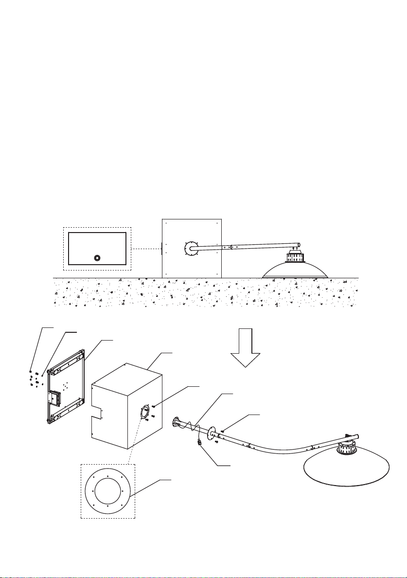
INSTALLATION, OPERATION & MAINTENANCE INSTRUCTIONS
Installation
Alwaysensureyouselectthecorrectxingaccessories
which suit the particular material you are attaching to, if
in doubt please discuss with your local retailer or local
hardwarestore.Thisheaterisnotdesignedforuse
within1moraboveawatersource.Allinstallationsmust
meet the requirements of Australia Standard AS/NZS
3000:2007.
Ensure that the heater is not positioned directly in front
of a power point or directly above or below a power
pointorswitch.
This heater is not designed to be used with 3rd party
timerorprogrammablesystem.
WARNING:Fireriskexistsifthisheateriscoveredby
or positioned close to curtains or other combustible
materials.
NOTE: When using this heater outside ensure that it is
connecteddirectlytoanoutdoorpowerpoint.
The electrical system of this heater must be connected
with an automatic 30mA circuit breaker and/or residual
currentdevice(RCD).Ifuncertainhaveaqualied
electrician check your electrical system before
installationand/oruse.
Allelectricalconnectionsaremadeinadryarea.
Outdoor power points must be weatherproof and
installedbyaqualiedelectrician.
When not in use ALWAYS store this heater in a safe,
securelocationwhichisnotaectedbywind,likea
garageorsimilarfullyenclosedarea.
If this heater can not be stored as directed above it is
highlyrecommendedthattheoorbracketsbeusedand
theheaterbermlysecuredtotheoor.Alwaysensure
thatthecorrectfasteningsareusedforthetypeofoor
the brackets are being attached to, if unsure discuss
withyourlocalhardwarestore.
Sitro Group Australia Pty Ltd is not responsible for
incorrectlychosenxingaccessoriesoranydamage
whichmaybecausedbyanincorrectlyttedheater.
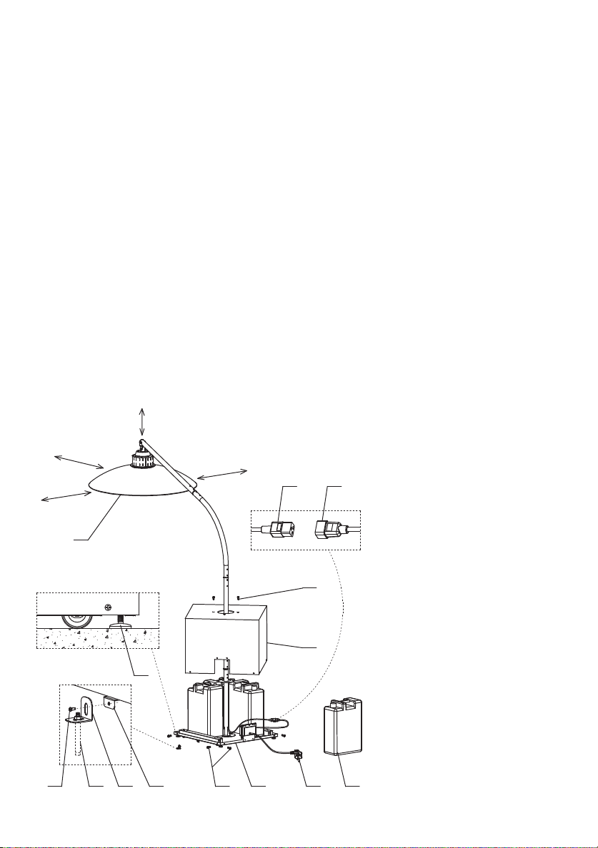
Position
Ensurethisheaterispositionedonsolid,stableat
ground.
Please ensure adequate distance to walls, ceiling, eaves
as noted;
- Minimum distance between top of heater and
ceiling/eave – 300mm
- Minimum distance to a wall or pole, for rotating
heater – 2000mm
This is to allow the heater head to rotate left and right
- Minimum distance to a combustible surface like a
timber wall – 1000mm
- Minimum height of heater head to be 1800mm above
theoor

32
SPECIFIC SAFETY INSTRUCTIONS
WARNING
Do not use the heater in areas where there is a risk of
explosionorrefromammablegases.Ensurethat
theheatingareaiskeptclearofcombustiblematerials.
Do not use the heater in damp areas, without suitable
ventilation.Thisheaterisnotdesignedforusewithin1m
oraboveawatersource.Donotplacewithinonemetre
(1m)ofanywatersource.Donotplacedirectlybelowor
aboveanypowerpointsorswitches.
WARNING:Fireriskexistsifthisheateriscoveredby
or positioned close to curtains or other combustible
materials.
• Thisheaterisintendedfordomestic/householduse
only.
• Alwaysensurethatthisheaterisinstalledasperthe
requirements noted in Australian Standard AS/NZS
3000:2007.
• Alwayskeepheateratleastonemetre(1m)from
combustiblematerials.
• DONOTlocatethisheaterdirectlybeloworabovethe
powersupplysocketorswitch.
• DONOTusethisheaterineitherabathroom
orensuite.
• DONOTusea3rdpartytimer,orprogrammable
systemwiththisheater.
• DONOTcleantheheaterwhiletheheaterisonor
pluggedintothemainspowersupply.
• DONOTtouchanypartoftheheaterwhileon,hot
surfacesmayburn.
• DONOTusetheheaterasadryer.
• DONOTattempttomodifytheheater,powercord,
powerplugorthesuppliedaccessoriesinanyway.
• DONOTexposetheheatertorain,water,orusein
dampwetconditions.
• NEVERcoverthisheater.
• NEVERcarrytheheaterbyitspowersupplycord.
• NEVERusewiththepowercordcoiled,bundledupor
tiedup.Alwaysextendfullybeforeuse.
• NEVERusetheheaterifanypartofitisdamaged.
• Ensurethattheheaterisdisconnectedfromthemains
supplywheninstalling,cleaningormoving.
• Ensurethisheaterisnotleftonwhenunattended.
• Ensuretheheaterisnotusedinareaswhere
ammablegasesarepresent,e.g.paint,petroletc.
• AlwaysturntheheaterOFFattheunitswitchand
the power point switch when not in use for extended
periodsoftime.
• Alwaysallowtheheatertocool,aboutone(1)hour
aftertheheaterhasbeenturnedo,beforecleaning
theheater.
• Alwaysensurethatthepowercordisfullyextended
andNOTincontactwithanypartoftheheater.
• Alwaysensurethattheheateriskeptcleanandfree
fromdust.
•Onlyuseheaterwhenfullyassembledandwiththe
SUPPLIEDwaterorsandcontainersfull.
•Onlyuseheaterwhensecurelymountedtothe
suppliedstandandtheheaterisfullyassembled.
• DONOTusewithin1metreofaswimmingpoolor
spa.
• NEVERallowchildren3yearsto8yearstoswitchthis
heaterONorplaywithremotecontrol.
• NEVERallowchildren3yearsto8yearstoplugin,
regulate heater, clean heater or perform maintenance
onthisheater.
• DONOTuseheaterasaclothesdrierortoweldrier.
•Removetheremotecontrolbatterieswhennotusing
theheaterforlongtime.
•Choosethesamespecicationbatterywhenreplacing
the remote control batteries, otherwise it may cause
remotecontrolnotwork,thereforeaectingthenormal
useoftheheater.
•Theremotecontrolfunctionislineofsightandmay
not operate is something or someone is in the way of
thesignal.
•Replacingthebatteriesregularlyissuggestedto
ensure the normal use and operation of heater and
accessories.
•Ifthemainsconnectionplugorpowercordbecomes
damaged it must be replaced with a complete
assembly that is identical to the original, and this must
be replaced by the manufacturer or an authorised
servicecentreorsimilarqualiedpersonsinorderto
avoidahazard.
• Ifheaterisbeingleftunattendedwhennotinuse,
itishighlyrecommendedtheoorbracketbeused
andtheheaterbermlysecuredtotheoor.Always
ensurethecorrectfastenerisusedforthetypeofoor
the bracket is being attached to, if unsure discuss with
yourlocalhardwarestore.
WARNING - In order to avoid over heating, DO NOT COVER the heater.
This logo/symbol means DO NOT COVER.

54
Heater EH714
Voltage 220-240VAC50Hz
Input Wattage 2000-2400W
Unassembled unit weight 50Kg(inc.base)
Fullyassembledunitweight 150Kg
IP Rating IP 24
Lamp TA: 20 - 25°C
MAX 6W
Remote control batteries
(not supplied) 2 x AAA
Heaterspecicationscanbefoundonthedatalabel.
IMPORTANT
Thisproductisttedwithasealedelectricalconnection
plug that is compatible with the heater, the mains supply
for Australia and meets the requirements of international
standards.Thisheatermustbeconnectedtoasupply
voltagethatisequaltothatstatedontheratinglabel.
If the mains connection plug or power cord becomes
damaged it must be replaced with a complete assembly
that is identical to the original, and this must be replaced
by the manufacturer or an authorised service centre
orsimilarqualiedpersonsinordertoavoidahazard.
Always follow the Australian requirements for connection
tothemainssupply.Ifindoubtalwaysconsultaqualied
electrician.
Technical Specification
ELECTRICAL DATA
COMPONENTS & ACCESSORIES
COMPONENTS
No. Part Name
1 Heater Head
2 Closed End Nut M8
3Spring Hook
4Screws M8*50
5Screws M8*55
6Tube Cover
7Cord Brushing
8Upper Tube
9FemaleCordConnector
10 Tube Connector
11 Screws M6*12
12 Curled Tube
13 Upper Rotary Tube Connector
14 Middle Tube
15 Spring Washer
16 Base Cover
17 Screw M4*20
ACCESSORIES
Accessory Name Qty
Spring Hook 1
Screws M6*12 10
Water Tank 4
Spring Washer M6 4
Foot 4
Remote Control 1
FloorBracketMount 1
FloorBracket 1
FloorBracketConcrete
Expansion Bolt 1
No. Part Name
18 Heater Bracket Plate
19 Lower Tube
20 Base
21 Water Tank
22 Spring Washer
23 Male Cord Connector
24 Foot
25 Power Cord & Plug
26 Junction Board
27 Control Panel
28 Remote Control
29 FloorBracketMount
30 FloorBracket
31 FloorBracketConcreteExpansion Bolt
32 Heater Steel Plate
33 Screw knob

54
ACCESSORIES
Accessory Name Qty
Spring Hook 1
Screws M6*12 10
Water Tank 4
Spring Washer M6 4
Foot 4
Remote Control 1
FloorBracketMount 1
FloorBracket 1
FloorBracketConcrete
Expansion Bolt 1
Note: Remove all transit packaging and protection
material before starting to assemble. Dispose of in
an environmentally friendly way.
Note: In order not to damage or scratch parts/components
it is recommended that a blanket is place on the ground
beforeunpackingthisheater.Giventhesizeandweightof
this heater it is recommended that 2 people are required
forassembly.
Note: Only tool required is a “Phillips” cross head screw
driver.
Heater Head and Stand, FIG A
To avoid scratching lay parts/components on a blanket
forassembly.
1. HooktheCarbineer(#3)ontoboththetopofthe
HeaterBracketPlate(#18)&HeaterSteelPlate(#32).
2. PutCordBushing(#7)&TubeCover(#6)ontothe
openendoftheUpperTube(#8).
3. PulltheexcesspowercordbetweentheHeater
Head(#1)&UpperTube(#8)intotheothertubes.
Do not make too tight, have enough excess cord
tobeabletoputyourngersbetweentheexcess
cordandthespringextension(#3)thiswillensure
thattheHeaterHead(#1)isfreetomovewhenyou
standitup.
4. SecurepowercordintoclamponHeaterSteel
Plate(#32).
5. FixtheCurvedTube(#12)totheUpperTube
assembly,usingtheTubeConnector(#10)
&ScrewsM6*12(#11).
6. FixtheMiddleTube(#14)totheCurvedTube
assembly,usingtheTubeConnector(#10)
&ScrewsM6*12(#11).
7. FixtheLowerTube(#19)totheMiddleTube
assembly using the Upper Rotary Tube Connector
(#13)&ScrewsM6*12(#11)&ScrewKnobM6*16
(#18).
ASSEMBLY INSTRUCTIONS
6732
8
1
3
18
11
12
11
13
11
33
11
10
10
19
14
FIG A

76
Heater Base, FIG B
1. Unscrewallofthe8ScrewsM6*12(#11)andthe2
ScrewsM4*20(#17)whichattachtheBaseCover
(#16)totheBase(#20)andremovetheBase
Cover(#16).
2.Screwtheoorbracket(#30)totheoorbracket
mount(#29)whichislocatedonthesideof
base(#20)usingscrewM6*12(#11).
3.Removeall4oftheemptyWaterTanks
(#21),llthemfullwithwaterforuselater.
16
17
12
20
11
FIG B
3031 29
11

76
11
19
16
20
11
22
11
26
23
FIG C
Heater Base, FIG C
3. LaytheBaseCover(#16)onitssidewiththecutout
visibleandtotheleft.
4. Slidethepowercordandassembledtubes(#19),
throughtheBaseCover(#16)carefully.Makesure
thepowercordandMaleCordConnector(#23)are
not damaged when getting through the hole on the
BaseCover(#16).FixtheLowerTube(#19)ontothe
JunctionBoard(#26),whichispre-installedonthe
topoftheBaseCover(#16)with4ScrewsM6*12
(#11).
5. DetachtheJunctionBoard(#26)fromtheBaseCover
(#16)byunscrewingandremovingthe4ScrewsM6*12
(#11),nowslidetheBaseCoveruptheassembled
poles so that you can access the bottom bracket on the
LowerTube(#19).Usecautionwhenslidingthebase
cover, as you do not want to scratch the assembled
poles, suggest 1 person lift the assembled poles slightly
whiletheotherpersonslidesthebasecover.
6. ScrewtheLowerTube(#19)ontotheBase(#20)
using4ScrewsM6*12(#11)andSpringWashersM6
(#22).
7. Carefullyslidethebasecoverdownsothatitisatthe
base,donottrapthepowercordorconnector.

98
Heater Base, FIG D
1. Carefullystandtheheaterup.1personwillneedto
supporttheheater.LifttheBaseCover(#16)up
andplacethe4FULLWaterTanks(#21)intothe
base.
2. ResttheBaseCover(#16)ontopofthe4FULL
watertanks.
3. ConnecttheMaleandFemalePowerCord
Connectors(#23	)securely.
4. PositionthePowerCordandConnectorssothat
they will not get caught when the base cover is in
position.
5. PositiontheBaseCover(#16)ontotheBase(#21)
correctly and secure together by re-screwing the
8ScrewsM6*12(#11)andthe2ScrewsM4*20(#17)
whichwereremovedatstep1,FIGB.
6. SecuretheBaseCover(#16)ontotheJunction
Board(#26)with4ScrewsM6*12(#11).
7. Atthispointtheheaterwillsupportitsselfandthe
personsupportingtheheatercanletgo.
8. Thereare4wheelsunderthebase,withwhichthe
heatercouldbemovedfreely,thesedonotswivel.
9. Thereare4ScrewFeet(#24)ateachcornersunder
theBase(#20)tomaketheheatermorestable.
a. Toadjustthescrewfeetunscrew,anti-clockwise
untilrmagainsttheground,makingsureyou
doall4screwfeet.
b. Tomovetheheaterall4screwfeetwillneedto
bescrewedin,clockwise.
c. Onceheaterhasbeenre-locatedensurethat
you unscrew all 4 screw feet, anti-clockwise until
rmagainsttheground.
NOTE: If the heater is being left unattended when
notinuse,itishighlyrecommendedthattheoor
bracket(#30)beusedandtheheaterbermly
securedtotheoor.Alwaysensurethecorrect
fastener(#31)isusedforthetypeofoorthebracket
is being attached to, if unsure discuss with your
localhardwarestore.10.Onlyuseheaterwhenfully
assembled and with the SUPPLIED water or sand
containersfull.
10.Positiontheheateraspersteps8and9.Oncethe
correctpositionisfound,marktheoorthroughthe
holeinoorbracket(#30).
11.Drillholesuitablefortheselectedfastener(#31).
12.Screwtheselectedfastener(#31)throughtheoor
bracketandintotheoor,tightenrmly.
13.Ifyouneedtorepositiontheheaterloosenand
removethefastener(#31),moveheaterthenrepeat
steps10through12.
25kg
Water
20
1.0m
1.0m
1.0m
16
11
2511
1
23 9
0.3m
213031
24
29
11
FIG D

98
Heater Positioning
NOTE: If heater is being left unattended when not in
use,itishighlyrecommendedtheoorbracketbeused
andtheheaterbermlysecuredtotheoor.Always
ensurethecorrectfastenerisusedforthetypeofoor
the bracket is being attached to, if unsure discuss with
your local hardware store, refer to page 8 for details of
securing.
1. Onlyuseheateronat,level,solidground.
2. Positionheateratleast300mmfromtheeavelining
orceiling.
3. Onlyuseheateronthestandprovided.
4. Onlyuseheaterwhenfullyassembledandwiththe
SUPPLIEDwaterorsandcontainersfull.
5. Neverpositioninfront,aboveorbelowapower
point.
6. Ifheaterisfacinganotherverticalsurface,example–
wall,thegapmustbeatleast1metre.
7. Nevermountheaterwithin1metreofawatersource,
example–tap,pool,spaorwaterfeature.
8. Nevermountheaterintothewallorceiling.Only
mounttothestandprovided.
Controls, Built In & Remote
Once the heater has been turned on at the heater head,
this heater can then be operated either by the provided
remote control or by the built in controls in the heater
head.Theoperatingcontrols,Remote/Builtin,arethe
same.
To use the remote control;
-Slidebackotheremotecontrol
- Insert 2 x “AAA” batteries (Not Supplied)
-Slidethebackintoposition.
Using Heater, FIG E
Position heater and ensure that the screw feet are
againstthegroundandthattheheaterisstable.
1. Pluginto240VACwallsocketandturnON.
Note: All outdoor power points must be installed by
aqualiedelectricianandshouldbeofawaterproof
style.
2. PressMainSwitch”-”ontheheaterhead,thedigital
displaywillstartashingshowingthattheheateris
onstandby.
a.Theheatercannoweitherbeoperatedwiththe
remotecontrolorthebuiltinheatercontrols.
3. HeaterControls
a.Press“Mode”buttontoturnheateron.By
pressing the “Mode” button again you will change
theheatersetting.
i.Thiswillcyclethrougheachheatsetting
continually with each press of the “Mode”
button.
ii.Theselectedsettingwilldisplayonthebuiltin
display on the heater head
b.Press“Timer”buttontochoosethelengthoftime
theheaterwilloperatebeforeturningo.
i. Thetimercanbesetbetween0-9hours.
1.“0”meansthetimeriso.
c.Thedigitsofthepowersettingsandtimerwillbe
displayed as cycled: power settings for ten
seconds,timerashingforveseconds.
4. Pressbuttontoswitchon/otheBluetooth
speaker.
5. Press“Light”buttontoswitchon/otheLEDlight.
6. Toshifttheheatertostandbymode,pressOFF
button.Thedisplaywillstartashing”-”.
7. Toswitchotheheater,pressMainSwitchonthe
heaterheadaccordingly.
Bluetooth Pairing
To pair heater speaker with your Bluetooth compatible
music player/phone;
1. Pressandholdbuttonuntilyouheara
chime sound
2. Searchfor“HH-LY01”onyourdevice.
3. Selectandfollowthepromptsforpairing.
OFF MODE
HEAT
TIMERLIGHT
TIMERLIGHT
MODEOFF
27
28
FIG E

1110
Rotating Heater Head, FIG F
NOTE: Ensure you have a minimum of 2m clearance
to rotate the head otherwise the heater head will hit the
obstacle.
Warning:AlwayshavetheheaterturnedOFFbefore
rotatingtheheaterhead.
To rotate the heater head;
1. Loosenthescrewknob(#33),donotremove.
2. Slowlyandgentlymovethetoppartofthestandand
heaterheadleftorright.
3. Oncenewpositioniscorrecttightenthescrew
knob(#33).
Cleaning
Always ensure that the heater has been left for one (1)
hourtocoolbeforecleaning.
1. Turnoanddisconnectfrommainspower,
allowtocool.
2.Wipeunitoverwithadampcleansoftlintfree
cloth.
3.Forstubbornmarksyoucanuseamilddish
washing solution on a damp clean soft lint free
cloth.
NEVERallowwateroramilddishwashingsolutionto
enterordripontotheheater.
NEVERusesolvents,e.g.Petrol,Toluene,Methylated
Spirits etc to clean the heater, as these will damage the
surfacenishandmaycausearewhenunitisnext
used.
Replacing Parts
If replacement parts are required, including light,
bluetooth speaker or digital display, please contact
CustomerServiceforyourclosestServiceAgent.
Therearenouserserviceableparts.Allservicingand
replacement parts must be installed by a service agent
orqualiedpersontoavoidelectricalhazards.
FIG F
33

1110
WARRANTY STATEMENT
GASMATE BARBEQUES & ACCESSORIES
PRODUCT RANGE
SITROGROUPAUSTRALIA(S.G.A.)warrantsthe
purchaser of this product against defects in workmanship
and materials for the following periods from the date of
purchase:
Fordomesticusethistableapplies:
Stainless steel components 5 years (surface oxidization
excluded)
Enamel components 5 years (chips excluded)
Powder coated components 1 year
Burners 3 years (surface rust excluded)
Cast iron cooking plates
and burners
3 years (surface rust excluded)
Valves 3 years
Ignition 1 year
All other items 1 year
This warranty is not transferable to a subsequent
purchaser if the product is sold by the original purchaser
duringthewarrantyperiod.
If a warranty fault appears within the warranty period,
S.G.A.reservestherighttoreplaceorrepairtheproduct.
IntheeventthatS.G.A.choosestoreplacetheproduct,
thisoriginalwarrantywillexpireattheoriginaldate.
If the product includes various accessories or
components, only the defective accessory or component
willbereplacedorrepaired.
S.G.A.reservestherighttoreplacedefectiveparts
of the product with parts and components of similar
quality, grade and composition where an identical part or
componentisnotavailable.
Products presented for repair may be replaced by
refurbished products of the same type rather than being
repaired.Refurbishedpartsmaybeusedtorepairthe
products.
Tomakeawarrantyclaim,rstcontactS.G.A’sCustomer
ServiceLineonthecontactnumberbelow.
The purchase receipt for this product is to be retained
and must be presented if making claim under the terms
ofthisS.G.A.warranty.
Warranty repairs are free of charge, provided the product
is delivered to our Service Department at 33-35 Lionel
Road,MtWaverley,Victoria,3149ortooneofour
AuthorisedServiceAgents.
If a warranty fault is found the freight cost will be credited
totheowner.
If no fault is found the product will be returned and any
costs associated with the service will be charged to
theowner.
Productssentfreightforwardwillnotbeaccepted.In
most cases the defective accessory or component only
willneedtobereturned.Theproductorpartofthe
product being returned must be adequately protected in
abox.
S.G.A.willnotberesponsibleforanyin-transitlossor
damage.
This warranty does not apply to any defect, deterioration,
loss,injuryordamageoccasionedbyorasaresultof
misuse or abuse, negligent handling or storage, normal
wear and tear or if the product has not been installed
andusedinaccordancewithS.G.A.’sinstructions,
recommendationsandspecicationsoriftheproduct
hasbeensubjectedtoabnormalconditions.Thewarranty
does not apply to blockages caused by insects or living
organisms.
The warranty is void if there is evidence of the product
beingtamperedwithbyunauthorisedpersons.
The warranty does not extend to installation or
disconnectioncosts.
Our goods come with guarantees that cannot be
excludedundertheAustralianConsumerLaw.Youare
entitledtoareplacementorrefundforamajorfailureand
for compensation for any other reasonably foreseeable
lossordamage.Youarealsoentitledtohavethegoods
repaired or replaced if the goods fail to be of acceptable
qualityandthefailuredoesnotamounttoamajorfailure.
Thebenetsofthiswarrantyareinadditiontoanyrights
andremediesimposedbyAustralianStateandFederal
legislationthatcannotbeexcluded.
Forwarrantyclaims,service,sparepartsorproducts
information in Australia, please call SITRO GROUP
AUSTRALIA Pty Ltd on the Customer Service Line
1300174876.
Register your Warranty online at
www.gasmate.com.au
A receipt or proof of purchase is required and must be
keptforyourrecords.Note:Ifyoudonothaveinternet
access call our customer service team on 1300 174 876
CONTACT DETAILS
Sitro Group Australia Pty Ltd
33-35LionelRoad,Mt.Waverley
Victoria3149,Australia.
Tel (+613) 9543 9533
Fax(+613)95439839

For any queries or assistance call
Customer Service
(Australia Only)
1300 174 876
Hours of operation:
Monday to Friday 8am - 5pm EST
Do not return to place of purchase.
Keep your purchase receipt, this will be required to
make any claims under the 12 month warranty.
Table of contents
Other Gasmate Electric Heater manuals

Gasmate
Gasmate GM135-010 User manual

Gasmate
Gasmate GM135-019 User manual

Gasmate
Gasmate HELLION GM135-041 User manual

Gasmate
Gasmate EH431 User manual

Gasmate
Gasmate GM135-045 User manual

Gasmate
Gasmate GM135-044 User manual

Gasmate
Gasmate EH240 User manual

Gasmate
Gasmate EH325 User manual

Gasmate
Gasmate GM135-008 User manual

Gasmate
Gasmate EH611X User manual
Popular Electric Heater manuals by other brands

Hoffman
Hoffman nVent DAH1002A manual

Chromalox
Chromalox PD422-4 Installation and operating instructions

Frico
Frico Elztrip EZ100 Original instructions

DeLonghi
DeLonghi Electric oil filled heater instructions

e-Flame USA
e-Flame USA FS2213B owner's manual

Harvia
Harvia DELTA COMBI Instructions for installation and use