Gate Bure Standard EL 56-312T User manual

BureTM
PMS 322 C
Bure Standard EL 56-312T
Bure S EL 56-302T
Walker
Instructions for use

Bruksanvisning Bure
Justering av handtag
Handtagen justeras till önskad position genom att:
Ratt lossas, justera in handtag
Ratt låses
Upp
Ned
Min
Max
Höjning/sänkning
av stativ (El)
Önskad höjd justeras med hjälp
av fjärrkontrollen
Pil <UPP> resp. Pil <NED>
Breddning av stativ
(endast Bure Double)
Önskad bredd (max/min) justeras
med hjälp av fjärrkontrollen:
Håll in Pil <vänster> = Minimal
breddning av benstativ.
Håll in Pil <höger>
= Maximal breddning av
benstativ.
Justering av armstödsplattor (Hö/Vä)
För optimalt stöd kan Armstödsplattor breddjusteras:
Ratt lossas, armstödsplattas läge justeras. Ratt låses
Låsning av hjul
Hjulen låses genom att fotbroms aktiveras.
Upplåsning av hjul
För att lossa bromsen – återställ.
1. Uttag för batterikontakt
2. Uttag för stickpropp
(OBS! För att IP-klassning ska gälla så ska
stickpropp ALLTID vara ansluten till styrbox)
3. Uttag för fjärrkontroll
4. Uttag för ställdon - höj/sänk
5. Uttag för ställdon - breddning (Endast Bure Double)
OBS! Var noga med att kontakter ansluts till rätt uttag eftersom detta annars
kan skada ställdon.
Laddning av batteri ska ske då gåbordet inte används.
(Batteriet kan aldrig överladdas.) Laddning görs genom
att stickpropp ansluts till eluttag.
Innan första användningen så bör batteriet
laddas 24 timmar.
Kopplingsschema Styrbox
(Bure El/Bure Double/Bure Extra)
Laddning av batteri
(Bure El/Bure Double/Bure Extra)
2
3
4
1
5
Adjusting
the handles
To adjust handles to
the desired position;
loosen screw, adjust
handle, tighten screw.
Dear User,
Congratulations on obtaining a Bure Walker! These
instructions provide important information on how
to use the walker and how to maintain it.
All of us here at GATE Rehab Development hope
you enjoy using your new product. If you have any
comments, questions or points of view, please
contact us on +46 (0)371 318 00.
Raising and lowering the frame
Adjust the height with
the aid of the remote
control UP and
DOWN arrows.

Bruksanvisning Bure
Justering av handtag
Handtagen justeras till önskad position genom att:
Ratt lossas, justera in handtag
Ratt låses
Upp
Ned
Min
Max
Höjning/sänkning
av stativ (El)
Önskad höjd justeras med hjälp
av fjärrkontrollen
Pil <UPP> resp. Pil <NED>
Breddning av stativ
(endast Bure Double)
Önskad bredd (max/min) justeras
med hjälp av fjärrkontrollen:
Håll in Pil <vänster> = Minimal
breddning av benstativ.
Håll in Pil <höger>
= Maximal breddning av
benstativ.
Justering av armstödsplattor (Hö/Vä)
För optimalt stöd kan Armstödsplattor breddjusteras:
Ratt lossas, armstödsplattas läge justeras. Ratt låses
Låsning av hjul
Hjulen låses genom att fotbroms aktiveras.
Upplåsning av hjul
För att lossa bromsen – återställ.
1. Uttag för batterikontakt
2. Uttag för stickpropp
(OBS! För att IP-klassning ska gälla så ska
stickpropp ALLTID vara ansluten till styrbox)
3. Uttag för fjärrkontroll
4. Uttag för ställdon - höj/sänk
5. Uttag för ställdon - breddning (Endast Bure Double)
OBS! Var noga med att kontakter ansluts till rätt uttag eftersom detta annars
kan skada ställdon.
Laddning av batteri ska ske då gåbordet inte används.
(Batteriet kan aldrig överladdas.) Laddning görs genom
att stickpropp ansluts till eluttag.
Innan första användningen så bör batteriet
laddas 24 timmar.
Kopplingsschema Styrbox
(Bure El/Bure Double/Bure Extra)
Laddning av batteri
(Bure El/Bure Double/Bure Extra)
2
3
4
1
5
Left and right adjustment of armrests
The armrests can be adjusted sideways for optimal
support; loosen screw, adjust armrest, tighten screw.
Locking castors
Depress the foot brake to set it and lock the castor.
Unlocking castors
Press down on the protruding part of the brake to
release it.

2
3
4
1
Control box wiring
Control box wiring
LEDs on control box and battery
Remove the control box cover to make
the connections as described below.
Use a screwdriver or similar; refer to
the special labels on the control box.
1. Socket for the raise/lower actuator.
NOTE! Make sure that plugs are
connected to the correct sockets
otherwise the actuators can be
damaged.
2. Remote control socket.
3. Battery terminal socket.
4. Plug socket. NOTE! The plug
must ALWAYS be connected to
the control box for IP protection
to be valid.
• Connectplugto230Vwallsocket.Chargingbegins
automatically and the battery LED flashes green.
• Makesurethebatteryisfullychargedbeforeusingforthe
first time. It takes around 25 h to fully charge the battery.
• Werecommendthatthebatteryplugberemovedfromthe
control box if the product will be out of use for an extended
period (more than three weeks). This eliminates the risk of
ruining the battery as the control box always uses a small
quantity of electricity even when the walker is not in use.
• Controlbox–greenlightwhenpowerisavailablefrom
battery/mains socket.
• Battery:
•TheLEDashesgreenduringcharging.
•TheLEDshowsaconstantgreenlightwhenthebattery
is fully charged.
•Whenthebatteryisinnormalstate/inoperation,theLED
flashes green at REGULAR intervals of 0.5 s ON, 4 s OFF.
•Whenthebatteryrequirescharging(remainingcharge
<25%) the LED flashes orange/red at REGULAR
intervalsof–0.5sON,4sOFF.
NOTE! The battery has an in-built function that automatically
switches it off when remaining charge is <20%. The LED is then
extinguished. The battery must now be fully charged before the
electronics can be used again.

Maintenance
Recommended at least once per year.
Check that Action
General
The walker feels firm/free from play.
The walker does not rattle during
manoeuvres.
The walker is level and all of its castors
are in contact with the floor.
The walker is not dirty.
Armrests
Armrests are intact and clean.
Armrest widening is functional.
Handle
Grips are not damaged/dirty.
Handle adjustment is functional.
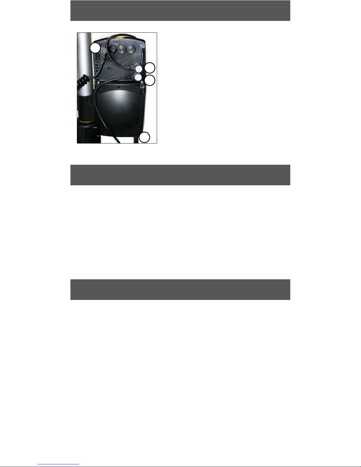
Battery
Checkthatthechargingcableis
connected to the control box.
Checkthattheremotecontrolis
connected to the control box.
Checkthatconnectionsaremade
according to the wiring diagram.
Checkthatthebattery,actuatorsand
control box are not loose.
Height adjustment
Raising and lowering are functional.
The walker feels stable at maximum
settings.
There is no play between the vertical
frame and bottom frame.
Height adjustment clamps lock.
The electric actuator fitting must be free
from play.
Height adjustment via remote control is
functional. The electric actuator must run
smoothly at a constant speed.
Frame parts
There is no mechanical damage.
There are no scratches.
End plugs/lower frame fitted.
Castors/brakes
Castorsrolleasily/treadnotdamaged.
The castors are firmly fastened to the
lower frame.
Castorbrakesfunctionalonallcastors.
Handbrake functional.
Cleanwithlukewarmsoapsolutionor
alcohol-based cleaning agent
(no petroleum products).
Clean;replaceifdamaged.
Fit lock screws/plates as required.
Cleanwithlukewarmsoapsolution
(no petroleum products).
Replace handle grips.
Fit lock screws/plates as required.
Fit new charging cable; this must always
be connected to the control box (IP65
protection).
Connectortnewremotecontrolas
required.
Refer to the wiring diagram in the
Technical manual.
Tighten; replace with new fasteners as
required.
Fit new guide sleeves (in frame) or end
plugs (in chrome tubes) as required.
Tighten all lock bolts.
Replace clamps.
Tighten the attachment fitting concerned;
replace bolts/lock nuts
as necessary.
Checkthatthebattery/remotecontrol/
actuator are connected in accordance
withthewiringdiagram.Chargethe
battery.Contactcustomerservices.
If damage is present, contact GATE’s
customer services.
Touch up as necessary.
Fit new end plugs.
Cleanorreplacecastors.
NOTE!Castorsarealwaysxedtothe
lower frame with thread locker or lock
nuts. Do not dismantle the castors;
replace the whole castor assembly
instead.
Tighten the castor bolt and fit locking nut
or use thread locker (depends on model).
Replace castor assembly.
Adjust the brake or fit new castors.

Standard EL
Part No.
56-312T
Width
78 cm
Max user weight
150 kg
Length
80 cm
Height
91–131cm
Armrest/internal dimension
25–50cm
S EL
Part No.
56-302T
Width
66 cm
Max user weight
150 kg
Length
79 cm
Height
91–131cm
Armrest/internal dimension
30–45cm
General maintenance advice
• Cleanthewalkeranditsarmrestscleanasnecessary;
Wipe using a soap solution/surface disinfectant.
• Theproductmaybecleanedinatunnelwasherorsimilaras
electrical systems have IP65 protection. However, the product
is not corrosion proof which means washing by machine may
reduce its lifetime.
• Replacedamagedpartsimmediately;mustbedoneby
experienced personnel.
• Theproductisonlyintendedforindooruse.
Technical specifications
Dimensions apply to walkers with 125 mm castors.
CEmarkedaccordingtoMDD93/42/EEC.
Tested and approved according to EN-11199-3/2005
2014-06-27, 2
PMS 322 C
DIN PARTNER I VÅRDEN
Would you like to know more?
Contactusat:
Tel:+4637131800
Gate Rehab Development AB
Industrigatan 2 | SE-330 21 Reftele
PMS 322 C
DIN PARTNER I VÅRDEN
YOUR HEALTHCARE PARTNER
This manual suits for next models
1
Table of contents
Other Gate Medical Equipment manuals

Gate
Gate Bure Space User manual

Gate
Gate Easy SoftBack 56-270 User manual

Gate
Gate Mover Aqua 53-301 User manual

Gate
Gate Amfibi Double 56-203DB User manual

Gate
Gate Bure Double 2.0 56-303 User manual

Gate
Gate Amfibi Double HighBack 56-275 User manual

Gate
Gate Bure Ortho GAS, 56-318 User manual

Gate
Gate Bure Ortho 56-317T User manual

Gate
Gate Bure Double 2.0 56-303 User manual

Gate
Gate Bure XL User manual