Gate Bure Double 2.0 56-303 User manual

1
Technical manual
digital
Bure Double 2.0 56-303
Bure
Walker
™

1
2
3
4
8
6
7
9
10
11
12
22
21
15
201819
16 17
14
13
2

3
157-306 Armrestpad left
57-305 Armrestpad right
258-365 Frame/Armrest
357-041-3 Holder, Remote-
control (TH7)
457-369 Clamp/Battery (alu)
57-370 Plate Clamp/Battery
(alu)
558-376 Battery, TiMotion
658-377 Actuator, TiMotion
758-373 Controlbox 220V,
TiMotion
58-373-1 Controlbox 110V,
TiMotion
858-366 Vertical frame
58-335 Telescopic Innertube
incl. Bronzebearing
958-358 Sideplate (2x) alu
10 58-356 Aluprofile, widening
11 58-378 Actuator, widening
(TiMotion)
12 58-364 Circular plate
13 58-352 Cross section
14 58-302 Bearing (x2) Cross
section
15 58-353 Turn axle, beam
16 57-776 Cover, Wheel
57-775 Washer, wheel
17 58-360 Cover, Wheelplate
(PA)
18 58-354 Wheel mount beam
19 57-051 Wheel 75mm
57-319 Wheel 100mm
57-049 Wheel 125mm
20 58-379-L Bottom beam, left
58-379-R Bottom beam, right
21 Linking arm, right
22 Linking arm, left
Part no. Description
Manual brake, 2handles
Manual brake, 1handle
56-333-DB Standing plate, Short
56-383-DB Standing plate, Long
56-334 Dripstand, Chromed
56-335 Holder for Dripstand
56-336 Oxygen tubeholder
56-337 Side support
56-338 Dripstand holder, Complete
Kneesupport
56-387 Wheel w brake 75 mm
56-358 Wheel w brake 100 mm
56-361 Wheel w brake 125 mm
57-361-L Armrestpad PUR left
57-361-R Armrestpad PUR right
58-374-2 Remote Control (TH7)
56-062 Remote Control PLUS, DB (TH10)
58-320 (-1, -2, -3) Cable/EUR (-UK, -US, -AUS)
58-326 (-1, -2, -3) Coiled Cable/EUR (-UK, -US, -AUS)
Replacement parts list
Accessories

4
Electrical system – Technical data
Actuator
Producer
Voltage
Push
Pull
Selflocking push
Current
Colour
Stroke
Mounting dim
Encapsulation
IEC 60601-1 3rd revision
Controlbox + Battery
Producer
Voltage
Capacity
Encapsulation
Colour
Electrical safety
IEC 60601-1 3rd revision
Lift
T-Motion
24V
2000N
2000N
1000N
4,6 A
Black
400mm
605mm
IP66
Widening
T-Motion
24V
1000N
1000N
1000N
2,8 A
Black
55mm
167mm
IP66
Remote Control Plus
T-Motion
24V
2,0 AH
IP66
Black
Class II (Doubleinsulation)
**1. Service indicator – flashes red after 11 months’ operation.
Constant light (red) after 12 months’ operation. The indicator
is a reminder to review the maintenance instruction (see
Instructions for Use/Technical Manual. This should be done at
least once every 12 months.
Reset: hold down buttons <2a> + <2b>
for at least 30 seconds.
**The indicator will go out around 30 seconds after the remote control is
activated (battery conservation function).
2a 2b
1

5
Battery charging
LED on controlbox and battery
• Connect plug to 230V wall socket. Charging begins automatically and the battery LED
flashes green.
• Make sure the battery is fully charged before using for the first time. It takes around
25 h to fully charge the battery.
• We recommend that the battery plug be removed from the control box if the product
will be out of use for an extended period (more than one week) or if the battery is
switched off by means of the ON/OFF switch. This eliminates the risk of disabling the
battery as the control box always uses a small quantity of electricity even when the
walker is not in use.
• Control box – green light when power is available from battery/mains socket.
• Battery:
• The LED flashes green during charging.
• ON/OFF: To use the product, press ON.
• The green lamp will begin to flash.
• Use the OFF button (hold down for 5 s) to switch off the
battery if the product will not be used for an extended period.
• The LED will shows a constant green light when the battery
is fully charged.
• When the battery is in normal state/in operation, the LED
• flashes green at REGULAR intervals, namely 0.5 s ON, 4 s OFF.
• When the battery requires charging (remaining charge <25%) the LED will flash
• orange/red at REGULAR intervals, namely 0.5 s ON, 4 s OFF.
NOTE! The battery has an in-built device that automatically switches it off when
remaining charge is <20%. The LED is then extinguished. The battery must now be
fully charged before the electronics can be used again.
1 2
3
4
5
Control box wiring
Remove the control box cover to make the connections as
described below. Use a screwdriver or similar; refer to the
special labels on the control box.
NOTE! Make sure that plugs are connected to the correct
sockets otherwise the actuators can be damaged.
1. Socket for the height adjustment actuator.
2. Socket for the width adjustment actuator.
3. Remote control socket.
4. Battery terminal socket.
5. Plug socket (NOTE! Plugs must ALWAYS be connected
to the control box for IP classification to be valid).

6
Maintenance (recommended at least once per year)
Check that Action
General
The walker feels firm/does not feel loose.
The walker does not rattle during manoeuvres.
The walker is level and all of its castors are in
contact with the floor.
The walker is not dirty.
Arm rests
Arm rests are intact and clean.
Arm rest widening is functional.
Handle
Grips are not damaged/dirty.
Handle adjustment is functional.
Battery
Check that the charging cable is connected
to the control box.
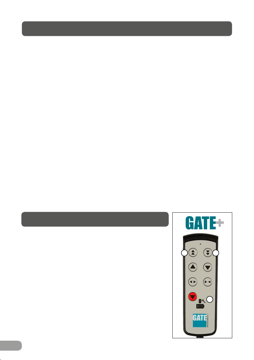
Check that the remote control is connected to
the control box.
Connect or fit new remote control as required.
Check that the battery, actuators and control box
are not loose.
Height/width adjustment
Raising and lowering are functional.
The walker feels stable at maximum settings.
There is no looseness between the vertical frame and
bottom frame.
Height adjustment clamps lock.
The electric actuator must not feel loose.
Height adjustment via remote control is functional. The
electric actuator must run smoothly at a constant speed.
Frame parts
There is no mechanical damage.
There are no scratches.
End plugs/lower frame fitted.
Castors/brakes
Castors roll easily/tread not damaged.
The castors are tightly fastened to the lower frame.
Castor brakes functional on all castors.
Handbrake functional.
Clean with lukewarm soap solution or alcohol-based clea-
ning agent
(no petroleum products).
Clean; replace if damaged.
Replace lock knob.
Clean with lukewarm soap solution (no petroleum products).
Replace handle grips.
Fit lock knobs/plates as required.
Fit new cable; this must always be connected to the
control box (IP65 classification).
Connect; replace with new remote control as required.
Refer to the wiring diagram in the Technical manual.
Tighten; replace with new fasteners as required.
Fit new guide sleeves (in frame) or end plugs
(in chrome tubes) as required.
The technical manual shows the design and which faste-
ners must be checked. Contact the distributor if the parts
cannot be tightened.
Replace clamps.
Tighten the attachment fitting concerned; replace bolts/
lock nuts as necessary.
Check that the battery/remote control/actuator are
connected in accordance with the wiring diagram.
Charge the battery. Contact customer services.
If damage is present, contact GATE’s customer services.
Touch up as necessary.
Fit new end plugs.
Clean or replace castors (NOTE! Castors are always fixed
to the lower frame with thread locker or lock nuts. The
castors are sealed and we do not recommend their
dismantling; instead, replace the whole castor assembly.
Tighten the castor bolt and fit locking nut or use thread
locker (depends on model).
Replace castor assembly.
Adjust the brake or fit new castors.

7
56-303
Gåbord Double 2.0
General safety/maintenance advice
Warranty
ID label
The Bure Walker may only be used:
• as a WALKING AID / STAND-UP AID.
• INDOORS on HARD, LEVEL surfaces.
Before use, always check that:
• the product feels firm, secure and stable
• harnesses, belts and attachments are intact and undamaged
Wipe the walker and its armrests clean as necessary; use soap solution/surface
disinfectant. Be aware of battery charge status (LED) – charge as necessary.
We provide two years’ warranty for manufacturing faults (does not apply to wear parts).
For further information or enquiries please contact:
1. Uttag för batterikontakt
2. Uttag för stickpropp
(OBS! För att IP-klassning ska gälla så ska
stickpropp ALLTID vara ansluten till styrbox)
3. Uttag för fjärrkontroll
4. Uttag för ställdon - höj/sänk
5. Uttag för ställdon - breddning (Endast
Bure Double)
OBS! Var noga med att kontakter ansluts
till rätt uttag eftersom detta annars kan
skada ställdon.
Kopplingsschema Styrbox Laddning Batteri
Laddning av batteri
Laddning av batteri ska ske då gåbordet inte
används. (Batteriet kan aldrig överladdas.)
Laddning görs genom att stickpropp ansluts
till eluttag.
Innan första användningen så
bör batteriet laddas 24 timmar..
2
3
4
1
5
Skötsel • • •
Generell skötselinstruktion Åtgärd
• Torka av gåbord och armstödsplattor vid behov – använd tvållösning
• Produkten ska ALLTID kännas stabil
Om gåbordet lutar eller har missljud – tillkalla servicepersonal.
• Byt ut trasiga delar omedelbart – skall göras av kunnig personal
• För gåbord med elställdon – använd ALDRIG gåbordet under laddning.
• Kontrollera att styrrör (g) är åtdragna i överstativ (3).
Övriga instruktioner • • •
5
Gate Rehab Development AB
Industrigatan 2, SE-330 21 Reftele, Sweden
Tel: +46 (0)371 31800
info@gaterd.com
1. Part number
2. Product name
3. Date of manufacture
4. Max user weight
5. Serial number
6. EAN code
5
3
4
1
6
2
Recycling/Scrapping
When the product is no longer usable it should be recycled in accordance with legisla-
tion and regulations in the country concerned. All electrical parts including batteries
must be removed and recycled as electrical components. (Ask your local recycling
station for further information about how the different materials in the product (metals,
plastics, electronics) should be recycled).

8
2016-09-27, 3
Technical specications
Dimensions apply to walkers with 125 mm castors.
Part No. Product
Width
Max user
weight
Length Height Weight Armrest/
internal
dimension
56-303 64-95 cm 150 kg 87 cm 90-130 cm 40 kg 25-50 cm
CE marked according to MDD 93/42/EEC
SE Patent No. SE534997. Patent pending in other countries
PMS 322 C
DIN PARTNER I V
Å
RDEN
Would you like to know more?
Contact us at: Tel: +46 371 31800
Gate Rehab Development AB
Industrigatan 2 | SE-330 21 Reftele
YOUR HEALTHCARE PARTNER
87 cm
90 cm
64-95 cm
69-81 cm
25-50 cm
Table of contents
Other Gate Medical Equipment manuals

Gate
Gate Amfibi Double HighBack 56-275 User manual

Gate
Gate Bure Standard User manual

Gate
Gate Bure Standard EL 56-312T User manual

Gate
Gate Amfibi Double 56-203DB User manual

Gate
Gate Bure Standard GAS 56-311 User manual

Gate
Gate Bure Rise & Go DB 56-309 User manual

Gate
Gate Bure Ortho GAS, 56-318 User manual

Gate
Gate Bure Space User manual

Gate
Gate Bure Rise & Go 56-316 User manual

Gate
Gate Bure Double 2.0 56-303 User manual