GATEXPERT GA1000AC User manual

Sliding Gate Opener
User Manual
GA1000AC
Website: www.gatexpertstore.com
E-mail: sales@gatexpertstore.com

GA600AC Sliding Gate Opener User Manual
WARNING:
Always read this manual before installation, it contains important information
concerning installation, use, maintenance and safety.
Any operation not described in this manual is not permitted; incorrect use may damage
the product and even injure people and property.
Considering the possible dangers that may arise during the installation and use of the
gate opener, the installation must be carried out in strict compliance with building
construction standards and electrical operating procedures, in particular:
● Before starting the installation, check whether additional equipment or materials are
required to meet specific needs.
● Packaging materials must be handled in compliance with local regulations.
● Do not alter any parts except as described in this manual. Unexplained alterations may
cause malfunction. We are not responsible for any damage caused.
● Do not leak water or any liquid into the controller or other open devices. In such a case,
disconnect the power supply immediately. Continued use under such conditions is very
dangerous.
● When installing and positioning the motor, make sure that the power cord is unplugged
and the cover is removed before installing the motor on the mounting plate.
● The motor's operation involving electricity must be installed by a licensed professional.
● Do not install the product in an environment where there is an explosive atmosphere or
any risk of flooding.
● Use only original parts for all maintenance or repairs. If you use parts made by other
suppliers, we refuse to be responsible for the safety of the automatic control of this product.
● Do not modify the components of the control section of the product without the express
authorization of our company.
Keep this manual for future use.

GA600AC Sliding Gate Opener User Manual
CONTENTS
Default Setting Instruction..............................................................................................................1
Parts List...........................................................................................................................................2
Technical Parameters.....................................................................................................................4
Installation........................................................................................................................................4
Before You Start..........................................................................................................................4
Tools Required / Example Sliding Gate......................................................................................4
Step 1 - Gate Preparation...........................................................................................................5
Step 2 - Checking Manual Release.............................................................................................6
Step 3 - Removing / Installing Motor Cover.................................................................................6
Step 4 - Motor Pad Footing.........................................................................................................7
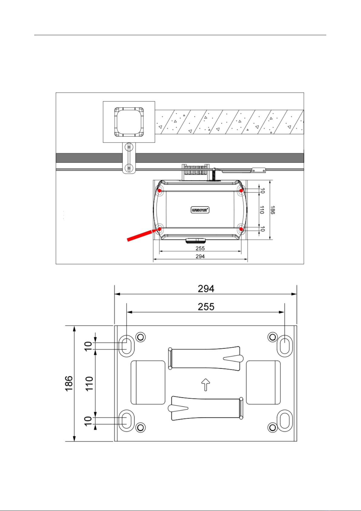
Step 5 - Fitting Mounting Plate and Motor...................................................................................8
Step 6 - Motor Position Adjustment.............................................................................................9
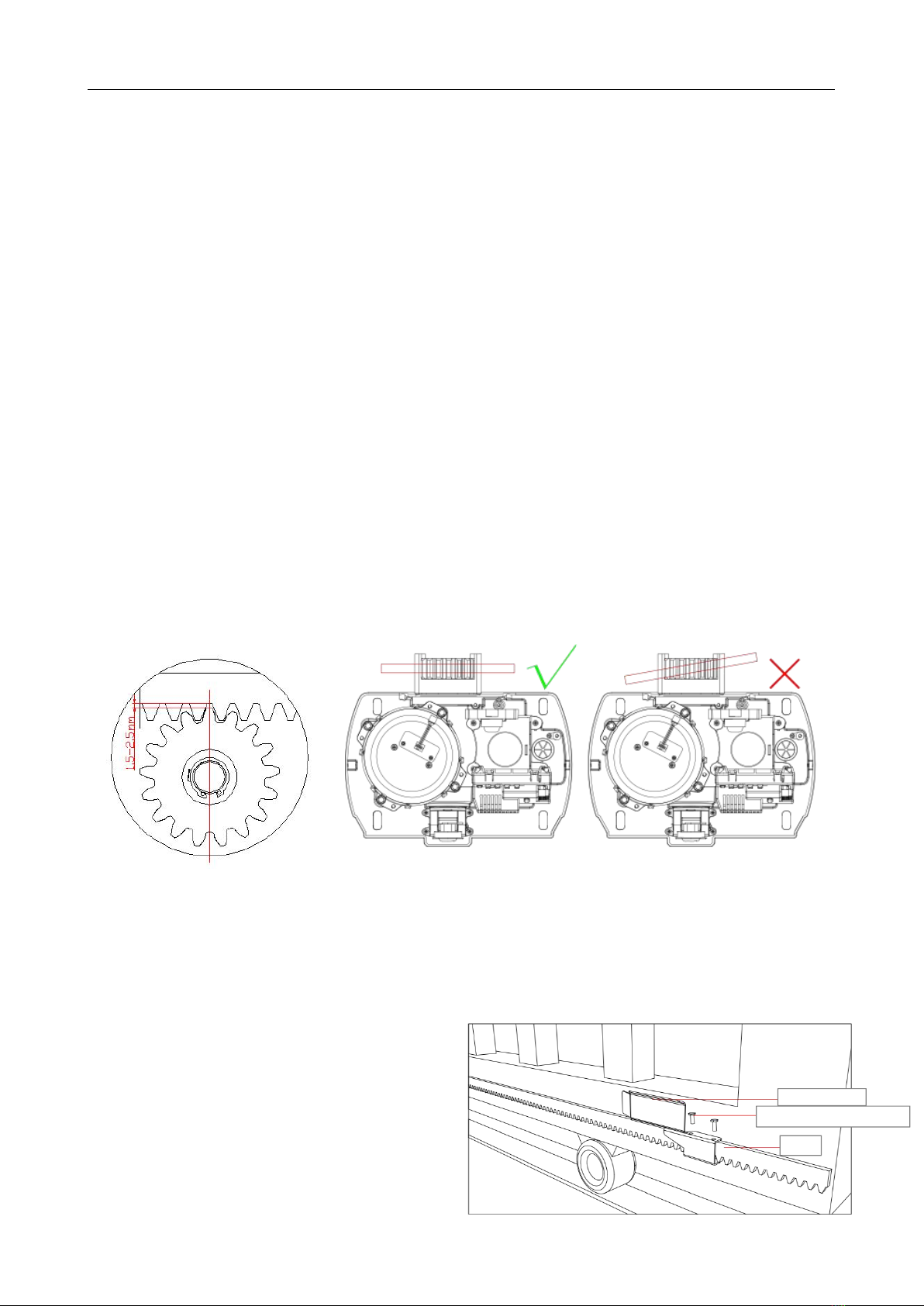
Step 7 - Gear Rack & Motor Alignment.......................................................................................9
Step 8 - Limit Switch Stops.......................................................................................................10
Step 9 - Powering on.................................................................................................................13
Step 10 - Testing Travel and Limit Stops...................................................................................14
Control Board.................................................................................................................................15
Programming and Wiring..........................................................................................................15
DIP Switch Adjustment..............................................................................................................16
Potentiometer Adjustment.........................................................................................................17
Terminal Instructions.................................................................................................................18
Wiring to the Terminal................................................................................................................19
Connecting Infrared Photocells.................................................................................................20
Remote Control Learning and Clearing.....................................................................................21
Maintenance...................................................................................................................................26
Troubleshooting.............................................................................................................................26

GA600AC Sliding Gate Opener User Manual
1
Then the gate will move in
the set direction.
Default Setting Instruction
The gate opener will open the gate to the right-hand side as its default setting. By default, the
opener mounts on the right-hand side. (Figure 1)
Figure 1
Gate in closed position Gate in open position
Before installation: Test the gate opener by plugging it into a power source and pressing the
remote. Press the opening button, the output gear rotates, then press the stop button, the output
gear stops rotating. Finally, press the closing button, the output gear rotates to the opposite
direction. This will give you an understanding of the way in which the opener will move the gate.
Figure 2
Note: Ensure that the gate opener is unplugged before proceeding with installation. Please
keep fingers away from the motor output gear whilst it is turning.
If your gate needs to open from the other direction (to the left, refer to Figure 3), your opener needs
to be mounted on the left-hand side as shown, the relative wires need to be swapped over, please
check under “Terminal Instructions” for swapping. (Factory default setting is for right-hand opening:
opener mounted on the right-hand side).
Figure 3
Any works done to the gate opener must be completed whilst the power is off, and the
opener is unplugged.
Press the first/top button
on the remote.
Rotating output gear will
drive the gate frame.

GA600AC Sliding Gate Opener User Manual
2
Parts List
Parts List (standard configuration)
No.
Picture
Name
Quantity
Note
1
Motor
1
2
Mounting Plate
1
3
Expansion Bolt M10×120
4
4
Manual Release Keys
2
5
Remote Control
2
6
Spring Limit Switch
Accessories Box/
Magnetic Limit Switch
Accessories Box
1
6-1-1
Spring Limit Switch Bracket
1
For use
when
installing
spring
switch
limit.
Spring Stop Mounting
Screw M6X10
4
6-1-2
Magnet Bracket
2
For use
when
installing
magnet
switch
limit
Magnets(S/N)
2
Magnetic Limit Switch Stop
Mounting Screws M6X18
4
Nuts M8
4
Flat Washers φ8
2

GA600AC Sliding Gate Opener User Manual
3
No.
Picture
Name
Quantity
Note
Spring Washers φ8
2
6-2
Nuts M10
4
6-3
Flat Washers φ10
8
6-4
Spring Washers φ10
8
6-5
Hexagon Head Bolt
M10×35
4
Note: Extra flat washers and spring washers are spare parts.
Parts List (optional)
No.
Picture
Name
Quantity
1
Galvanized Gear Rack
1m/pc
2
Nylon Gear Rack
1m/pc
3
Infrared Photocell
1 set
4
Wireless Keypad
1
5
Alarm Lamp
1
6
WIFI Adapter
1 set
Additional remote controls: Spare/Additional remotes for the automatic gate kit, these will need to
be paired to the motor.
Infrared photocell: Detects pedestrians, vehicles and objects that cross an infrared beam and
prevents the gate from closing.
Wireless keypad: Allows secure access through the gate used with a user set code.
Wired control: Allow users to control the opening and closing of the door through an external
push-button.
Alarm lamp: Alerts people near the gate and users that the gate is in operation.

GA600AC Sliding Gate Opener User Manual
4
Technical Parameters
Model
GA1000AC
Power Supply
110VAC/60Hz; 220VAC/50Hz
Motor Power
300W
Gate Moving Speed
12m/min
Maximum Loading Weight
1000KG
Remote Control Distance
≥30m
Remote Control Mode
Single button mode / Three button mode
Limit Switch
Spring limit switch / Magnetic limit switch
Working Noise
≤56dB
Working Duty
S2, 20min
Recording of up Remote Controls
25
Remote Frequency
433.92 MHz
Working Temperature
-20°C - +70°C
Overlook Size
293x247x300mm
Package Weight
16KGS
Installation
Before You Start
·GA1000AC Sliding Gate Automation Kit is suitable for powering the opening and closing motion
of gates up to 1000kg in weight, up to a length of 12m.
·Gate motion is achieved by the rotating output gear of the gate opener driving the gear rack
(sold separately) fitted to the moving gate.
·The gate opener requires you to press the remote control once to open, and once again to
close. This is a safety feature to ensure safe operation.
·The opener must be fitted within private property, never externally to a property’s boundary.
Any works done to the gate opener must be completed whilst the power is off and the
opener is unplugged. Any modifications/alterations/works to AC power components must
only be completed by a licensed electrician.
Tools Required
·Tape measure
·Level
·12mm concrete drill and hammer (when uses expansion screws)
·Phillips head screwdriver
·Straight screwdriver

GA600AC Sliding Gate Opener User Manual
5
Example Sliding Gate
Gate Track and Track Wheel Gate End Catch Gate Guide Rollers Gate Stop
Figure 4
Please ensure that the gate opener power cable is not plugged in at any stage before Step 9.
Step 1 - Gate Preparation
·Ensure that the sliding gate is correctly installed.
·The gate is horizontal and level and the gate can glide back and forth smoothly when moved by
hand before installing the gate opener.
·Wheels and guide rollers should rotate easily and be free from dirt or grime.
·Track should be flat, level and firmly affixed.
·Any misalignment in the gate will affect performance of the automatic gate opener.
Figure 5
The gate should slide smoothly by hand before attempting to install the gate opener.

GA600AC Sliding Gate Opener User Manual
6
Step 2 - Checking Manual Release
·Insert the key and open the manual release bar to enable the motor get into manual mode and
check that the motor output gear rotates freely by hand (Figure 6).
Figure 6
Step 3 - Removing / Installing Motor Cover
·Unscrew the two cover screws located at each side of the motor cover.
·Remove the rubber grommet below the limit switch (Figure 7).
Figure 7
Please Note: the rubber grommet must be fitted back onto the motor cover once the
cover has been re-fitted/replaced onto the base of the motor.
To make the motor into manual mode,
remove the slide cover, insert the key and
open the manual release bar.
In manual mode, the gear can turn freely
and the gate can be operated by hand.

GA600AC Sliding Gate Opener User Manual
7
Step 4 - Motor Pad Footing
·The motor pad concrete footing requires an area of no less than 450mm long x300mm wide
and a minimum depth of 200mm (Standard requirement).
·Ensure surface is level and parallel to the driveway.
Figure 8
Mounting Plate Dimensions
Use pencil, chalk or similar
tools to mark at the corners
of mounting plate

GA600AC Sliding Gate Opener User Manual
8
Step 5 - Fitting Mounting Plate and Motor
·Place the mounting plate and pre-fix it, tighten the nuts making sure to add spring and flat
washers (see Figure 9).
·Pre-position the machine according to (Figure 10) to ensure that the machine output gears and
racks are aligned and that the gears and racks are centered as far as possible (see Figure 11).
Tighten the expansion bolts and nuts on the mounting plate (ground screws are available).
·Secure the motor to the mounting plate by pre-tightening the bolts using M10x35 mm bolts with
spring and flat washers.
Figure 9
Figure 10

GA600AC Sliding Gate Opener User Manual
9
Step 6 - Motor Position Adjustment
·Place the motor and mounting plate on the concrete base.
·After placing, the motor can be fine-tuned back and forth, and tighten the fixing bolts after putting it
in the right position.
Step 7 - Gear Rack & Motor Alignment
·Ensure that the output gear has a minimum clearance of 1.5-2.5mm along the entire length of
gear rack fitted to the gate (as per Figure 11).
·Ensure output gear and gear rack are correctly aligned. Under no circumstances should the gate
opener output gear carry any weight of the gate. It is the task of the gate castors or wheels to
carry the weight of the gate.
·If the gate doesn’t slide freely by hand, adjust the height of the gear rack accordingly until the full
length of gate slides freely by hand.
Figure 11
Step 8 - Limit Switch Stops
A. Spring Limit Switch(6-1-1Accessories)
Included in your gate opener kit are two limit
switch stops which must be fitted to the gear
racks on your gate to ensure safe operation.
Limit switch stop mounting screws
Gear rack
Limit switch stop

GA600AC Sliding Gate Opener User Manual
10
The limit switch stops are designed to set the desired opening and closing position of your gate.
These limit switch stops are designed to come into contact with the spring/magnetic limit switch.
It is extremely dangerous that without or incorrect installation of the limit switch stops can cause
crash of gate, damage of internal structure of the motor, moreover, the gate may slide off the guide
rail.
Setting the Limit Switch Stops
Closed Position
·Position gate 150-200mm back from
the gate end catch closed position. This
will help in making sure you do not slam
the gate into the end stop/catch when
setting the closed position under power.
·Fit limit switch stop onto the top of
gear rack at the point where it meets the Spring limit switch on the motor.
·Tighten locking screws of limit switch stop.
Open Position
·Position gate 150-200mm back
from the gate stop open position.
This will help in making sure you do
not slam the gate into the end
stop/catch when setting the open
position under power.
·Fit limit switch stop onto the top of gear rack at the point where it meets the Spring limit switch
on the motor.
·Tighten locking screws of limit switch stop.
Test the spring limit switch stops by moving the gate manually until you hear a click, making sure
contact is made with the spring limit switch on the motor.
Spring limit switch
Spring limit switch

GA600AC Sliding Gate Opener User Manual
11
The installation of spring limit switch stops is shown in figure above.
B. Magnetic Limit Switch(6-1-2Accessories)
Included in your gate opener kit are two magnet limit switch stops with two different polarities: stop
in black color(N), stop in blue color(S). Before installing the magnet bracket, please fix the magnet
on the magnet bracket, and then install the magnet bracket on the proper position of the door gear
bar (refer to Figure 12).
To change the gate opener from right-hand
installed to left-hand installed, you should only
set it on the control board, no need to switch
over the two magnet limit switch stops. So it’s
extremely important to decide the limit switch
stops position and make sure the polarities are 100% correct.
Installation drawing of limit switch stop polarities for right-hand and left-hand:
Figure 12
The magnet holder is mounted as shown
磁钢
Blue magnet (S)
Black magnet (N)
Black magnet (N)
Blue magnet (S)
Open Position Limit Switch Stop
Closed Position Limit Switch Stop
Gear Rack
Magnet
Magnet bracket

GA600AC Sliding Gate Opener User Manual
12
Setting the Limit Switch Stops
Closed Position
·Position gate 150-200mm back from
the magnet bracket closed position. This
will help in making sure you do not slam
the gate into the end stop/catch when
setting the closed position under power.
·Fit magnet bracket onto the top of gear
rack at the point where it meets the Magnetic limit switch on the motor.
·Tighten locking screws of limit switch stop.
Open Position
·Position gate 150-200mm back from
the magnet bracket open position. This
will help in making sure you do not slam
the gate into the end stop/catch when
setting the open position under power.
·Fit magnet bracket onto the top of
gear rack at the point where it meets the Magnetic limit switch on the motor.
·Tighten locking screws of limit switch stop.
Test the magnetic limit switch stops by moving the gate manually until you hear a click, making sure
contact is made with the magnetic limit switch on the motor.
To Reset: Turning the power off will reset the limit switch stop memory. Power on the gate
opener again, pressing remote control or external push button switch to open and then
close the gate once, then new limit switch stop setting is completed.
Magnetic limit switch

GA600AC Sliding Gate Opener User Manual
13
Step 9 - Powering on
·Ensure that the outer cover has been fitted and fastened back onto the motor base.
·Before powering up the gate opener make sure the gate can travel by hand in manual mode
(key unlocked).
·Slide the gate to between the middle of the posts, approximately (see below diagrams).
·Lock the manual release spanner (key locked) in readiness for automatic mode.
·Plug the power cord into an approved RCD protected weatherproof outlet.
·Remote controls included in this kit are factory paired ready for use.
Figure 13
Please note: Warning signs
provided must be displayed
facing the street side.

GA600AC Sliding Gate Opener User Manual
14
Step 10 - Testing Travel and Limit Stops
Testing the Closed Position
·Ensure gate opener is installed as per step 5, 6 and 7 and the sliding gate is in the middle
position.
·Press remote (remotes included in kit are factory paired to the motor). The sliding gate will
begin to close.
·The limit switch stop will hit the limit switch and the sliding gate will stop.
·When the gate stops, measure the distance remaining between the sliding gate and the desired
closed position.
·You have now determined the closed position of the sliding gate when the limit switch stop hits
the limit switch.
·Adjust the limit switch stop from the measurement you have taken to get your final gate closed
position. The ideal closed final position for the gate frame is 10-15mm from closed gate end
catch.
Testing the Open Position
·Press remote, the sliding gate will begin to open.
·The limit switch stop will hit the limit switch and the sliding gate will stop.
·When the gate stops, measure the distance remaining between the sliding gate and the desired
open position.
·You have now determined the open position of the sliding gate when the limit switch stop hits
the limit switch
·Adjust the limit switch stops from the measurement you have taken to get your final gate open
position. The ideal open final position for the gate frame is 10-15mm from the gate stop.
Now the basic open and closed positions are set, for further setting functions and adjusting
parameters, please refer to pages 15-22 in this manual.

GA600AC Sliding Gate Opener User Manual
15
J5 Terminal
Hall Sensor
J3 Terminal
Learn Button
J6 Terminal
Dip Switches
Potentiometers
Control Board
Programming and Wiring
Any works to the 110V/220V AC must only be performed by a licensed electrician.
Ensure power is off before any modifications are made.
Figure 14
Fuse
(10A 250V fuse)
J2 Terminal
J1 Terminal
J4 Terminal

GA600AC Sliding Gate Opener User Manual
16
DIP Switch Adjustment
All changes to these settings must be completed by a licensed electrician.
Figure 15
Number
Function
Description
1
Slow Start Function
OFF-enable; ON-disable.
Default OFF
2
Limit Mode Switching
OFF-normally open limit; ON-normally closed limit.
Default ON, used with motor limit status, not
recommended to be modified by the user
3
Automatic Close Time
Automatic close time setting: the gate is operated to
open by remote control operation and will close
automatically after a few seconds delay.
3 OFF 4 ON: automatic close delay time is 12s.
3 ON 4 OFF: automatic close delay time is 24s.
3 ON 4 ON: automatic close delay time is 36s.
3 OFF 4 OFF: no automatic close function.
Default setting: 3 OFF 4 OFF
Disable the automatic close function.
4
5
Auto-reverse
Function
OFF-enable
ON-disable
Default position is OFF, this should align with the
opener status and is not recommended to be
modified by the users.
6
Remote Channel
OFF - Single channel
ON - Three channels

GA600AC Sliding Gate Opener User Manual
17
Potentiometer Adjustment
All changes to these settings must be completed by a licensed electrician.
Figure 16
VR1: Stall Force Mode
Maximum = More Force = Less sensitive
Minimum = Less Force = More sensitive
When Stall Force Mode is enabled (Dip switch 5 is at OFF position), the gate opener will
detect obstacles and impacts to the gate. If this is during opening, the gate will stop, if this is
during closing the gate will stop, and then re-open. Rotate VR1 clockwise to increase the
stall force, anti-clockwise to decrease.
For safety, we strongly recommend that Stall Force Mode is left enabled (Dip switch
5 is at the OFF position). Do not turn Dip switch 5 to the ON position.
VR2: Brake Force Adjustment
For adjusting brake force at the limit position during gate opening and closing. This should
only be adjusted for heavy gates that need additional force to brake when limit switch is
detected.
Rotate VR2 clockwise to increase, counter-clockwise to decrease. Default setting is at
minimum.
VR3: Slow Stop Width Adjustment
This switch controls how many seconds the gate opener operates at maximum speed.
Rotate VR3 clockwise to increase, rotate counter-clockwise to reduce.
When VR3 switches to minimum, slow start/stop function is disable.
VR4: Motor Output Force Adjustment
For best performance, set the torque at the lowest setting for secure use.
Rotate clockwise to increase, counter-clockwise to decrease.
Default setting is at maximum.
Table of contents
Other GATEXPERT Gate Opener manuals

GATEXPERT
GATEXPERT PY1200AC User manual

GATEXPERT
GATEXPERT GA500DC User manual

GATEXPERT
GATEXPERT DKC500DCL User manual

GATEXPERT
GATEXPERT GT1000DC User manual

GATEXPERT
GATEXPERT DKC500ACL User manual

GATEXPERT
GATEXPERT PY300DC User manual

GATEXPERT
GATEXPERT INDUS-E Series User manual

GATEXPERT
GATEXPERT PY300DCL User manual

GATEXPERT
GATEXPERT GT1000DCL User manual

GATEXPERT
GATEXPERT GK Series User manual