Gazelle Orange C330 HMB User manual

User manual


Congratulations on your
new Gazelle bike!
With your new Gazelle, you are assured of thousands of miles of
relaxed and carefree cycling pleasure. Your comfort and safety have
been at the forefront for Gazelle, ever since the first bicycle Gazelle
manufactured back in 1892. Gazelle was the first cycle brand in the
Netherlands to have been awarded the ISO 9001-2000 certificate
for its quality systems.
Your Gazelle bike has of course been designed and manufactured
with the greatest possible care, using high-grade and durable
materials. Accordingly, Gazelle oers you a long warranty. You will
find our warranty terms and conditions in the Safety & Warranty
manual (see www.gazellebikes.co.uk/service-and-warranty/
manuals).
In order to be able to derive optimum enjoyment from your new
bike, it is important to maintain it properly and have it checked
regularly by your Gazelle specialist. In this booklet you will read
how best to do this, and how you can carry out any minor repairs
yourself. You will also find all the information you need to set up you
bike exactly in line with your needs and wishes.
We therefore advise you to read through this user manual
attentively and keep it safely. Your Gazelle specialist is always ready
to advise and assist you.
We wish you many miles of cycling enjoyment!
Royal Dutch Gazelle

Table of contents
General information
. Handlebar
. Adjustment
. Maintenance
. Safety & repairs
. Handlebar grips
. Front fork & head tube suspension
. S e t - u p
. Maintenance
. Lighting
. Controls
. Repairs
. Brakes
. Adjustment
. Maintenance and repairs
. Gears
. Internal hub gear adjustment
. Internal hub gear maintenance
. Derailleur gear controls
. Derailleur gear adjustment
. Derailleur gear maintenance
. Chain and belt drive
. Adjustment: chain tension
. Maintenance
. Repairs
. Belt drive adjustment
. Belt drive maintenance
. Chain case
. Bottom bracket, cranks and pedals
. Maintenance
. Repairs
. Bike stand
. W heels
. Adjustment
. Repairs
. Removing a wheel
. Tyres
. Maintenance
. Repairs
. Saddle
. Frame
. E-bikes
. Child seats
. Transporting your bike by car
. Accessories
. Theft prevention
. Component designations
. Tables
. Tightening torques
. Distance travelled per
revolution
. NuVinci gear range
. Contact details
Finally
Disclaimer

General information
It is advisable to have your bike checked regularly by
your Gazelle specialist. We advise having the first service
carried out on your bike around six weeks and no later
than three months after starting to use it. Thereafter, it is
desirable to take the bike to your Gazelle specialist once
a year for a routine service. This will cover aspects such
as ensuring spoke tension is still correct and checking
whether there is any play in the hubs, the bottom bracket
or the headset.
If you detect any play while riding your bike you are best
going straight to your Gazelle specialist. If you carry on
cycling too long with defects, this can only make the
problems worse and ultimately cause damage. By having
your bike adjusted and checked on a regular basis you will
avoid expensive repair charges.
We do of course accept that you might like to look after
maintenance and minor repairs yourself. This user manual
explains how to maintain, adjust and repair your bike.
If you can’t manage it yourself or are in doubt as to the
correct procedures, please make your way to your Gazelle
specialist. Maintenance, repairs or adjustments carried out
incorrectly can result in defects.

NB
• Bolts, screws and nuts must be tightened to the
specified torques. Overtightening them can lead to
cracks and failures! You will find a listing of all specified
tightening torques in chapter 21, table 1.
• NEVER use a pressure washer to clean your bike. If you
do so, it can force grease and/or oil out of components
which could result in corrosion or serious damage.
• A particular type of bike will not be suitable for every
type of terrain. Bikes are not intended for extreme
loads such as those encountered when jumping or
riding over steps. Trekking bikes can be used on
paved roads and in trac. They are also suitable for
use gentle terrain, such as o-road cycle trails. Urban,
touring and children’s bikes can be used in trac and
on paved roads. Neither the manufacturer nor the
Gazelle specialist can be held liable for improper use
of the bike, especially a failure to comply with safety
guidelines, and any loss or damage arising from such
use.
• Take care to ensure that loose clothing, scarves, laces,
etc., do not get trapped in moving parts such as spokes
or pedals.
• Like any mechanical system, a bike is subject to
wear and tear. Wear and tear can aect the various
components in dierent ways. More intensive use will
shorten the lifespan of certain components.
• It is advisable to use a bike helmet for added safety.
Observe the national rules and standards for use of
helmets in all cases.
• Always comply with local and national trac rules
which apply in the country where you will be using the
bike.

1. Handlebar
. Adjustment
The height of the handlebar determines the pressure on
your hands and your back posture, among other things,
and therefore has a substantial impact on your ride comfort.
Gazelle bikes are fitted with dierent types of handlebars.
Of course they are all height-adjustable.
NB
• If you adjust the handlebar height, take care to ensure
that the MAX safety marking on the stem is not visible
(see fig. 1). If it is visible, it means that the handlebar
is set too high. With the Switch stem, the steerer tube
needs to extend at least to the min/insert mark.
• Avoid accidents, do not adjust the stem while riding!
Switch and Switch SL
The Switch stem height can be adjusted in two ways: by
tilting the handlebar, or by raising the stem itself.
Do you want to adjust your stem height? On the regular
Switch (figs. 2 to 3), you unscrew bolt (C) using a 6 mm
Allen key. This bolt is exposed when you lift the lever. To
adjust the height of the Switch SL (fig. 4) stem, you unscrew
bolts (D) using a 5 mm Allen key. You can now adjust the
stem. Once you have done so, tighten bolts (D) again.
The easier method is using the tilt system: you don’t need
any tools for this. First, pull the safety slide (fig. 2, A) on
top of the handlebar downwards. Then pull the entire lever
(fig. 3, B) upwards. You can now tilt the handlebar to the
desired height. The handlebar will be locked as soon as
you push the lever back down again.
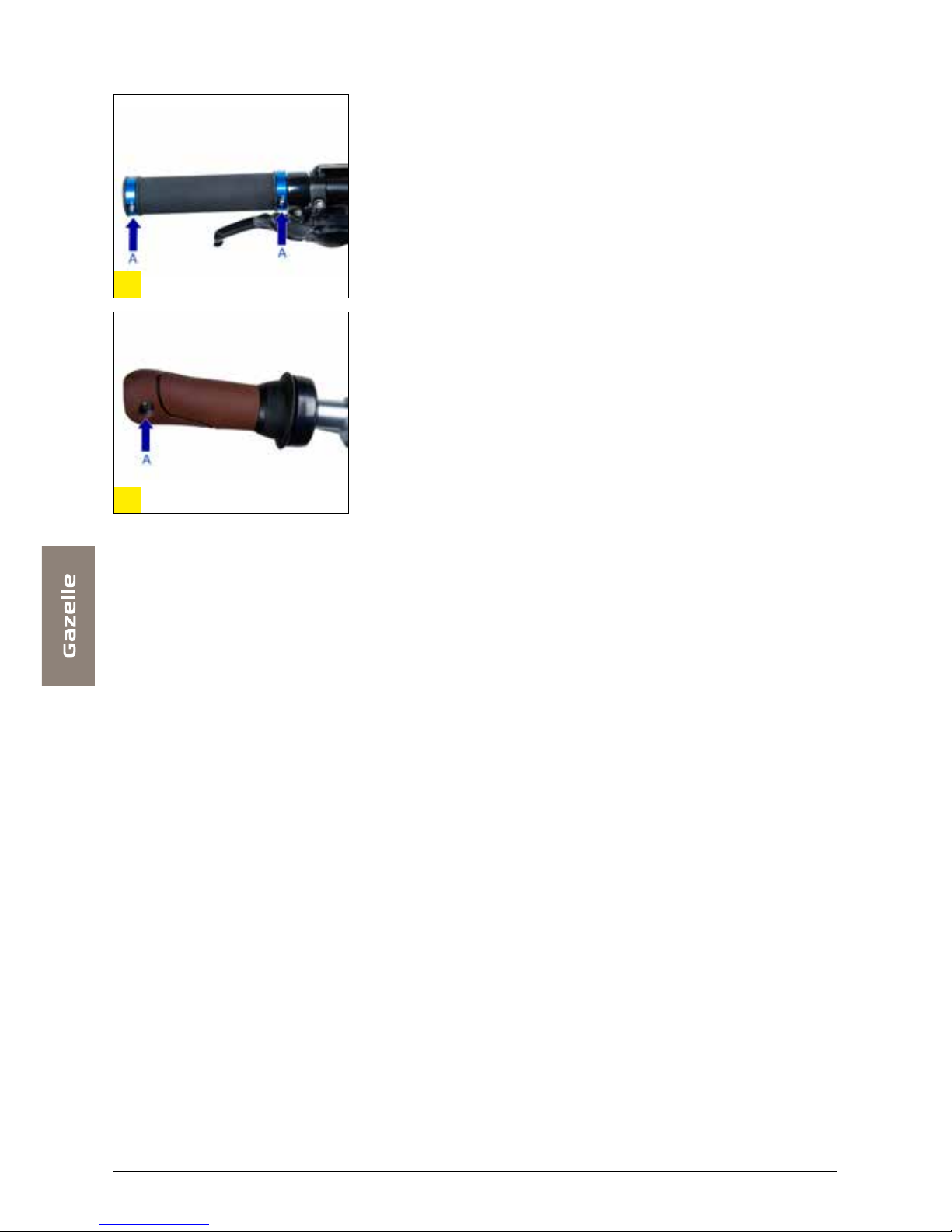
Magix and Smica (adjustable)
With Magix and Smica stems (see fig. 5) the stem is
clamped directly onto the steerer tube (this tube is the
upper part of the front fork). You adjust the handlebar
height by means of bolts (A). Unscrewing bolt (B) enables
the angle of the front assembly and hence the handlebar
height to be adjusted.
Finally, you can tilt the handlebar tube itself. You can do
this by unscrewing bolt (C). If you have a Smica stem, you

can unscrew the bolts using a 5 mm Allen key; you will
need a 6 mm key for the Magix.
Shuttle and New Shuttle
In order to adjust the height of the Shuttle or New Shuttle
stem (see fig. 6), you need to remove the cap from the
stem first. You can then twist the front assembly so as to
expose bolt (A). You can unscrew it with a long Allen key
(6 mm), whereupon you can adjust the handlebar to the
desired height. Re-tighten the bolt firmly once you have
finished. You adjust the position of the front assembly with
bolt (B) and the handlebar tube with bolt (C). You need to
use a 6 mm Allen key for this as well.
CQS-JM3358-2 stem
You can adjust the height of the stem using the bolt (fig. 7,
A) at the top of it. You unscrew bolt (B) to adjust the front
assembly. If you want to tilt the handlebar itself, you do so
using bolt (C). You need to use a 6 mm Allen key for all the
bolts.
Fixed stem
To adjust the height of the stem itself, you unscrew bolt (A)
by a couple of turns using a 6 mm Allen key (see figs. 8
and 9). You will then need to give it the bolt couple of taps
with a (rubber) hammer. You will now be able to set the
handlebar to the desired height by turning it back and forth.
Re-tighten the bolt firmly once you have finished. You can
adjust the position of the handlebar tube using clamping
bolt (B).
Head lock
Various Gazelle models feature a head lock. This prevents
the handlebar from swinging right round. You activate the
head lock by twisting the black ring counterclockwise (see
fig. 10). The arrows and the padlock icons on the aluminium
ring indicate the direction of rotation. You will see a red
strip when the head is locked. Should you accidentally set
o with the head still locked, you will still be able to turn the
handlebar to avoid any accidents. You will hear a ratcheting
sound, intended to draw your attention to the fact that the
head lock is still engaged. You release the head lock by
twisting the black ring clockwise, after which the bike can
be steered normally.

. Maintenance
The handlebar stem and the headset require lubrication
every so often. If you notice that steering is sti, creaks or
does not operate correctly in some other way, then it may
need lubrication. You can go to your Gazelle specialist for
this.
. Safety & repairs
After a long period of use, the headset may get a little
loose. If this is the case you will need to visit your Gazelle
specialist, who has the knowledge and tools available
to remedy the problem at once. Should you be unlucky
enough to have a fall and bend or damage the handlebar
as a result, it must be replaced. Attempting to bend the
handlebar back into shape may cause it to break. Deep
scratches in aluminium handlebars risk developing into
fractures. This also requires the handlebar to be replaced.

2. Handlebar grips
To prevent handlebar grips from working loose, Gazelle
has developed handlebar grips that can be secured with a
small bolt (see figs. 11 and 12).
If you would like to rotate your grips a little around the
handlebars you will need to unscrew bolt (A) slightly first
using a 4 mm Allen key. Once you have set it to the desired
position, you need to secure the handlebar grip again by
tightening the small bolt.

3. Front fork & head tube
suspension
Some Gazelle bikes are fitted with a suspension front fork.
There are two types of suspension: front fork suspension
and internal headset suspension. You can read how to
set up both of them here. With front fork suspension, the
suspension mechanism is located in the front fork legs; if
you have internal headset suspension, then the suspension
mechanism is built into the steerer tube.
. S e t - u p
Front fork suspension
You set the stiness of the front fork suspension with
the thumbwheel (fig. 13, A) on the front fork. You turn it
clockwise to make the suspension stier, anticlockwise
to make it softer. Take care to ensure that the tension is
the same both sides. If necessary, you can achieve this by
zeroing both sides. If you then see to it that you adjust both
sides by the same number of turns, you will be sure that the
tension is equal in both suspension units.
Internal headset suspension
You set suspension stiness by means of the small bolt
under the head tube, between the two legs of the fork (see
fig. 15). You turn it clockwise to make the suspension stier;
to make it softer you turn it anticlockwise. Whenever you
want to adjust the internal headset suspension, you will
need to slide the rubber sleeve down in order to expose
the adjustments system (see fig. 14). Unscrew nuts (A) with
a 14 mm open-ended spanner. Tighten the 4 screws (B)
using a 6 mm Allen key to remove any play. Tighten each
opposite pair of screws (B) together. Repeat until all play
has been eliminated. If, by any chance, the screws (B) are a
little too tight, unscrew them alternately so as to eliminate
excessive friction. Ensure the 4 screws (B) are tightened
evenly. The fork is adjusted correctly if there is no play
while the fork is still able to move smoothly. Tighten all nuts
(A) to prevent the bolts from coming loose. Refit the rubber
sleeve to seal o the fork.

Now check the fork movement. If it is in order, vertical
movement will be smooth and there will be no lateral or
fore and aft play. If one of these criteria is not met, repeat
the entire process as often as necessary in order to
achieve smooth movement without play.
. Maintenance
Dirt and moisture can get into the mechanism as it moves
up and down, thus reducing its eectiveness. That is why
the suspension needs to be cleaned regularly, under
the rubber gaiters as well. The suspension is best kept
clean using a moistened soft brush. After cleaning, the
suspension mechanism needs to be oiled with Teflon-
containing oil.
To lubricate the fork itself, it needs to be taken apart. This is
a specialist job! Accordingly, make your way to your Gazelle
specialist: he has the expertise required to carry out this
job in his workshop.

4. Lighting
As a cyclist, it is most important to be seen by other road
users in order to be able to negotiate trac safely. In this
chapter you will read all about the operation of the various
types of lighting you can come across on your Gazelle bike.
. Controls
Front light
Most front lights are powered by a hub dynamo. Only the
Trelock LS 330 and the Spanninga Swingo front lights are
battery-powered.
The Tung Lin is powered by a bottle dynamo: you need to
click it onto the tyre sidewall first.
Gazelle front lights are switched on via the on/o, slide or
rotary switch. See figures 16 to 24 for a summary of all front
lights and the location of the on/o switch. Pressing switch
(A) once switches the lighting on; press it again to switch
o the lighting completely. The Busch & Müller front light
(fig. 25, see next page) does not have an on/o switch: you
operate it via the e-bike display.
AXA Blue Line
FenderVision
LightVision
Spanninga Smart Move Retro AXA Pico
Trelock LS Spanninga Swingo Thung Lin
Fenderlight

Do you have a Trelock LS 330 front light? Then your light
has three positions. Press once to switch the light on; press
twice for the flashing function and three times to switch it
o.
With most front lights, you can simply move the body to
direct the light beam. If you have a bike with the Gazelle
FenderVision front light, then you can alter the position of
the front light and hence the light beam using the black
slider on the left-hand side. You will see two bulbs in the
Tung Lin front light: the second one is a spare.
Rear lighting
The latest generation of Gazelle rear lights has been
designed to last a long time. The LED lights consume
very little power and have a very long lifespan. The use
of batteries to power rear lights has consigned wiring
problems to history. You switch the rear lighting on using
the button (A) (figs. 26 to 33). If you have a Herrmans,
SlimVision or AXA Ri rear light, then you have three
positions: on, auto and o:
On: use this to have the light on all the time.
This can be useful for instance in misty weather when it is
Busch&Muller Lumotec IQ Cyo
Hermans/Racktime
Gazelle LED XB & Gazelle nr.
AXA Spark
Gazelle SoloVision
BE Vision & SlimVision
AXA Ri
Spanninga Brasa
Spanninga O-GUARD

desirable to have a rear light on, whilst it is still too light to
switch on the automatic function.
Auto: in this position, the rear light switches on
automatically as soon as it gets dark and the bike starts
moving. When you stop again, for instance at a trac light
or at the end of your trip, then the rear light will stay on for
another minute (sidelight function).
O: use this to switch the light o completely all the time.
This is useful when you carry the bike on your car: in these
conditions it is not desirable to switch on the light as it
could be a nuisance to other road users.
You choose the setting by the number of times you press
the sliding button (once for on, twice for auto, three times
for o). On the Herrmans rear light you will see a yellow
LED light up on the reflector when you have switched it to
the auto setting.
The other rear lights (Spanning Brasa, Gazelle BE Vision,
Axa Spark and Gazelle No. 7) only have an on and o
setting, operated using the button (A). Do you have a
Spanning Brasa light? This light has an indicator on it. Once
the remaining charge in your batteries is down to 6 hours
(or less), the indicator will turn red.
. Repairs
Front lighting
Should the lighting fail to work, then the problem is likely
to be in the wiring. It could be a broken cable, or the
connections may have worked loose. Start by checking the
dynamo connection: is the cable connected properly to
the dynamo? Check the connection of the cable to the light
next. If both connections appear to be sound, it is likely to
be a broken cable, in which case the cable will need to be
replaced. You can make your way to your Gazelle specialist
for this.
Do you have a Trelock LS 330 or Spanninga Swingo front
light? If so, it is likely that you will need to replace the
battery. If you have a Trelock LS 330 front light (see figs. 34
and 35) the procedure is as follows: press (B) in and slide
Trelock LS
Trelock LS

the light out of its holder. Underneath the detached light
you will find a red button (C); slide this button forward. This
allows you to slide the cover of the light o and replace the
batteries.
Do you have a Spanninga Swingo front light (see figs. 36
and 37)? To replace the battery, you will need to prise the
lens o the light using a coin in the indentation (B).
If the LED lighting still fails to light up even though the
cables and/or batteries are in order, then the fault can lie
in the electronics. It may also be the case that the bulb has
blown. You Gazelle specialist can check this out for you
and replace the defective components as necessary.
Rear light
Rear lights on Gazelle bikes are fitted with LED bulbs with a
very long lifespan. However, if your light is not working, it is
likely to be the batteries that are due for replacement.
On the Herrmans, Spanninga Brasa, SlimVision, BE Vision,
Gazelle LED XB, Gazelle No. 7 and Solo Vision rear lights,
you need to remove the screws (B) (see figs. 38 to 47).
You can then remove the cover or slide, after which you
can replace the batteries. NB: on the Solo Vision and the
Spanninga Swingo
Spanninga Swingo
BE Vision & SlimVision
BE Vision & SlimVision Spanninga Brasa
Spanninga Brasa
Hermans/Racktime
Herrmans integrated into
carrier

AXA Ri, the screw is located behind the on-o sliding
button: the screw is visible when the light is switched o.
If you have an AXA Spark or Spanninga O-GUARD rear
light (see figs. 48 to 51), then you can remove the cover
using a coin in the indentation (B) (AXA) or at the on-o
button (Spanninga).
Always ensure you fit the batteries with the orientation
shown in the rear light. Also be sure to use Alkaline
batteries exclusively since they don’t leak, thus precluding
damage.
If your rear light with the new batteries fails to light up, it is
likely that the battery contacts have become dirty. Please
refer to your Gazelle specialist if this is not the case.
Spanninga O-GUARD
AXA Spark
Gazelle SoloVision
Gazelle SoloVision
Spanninga O-GUARD
AXA Ri AXA Spark
Gazelle LED XB & Gazelle nr.

5. Brakes
Brakes are of crucial importance for your safety. This
chapter will tell you all you need to know about adjusting
and maintaining your brakes. Do you have hand-operated
brakes? If so, the left-hand lever operates the rear brake
and the right-hand lever operates the front brake.
NB
• Do you have a bike with front suspension? If you brake
hard, then the front suspension will cause fore-and-aft
rocking which can be hazardous in bends. This eect
is mitigated by using both front and rear brakes. This
means you should never brake with the front brake on
its own!
• Your brakes have a longer stopping distance in wet
weather, be sure to allow for this!
. Adjustment
If you feel the brake lever pulling all the way without
applying the brakes fully, then you will need to tension the
cable using the adjusting screw (fig. 52, A) on the brake
lever mount on the handlebar. Unscrew the adjusting screw
by a couple of turns. Next, tighten the lock nut against the
brake lever mount so the adjusting screw cannot work
loose while riding the bike. Take care to ensure that the
indentation on the adjusting screw is facing downwards,
otherwise it can fill up with rainwater.
Do you want to adjust the position of the brake levers
relative to the handlebar grips? Use the adjusting bolt (fig.
52, B) to change the position of the brake lever.
. Maintenance and repairs
Do your brakes work less well in the winter? It could be that
your brake cables have frozen solid. If this is the case, your
cables will need to be re-lubricated. This is a specialist job:
we would advise you to go to your Gazelle specialist for
this.

V-brake
The V-brake system is relatively simple: you brake by
means of the brake blocks, which press against the
wheel rim when the brakes are applied. If you notice your
V-brakes losing braking power, it could mean that your
brake blocks are worn out. Check the brake blocks for
wear by looking to see whether the grooves are still visible
on them. If the blocks are worn down to the bottom of the
grooves (to around half a millimetre) then they must be
replaced.
To replace the brake blocks, you need to release cable
(A) above the brake first (see fig. 53). Unscrew bolt (B)
next, using a 5 mm Allen key. You can now remove the
brake blocks and replace them with new ones. Take care
to ensure you fit the correct type of brake block! If you buy
the wrong kind of brake block, you could damage the rim.
Make sure you fit the left-hand brake block on the left-hand
side and the right-hand one on the right-hand side.
After replacing them, check the gap between the brake
blocks and the rim. If this is excessive, you will have
insucient braking power; if it is too small, they can rub
against the rim. Use an ideal gap of 2 mm as your starting
point. If the gap is greater than this, you can reduce it using
the adjusting screw (A) on the brake lever (see fig. 52).
Ensure the front end of the brake blocks is slightly closer to
the rim than the rear, otherwise the brakes will squeal.
V-brakes can cause the rims to wear. This eect is
accelerated by contamination such as sand or street grime.
Accordingly, clean your brakes frequently, using water or a
brush, for instance, and have your rims checked regularly
by your Gazelle specialist as to whether they are still stable
or need replacing.
NB
V-brakes are very powerful. Do not therefore use the
front brake on its own, always use the front and rear
brakes together! Some Gazelle V-brakes are equipped
with a power modulator to apply the braking power more
gradually. This prevents the brakes from being applied
too abruptly, producing a short delay before full braking
power is applied.

Drum brakes
A drum brake is fitted in the hub of the wheel. The brake
system consists of a brake drum that rotates with the
wheel; inside the drum there are two brake shoes which
do not rotate with the wheel. When you brake, the brake
shoes are forced against the drum: this brings the wheel to
a standstill. Drum brakes wear out with the passage of time.
You will become aware of this when the brake levers are
almost able to touch the handlebars. All it usually requires
is to adjust the brakes. Push the lever (A) upwards (see
fig. 54). Then screw the nut (B) in to the point where the
brake just catches, then unscrew it just a touch so it is just
clear and the wheel spins freely. Apply the brakes firmly at
regular intervals while you are adjusting them. Take care
to ensure that the brake cable or pin is located correctly in
the lever so it doesn’t fly out!
Next lift the bike up and spin the wheel. If the wheel keeps
on spinning without sticking, then you have adjusted the
brake correctly, otherwise the wheel will stop abruptly. In
the latter case you will need to back the nut o again by
one or more turns.
The same procedure can be followed if you have rod-
operated brakes. You just need to ensure you adjust the
front brake first before starting on the rear.
Brake shoe replacement should be left to the Gazelle
specialist when required. He is the only one who can
determine the type of brake shoe that needs to be used.
Roller brake
The Shimano roller brake (see fig. 55) is a type of drum
brake. Correct adjustment is achieved by twisting the
barrel adjusters at the hub (A) and at the brake lever on the
handlebar (see chapter 5.1, fig. 52). The roller brake also
has a grease fitting (B) to add grease to lubricate the brake.
We would advise you to go to your specialist for this. If you
top up the brake incorrectly or use the wrong lubricant, you
can actually cause serious damage to the brake! If you still
want to lubricate the brake yourself, bear in mind that you
must only use Shimano roller brake grease.
This manual suits for next models
1
Table of contents
Other Gazelle Bicycle manuals

Gazelle
Gazelle Innergy Series User manual

Gazelle
Gazelle Innergy Series User manual

Gazelle
Gazelle Easyflow HMS User manual

Gazelle
Gazelle Innergy Series User manual

Gazelle
Gazelle bike User manual

Gazelle
Gazelle Easy Glider User manual

Gazelle
Gazelle Cabby User manual

Gazelle
Gazelle Makki Series User manual

Gazelle
Gazelle E6100 User manual

Gazelle
Gazelle Orange Pure Innergy User manual