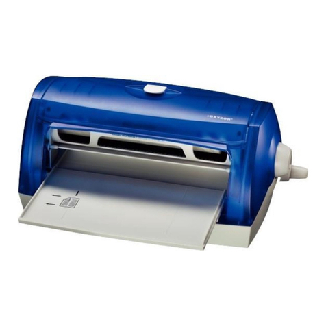
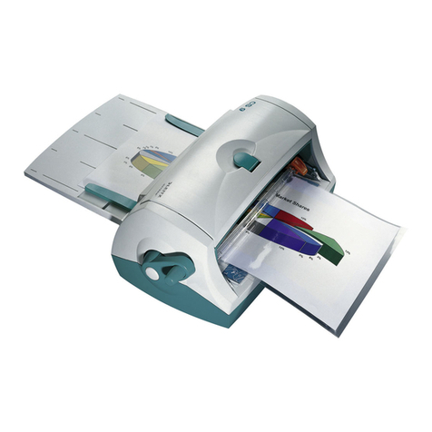
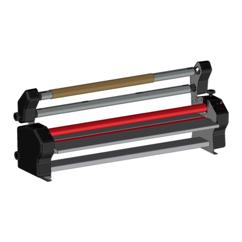
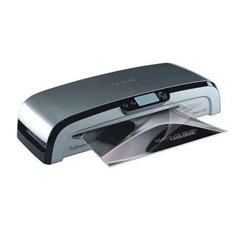
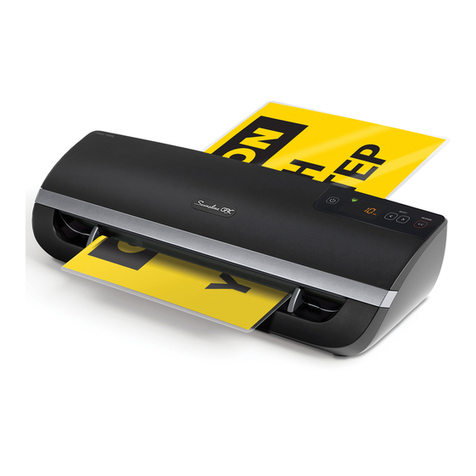
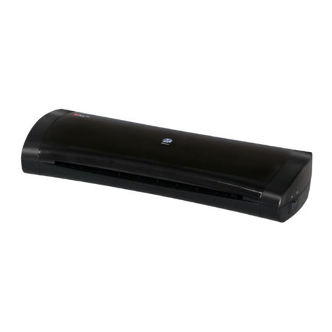
GBC Ultima 65 User manual

Ultima 65 Laminator
INSTALLATION & OPERATION MANUAL
Document Number: CBT10000 Rev A
Do not duplicate without written
permission
from ACCO
Brands

ACCO Brands reserves the right to make changes to this publication and to the products described in it without
notice. All specifications and information concerning products are subject to change without notice. Reference
in this publication to information or products protected by copyright or patent does not convey any license
under the rights of ACCO Brands or others assumes no liability arising from infringements of patents or any
other rights of third parties.
This publication is copyrighted © 2016 by ACCO Brands. All rights reserved.

1. Safety
YOUR SAFETY, AS WELL AS THE SAFETY OF OTHERS IS
IMPORTANT TO GBC. IN THIS INSTRUCTION
MANUAL AND ON THE PRODUCT ARE IMPORTANT
SAFETY MESSAGES. BEFORE YOU INSTALL OR USE
THE MACHINE, READ AND FOLLOW ALL THE SAFETY
NOTICES CAREFULLY IN THIS CHAPTER.
Observe all the safety information provided.
Observe all safety warnings. Never remove safety
warnings or other information from the equipment.
Read all of the instructions and save these
instructions for further use.
The safety alert symbol precedes each safety
notice in this manual. The symbol indicates a
potential personal safety hazard to you or others, as
well as cause product damage or property damage.
This safety alert symbol indicates a potential
electrical shock. It warns you not to open the paper
cutter and expose yourself to hazardous voltage.
THE FOLLOWING WARNINGS ARE FOUND ON THE
ULTIMA 65 LAMINATOR.
This means you can be seariously hurt or killed if you
open the product and expose yourself to hazardous
voltage.
Do not open. No user servicable parts insides. Refer
servicing to qualitfied service personal.
This safety message means that you could be burned
and your fingers or hands could be trapped and
crushed in the hot rollers. Clothing, jewelry long hair
could be caught in the rollers and pull you into
them.
This safety notice means you can cut yourself if
not careful operating the trimmer.
WARNING: Do not attempt to service or
repair the laminator.
WARNING: do not connect the laminator
to an electrical supply or attempt to operate the
laminator until you have completely read these
instructions. Maintain these instructions in a
convenient location for future reference.
General safeguards
•Use this laminator only for its intended
purposes as according to the
specifications outlined in the operating
instructions.
•Keep hands, long hair, loose clothing and
articles such as necklaces or ties away
from the front of the rollers to avoid
entanglement and entrapment.
•Avoid contact with the rollers during
operation or shortly after the laminator
has been turned off. The rollers can
reach temperatures in excess of 300ºF.
•Keep hands and fingers away from the
path of the sharp film cutter blade
located at the film exit.
Do not place the laminator on an
unstable cart, stand or table. An
unstable surface may cause the
laminator to fall resulting in serious
bodily injury. Avoid quick stops,
excessive force and uneven floor
surfaces when moving the laminator on
a cart or stand.
•Do not defeat or remove electrical and
mechanical safety equipment such as
interlocks, shields and guards.

•Do not insert objects unsuitable for
lamination.
•Do not expose laminator to liquids.
Electrical Safeguards
•This laminator must be connected to a supply
voltage corresponding to the electrical rating
as indicated on the serial plate located on the
rear of the machine.
•Unplug the laminator before moving it, or
when it is not in use for an extended period
of time.
•Do not operate the laminator with a damaged
power supply cord or plug.
•Do not overload electrical outlets as this can
result in fire or shock.
•Do not alter the attachment plug. This plug is
configured for the appropriate electrical
supply.
•The unit is intended for indoor use only.
CAUTION: The receptacle must be
located near the equipment and easily
accessible. Do not use an extension cord.
•Disconnect the attachment plug from the
receptacle to which it is connected and keep
the power supply cord in your possession
while moving the laminator.
•Do not operate the laminator with a damaged
power supply cord or attachment plug, upon
occurrence of a malfunction, or after
laminator has been damaged. Contact an
authorized GBC service representative for
assistance.
GBC Technical Service
To order replacement accessories, service, parts, or an
Equipment Maintenance Agreement, please contact
GBC Technical Service and Support at:
United States
ACCO Brands GBC Technical Service and Support
4 Corporate Drive Lake Zurich, IL 60047-8997
www.gbcconnect.com
1-800-723-4000
Canada
Ontario and Quebec –1-800-268-3310
All other Provinces –1-800-268-3447
Local 905-595-3100
Callcentre@GBCCanada.com
Mexico
(55) 1500 5778
Lada SIN costo: 01 800 759 6825

2. Warranty
Limited 90 Day Labor Warranty; USA, Mexico, and
Canada
ACCO Brands USA LLC, ACCO Brands, 4 Corporate
Drive, Lake Zurich, IL 60047 (in Mexico, ACCO Brands
Mexicana,Neptuno 43, Fraccionamiento Nueva
Industrial Vallejo México 07700 D.F. México), (in
Canada, ACCO Brands Canada Inc., 7381 Bramalea
Road, Mississauga ON L5S1C4) (each, respectively,
“ACCO Brands”) warrants to the original purchaser
that this ACCO Brands product is free from defects in
workmanship and material under normal use and
service for a period of: ninety (90) days for parts and
labor after purchase.
ACCO Brands’ obligation under this warranty is limited
to replacement or repair, at ACCO Brands’ option, of
any warranted part found defective by ACCO Brands
without charge for material or labor. Any replacement,
at ACCO Brands’ option, may be the same product or a
substantially similar product that may contain
remanufactured or refurbished parts. This warranty
shall be void in the following circumstances:
(i) if the product has been improperly installed or
misused,
(ii) if the product has been damaged by negligence or
accident, or
(iii) if the product has been altered by anyone other
than ACCO Brands or ACCO Brands’ authorized agents.
Without limiting the generality of the previous
paragraph, ACCO Brands’ obligation under this limited
warranty does not include:
(iiii) damage caused to the rollers by knives, razors, or
other sharp tools; by any foreign objects falling into
the working area of the laminator; or by cleaning the
laminator with solutions or materials that harm its
surfaces;
For warranty execution, please contact ACCO Brands
at: 800-723-4000 or www.gbcconnect.com in the USA
800-263-1063 or www.gbccanada.com in Canada (55)
1500 5578 or www.accomexico.mx in Mexico
TO THE EXTENT ALLOWED BY APPLICABLE LAW,
THIS WARRANTY IS IN LIEU OF ALL OTHER
EXPRESSED WARRANTIES. REPRESENTATIONS OR
PROMISES INCONSISTENT WITH OR IN ADDITION
TO THIS WARRANTY ARE UNAUTHORIZED AND
SHALL NOT BE BINDING ON ACCO BRANDS. TO
THE EXTENT PERMITTED BY APPLICABLE LAWS,
ANY IMPLIED WARRANTIES (IF APPLICABLE) ARE
LIMITED IN DURATION TO THE DURATION OF
THIS WARRANTY. SOME STATES AND
JURISDICTIONS DO NOT ALLOW LIMITATIONS ON
HOW LONG AN IMPLIED WARRANTY LASTS, SO
THE ABOVE LIMITATION MAY NOT APPLY TO
YOU. TO THE EXTENT PERMITTED BY APPLICABLE
LAW, IN NO EVENT SHALL ACCO BRANDS BE
LIABLE FOR ANY SPECIAL, INCIDENTAL, PUNITIVE,
EXEMPLARY, CONSEQUENTIAL OR SIMILAR
DAMAGES, WHETHER OR NOT FORESEEABLE.
SOME STATES AND JURISDICTIONS DO NOT
ALLOW THE EXCLUSION OR LIMITATION OF
SPECIAL, INCIDENTAL, PUNITIVE, EXEMPLARY,
CONSEQUENTIAL, OR SIMILAR DAMAGES, SO THE
ABOVE EXCLUSION OR LIMITATION MAY NOT
APPLY TO YOU.
FOR CONSUMERS WHO HAVE THE BENEFIT OF
CONSUMER PROTECTION LAWS OR
REGULATIONS IN THEIR JURISDICTION OF
PURCHASE OR, IF DIFFERENT, IN THEIR
JURISDICTION OF RESIDENCE, THE BENEFITS
CONFERRED BY THIS WARRANTY ARE IN
ADDITION TO ALL RIGHTS AND REMEDIES
CONVEYED BY SUCH CONSUMER PROTECTION
LAWS AND REGULATIONS.
To the extent permitted by law, this warranty is
not transferable and will automatically terminate
if the original product purchaser sells or
otherwise disposes of the product.
This warranty gives you specific legal rights. Other
rights, which vary from jurisdiction to jurisdiction,
may exist. In addition some jurisdictions do not
allow (i) the exclusion of certain warranties, (ii)
limitations on how long an implied warranty lasts
and/or (iii) the exclusion or limitation of certain
types of costs and/ or damages, so the above
limitations may not apply.

3. Specifications
Model
Ultima 65
Operating Speed
Variable
Speed 1 - 10
2 ~ 10 ft./min.
Warm-up Time
< 10 Minutes
Maximum Film Width
27”
Maximum Film Roll Diameter
5”
Film Supplies Supported:
Film Thickness
EZ Load Films
Standard 1” Core Films
Nap I Films
1.5mil / 3mil (38mic / 75mic)
Yes
Yes
Dimensions:
Width
Height
Depth
Weight
Machine: Shipping:
35” (88.9cm) 41.25” (104.8cm)
14” (35.6cm) 18.00” (45.7cm)
21” (53.3cm) 26.25” (66.7cm)
111lbs (50.3kgs) 116 lbs (52.6kgs)
Electrical Requirements
•
Voltage
•
Receptacle
Electrical Requirements
•
120V, 60Hz
•
NEMA 5-15R
Height
Figure 1. Ultima 65 Dimensions

FCC Class B Notice
This device complies with Part 15 of the FCC Rules.
Operation is subject to the following two conditions:
This device may not cause harmful
interference.
This device must accept any interference
received, including interference that may
cause undesired operation.
NOTE: This equipment has been tested and found
to comply with the limits for a Class B digital device,
pursuant to Part 15 of the FCC Rules. These limits
are designed to provide reasonable protection
against harmful interference in a residential
installation. This equipment generates, uses, and
can radiate radio frequency energy and, if not
installed and used in accordance with the
instructions, may cause harmful interference to
radio communications. However, there is no
guarantee that interference will not occur in a
particular installation. If this equipment does cause
harmful interference to radio or television reception,
which can be determined by turning the equipment
off and on, the user is encouraged to try to correct
the interference by one or more of the following
measures:
- Reorient or relocate the receiving antenna.
- Increase the separation between the
equipment and receiver.
- Connect the equipment into an outlet on a
circuit different from that to which the
receiver is connected.
- Consult the dealer or an experienced
radio/TV technician for help.
Canada Class B Notice - Avis
Canada, Class B
This Class B digital apparatus complies with
Canadian ICES-003.
Cet appareil numérique de la classe B est conforme
à la norme NMB-003 du Canada.
Modifications
Any modifications made to this device that are
not approved by ACCO Brands may void the
authority granted to the user by the FCC and/or
by Industry Canada to operate this
e
q
u
ip
m
e
n
t
.
Toutes modifications apportées à ce dispositif
et non approuvées par ACCO Brands annuleront le
droit accordé à l’utilisateur par le FCC et/ou par
Industrie Canada de faire fonctionner cet
équipement.
Disposal
At the end of its useful life, your product is
considered to be Waste Electrical and Electronic
Equipment (WEEE). As such, it is important to note
that:
WEEE is not to be disposed of as unsorted
municipal waste. It is to be collected
separately such that it can be disassembled
so its components and materials can be
recycled, re-used, and recovered (burned
for energy content in electricity
production).
Public collection points have been set up by
municipalities for the collection of WEEE,
free of charge to you.
Please return your WEEE to the collection
facility nearest your home or office.
If you have difficulty locating a collection
facility, the retailer that sold you the
product should accept your WEEE.
If you are no longer in contact with your
retailer, please contact ACCO for assistance
with this matter.
Recycling of WEEE is geared toward
protecting the environment, protecting
human health, preserving raw materials,
improving sustainable development, and
ensuring a better supply of commodities in
the European Union. This will be achieved
by retrieving valuable secondary raw
materials and reducing the disposal of
waste. You can contribute to the success of
these goals by returning your WEEE to a
collection facility.
Your product is marked with the WEEE
symbol (wheelie bin with an X through it).
This symbol is to inform you that WEEE is
not to be disposed of as unsorted municipal
waste.

4. Installation
Service
WARNING:
Do not attempt to service or repair
the laminator.
Failure
to observe this warning could
result in
severe
personal injury or death.
Disconnect the plug from the receptacle and contact
GBC Technical Service when one or more of the
following has o
cc
urr
e
d
.
•
The
power supply cord or attachment plug is
damaged.
•Liquid has been spilled into the laminator.
•The laminator is m
a
l
f
un
c
t
i
o
nin
g
after being
mishandled.
•The laminator does not operate as described in
these ins
tr
u
c
t
i
o
ns.
Installation
•Shipping damage should be brought to the
immediate attention of the delivering carrier.
•Place the laminator on a stable flat surface
capable of supporting 150 lbs.
•The surface should be at least 30” high to
assure comfortable positioning during
operation. All four rubber feet should be on the
supporting surface.
•Connect power cord to an appropriate power
source. Avoid connecting other equipment to
the same branch circuit to which the laminator
is connected as this may cause nuisance
tripping of the circuit breaker or blown fuses.
•The laminator should be positioned to allow
exiting film to drop freely to the floor.
Accumulation of laminate as it exits the
laminator may cause film to wrap around the
rollers, causing a jammed condition.
•Avoid placing laminator near sources of heat or
cold. Avoid locating the laminator in the direct
path of forced, heated or cooled air.
Caring for Ultima 65
The only maintenance required by the operator is to
periodically clean the rollers. Keeping the rollers clean
ensures that your finished items will not be damaged by
dirt and adhesive build-ups.
CAUTION: the following procedure is performed
while the laminator is hot. Use extreme caution.
WARNING: Do not apply cleaning fluids or
solvents to the rollers.
WARNING: Do not attempt to laminate
adhesives marked ‘Flammable’.
WARNING: Do not expose laminator to liquids.
1. Remove the film from the laminator following the
procedure outlined in the section FILM LOADING
AND THREADING.
2. Clean the top and bottom rollers with a clean,
damp lint-free cloth. If there are any adhesive
build-ups, you may use isopropyl alcohol instead of
water.
3. To remove difficult debris Preheat the laminator
until the READY LAMP () illuminates.
4. Push and hold the SLOW Backward button to
rotate the upper and lower rollers with the safety
shield open.
5. Follow the procedure in section FILM LOADING
AND THREADING, Method Using Film Threading
Card to reload the laminator.
Note: Do not use metal scouring pads to clean the heat
rollers!
Note: Covering machine when not in use will reduce
dust build-up on the rollers and film which can lead to
poor lamination quality.
WARNING: Do not laminate glitter and/or
metallic items. Damage to the rollers may result.
The side covers and feed table can be cleaned with a
lint-free cloth and a mild detergent.

5. Feature Guide
Figure 1
Figure 2
A. MAIN POWER SWITCH: Located at the back of the
machine, applies power to the laminator. The ‘ON’
position is indicated by the ‘I‘symbol. The ‘OFF’
position marked ‘O’ symbol (figure 2).
Figure 3
B. CONTROL PANEL:
a. FOOTAGE COUNTER –Tracks the number of feet
used since last reset. To reset the footage counter
press the RESET button.
b. ON/OFF BUTTON –used to put the machine in
Standby mode or wake the machine up from
Standby mode.
i. READY –Machine is ready to use when
machine beeps and the Icon LED turns
GREEN.
ii. WARM-UP –Machine is warming up when
the Icon LED is AMBER.
iii. STANDBY –When icon is illuminated
AMBER, machine is in Standby mode.
Press the ON/OFF button to wake the
machine and warm-up to operational
temperature.
c. FILM SELECTION –(1.5 OR 3 MIL) –Press the
film selection button to toggle between 1.5 and
3 mil films
d. SPEED CONTROL –Controls the speed of the
laminator when the run button is pushed.
i. AUTOSPEED –Machines runs at optimum
speed for the film type selected. PUSH the
speed dial to turn this feature ON/OFF.
GREEN LED will illuminate when ON.
ii. MANUAL SETTINGS 1 THRU 10 –Operator
can manually select the speed 1 –10. The
speed will increase as you adjust from 1 to
10. AUTOSPEED must be turned OFF to
manually adjust speeds.
e. RUN –Push the RUN button to run the
laminator in the forward direction.
f. SLOW FORWARD/REVERSE –Press and Hold to
run the machine slowly in Forward or Reverse.
Using SLOW Speed will allow the machine to
run even when Heat Shield is open.
g. STOP –Used to Stop the laminator. There are
two stop buttons one on front panel and one
on back of the machine.
Figure 4
C. HEAT SHIELD: (figure 4) Prevents inadvertent
contact with the heat rollers. The HEAT SHIELD
must be lowered for the RUN operation to work.
D. FEED TABLE: (figure 4) The Feed Table is used to
position items for lamination. Feed table must be
closed and latched for laminator to operate.

Figure 5
E. FEED TABLE LATCHES: (figure 5) Used to unlock and
lock the FEED TABLE.
F. FEED TABLE GUIDE: (figure 5) Aligns items as they
are being fed into the laminator. Especially helpful
on longer items to reduce skew. The guide can be
moved by loosening the knob and sliding the guide
to the desired position and then tightening the
knob.
Figure 6
G. HEATED NIP ROLLERS: (figure 6) Heats the film to
activate the adhesive and provides pressure to
ensure film adheres to the media.
.
H. IDLER BARS: (figure 6) The Idler Bars, located near
each supply roll, are used to direct the film to the
NIP ROLLERS. The lower Idler Bar is attached to the
Feed Table to facilitate easy film loading.
I. PULL ROLLERS: The Pull Rollers are located at the
back of the laminator. They simultaneously pull the
film through the laminator and provide tension as
the film cools to ensure quality lamination.
Figure 7
J. REAR SLITTER: (figure 7) Used to cut the film when
it exits the rear of the laminator.
K. FUSE: (figure 2) The Fuse is an electrical safety
device, located under the main power switch.
L. AUTO SHUT-OFF: After two hours of inactivity the
laminator will shut down. To activate the laminator,
ensure the Main Power button is in the ON position
(‘I‘) and press the ON/OFF button on the front of
the machine.
Figure 8
M. FILM ROLL SUPPLY: The Ultima 65 can use both EZ
Load and Standard roll laminating film (figure 8).
Figure 9
N. FILM SADDLES: Film supply is loaded into the
saddles (figure 9).
O. FILM SHAFT: The Film Shaft is used for loading
standard film onto the Ultima 65 Laminator.
P. FILM SHAFT HOOKS: Located on the back of the
machine the shaft hooks are used to store the Film
Shaft when EZ load film is being used.

7. Operation
FILM LOADING
Figure 10
Figure 11
Figure 12
Figure 13
Figure 14
Figure 15
CAUTION: the following procedure is
performed while the laminator is hot. Use extreme
caution.
TIP: Film loading is easiest when machine is in a
Ready State or while warming up.
Step 1: Lift Safety Shield and lower feed table by
pushing down on table latches (Fig. 10)
Step 2: If reloading film, cut the remaining top and
bottom film webs between the supply rolls and the
idler bars (Fig 10)
Step 3: Raise the four film levers on the FILM
SADDLES and remove the old rolls of film. (Fig. 11)
Step 4: Install new film rolls (Fig 12)
a. EZLoad Film –Insert the film directly into the
film saddles, making sure the film end plugs
correspond with the saddles in color and size.
b. Standard Film –First the film needs to be
loaded on the film shaft and then the shaft
can be loaded into the film saddles. See
directions below for loading film on shaft.
Step 5: Close the four film holder levers on the
saddles.
Step 6: Thread the film (Reference Fig. 12 and 15)
a. Unwind top and bottom film rolls allowing
enough slack for threading.
b. Drape Lower supply roll (Role 1) over the
top idler bar allowing enough slack to close
the feed table.
c. Drape the film from Upper roll (2) over the
film from the lower roll.
d. Ensure top and bottom film edges are
aligned.
Step 7: Close the feed table and the Heat Shield.
Turn the top roller an extra ¼ turn to create slack in
the film off the top roller. (Fig 14)
Step 8: Using the film threading card included with
the film, push the film into the NIP of the Heat
Rollers. Continue to push the threading card while
the Forward button is hit in step 9. (Fig 14)
Step 9:
Using the Slow Forward button push and hold while
watching the film thread through the Heat & Pull
rollers and observe the film exiting the back of the
laminator.

Loading Standard Film on Film Shaft
Figures 16-19
1. With the feed table in the open position, rest the
roll of film on the idler bar and edge of the feed
table.
2. Remove the dark blue end cap off the Film Shaft
by pulling it off.
3. Ensure O-ring is set to proper film with position.
4. Insert the Film Shaft through the core in the roll
of film and replace the dark blue end cap. Ensure
the film is flush against the O-ring and that the
top and bottom rollers are aligned during
installation.
Note: When inserting the shaft review the film
loading diagram to ensure loading the film in the
proper direction for top and bottom rolls.
OPERATION
1. Move the Main Power switch to the ‘ON’ ( )
position (figure 1).
2. Ensure the proper film is selected.
3. When the laminator reaches operating
temperature, the green ready indicator () on
the control panel will illuminate.
4. Position the item(s) to be laminated on the feed
table.
5. Press the RUN button .
6. Slide the item(s) to be laminated into the Heat
Rollers.
7. When the laminated item(s) exit the rear of the
laminator, hit the Stop Button .
8. Use the Rear Slitter located at the back of the
laminator to separate the laminated item(s) from
the film web.
9. During use watch the film exit to ensure film is
not drawn back into exit to prevent film wraps.
Note: Continuously feeding similar size media in
the same location will create a wear spot. Mixing
up the feeding location will give heat rollers longer
life.
CLEARING A JAM
Film jams may occur if the laminator is not
positioned to allow exiting film to drop freely to
the floor. Accumulation of laminate as it exits the
laminator may cause film to wrap around the
roller, causing a jammed condition.
To clear a jam it is necessary to rotate the rollers in
a reverse direction.
1. Immediately stop the laminator by hitting the
Stop Button
2. Open the Heat Shield and the Feed Table
3. Cut the top and bottom film webs by the Idler
bars
4. Grasp the loose ends of the web and pull
straight out while pushing and holding the
Slow Reverse Button .
5. When the film has cleared the Heat Rollers
stop the laminator by letting go of the Slow
Reverse Button
6. Re-thread the film following the FILM
LOADING instructions earlier
Lamination Speed Guide
When using AutoSpeed the machine will operate
at speed setting 4 and adjust the speed of the
laminator automatically based on roller
temperature changes to ensure quality output.
Turn-off AutoSpeed by pressing the Speed Control
dial and manually set the speed based on the
reccomendations below.
Media Type
Speed
Thin (News Print)
4 - 6
Medium (Copy Paper)
3 - 5
Thick (Card Stock)
2 - 4
Heavy Stock (Poster Board)
1 - 2
Lamination Tips
Do not attempt to laminate abrasive or
metal items such as staples or paper clips as
they will damage the heat rollers.
Do not force items into the nip area of the
rollers. An item that is not easily drawn into
the laminator is probably too thick to
laminate.
Wrinkles may result if an attempt is made to

reposition an item once the rollers have
grasped it.
Do not stop the laminator before an item has
completely exited the rear of the laminator.
Even a momentary stop will cause a mark
(heat line) to appear on the laminated item.
Adhesive will be deposited on the Heat Rollers
if:
-Only one roll of film is used. The top
and bottom rolls must be used for
problem free lamination.
-One or both rolls of film are allowed to
run completely off the core.
-Top and bottom roll film edges are not
evenly aligned
TROUBLE SHOOTING
SYMPTON
POSSIBLE CAUSE
CORRECTIVE ACTION
Machine will not turn ON
The Main Power switch on the back is
not in the ‘ON’ ( I ) position.
Laminator is not connected to power
source
The Fuse has been blown
Move the main power switch to the ‘ON’ (
I ) position
Insert plug into appropriate receptacle
Reset the circuit breaker
Machine is ON but will not
run
Heat Shield or Feed Table are not fully
closed to activate safety switch
Ensure the Heat Shield and Feed table are
fully closed.
Machine rollers stop/stall
while laminating
Media is too thick
Look for film wrap around rollers
If possible use thinner media.
If film is wrapped around roller use
procedure outlined in Clearing a Jam.
Film Doesn’t Stick to Media
Machine not hot enough
Running to fast
Wrong Film Setting
Adhesives will not stick to select
Inks/Toners/Toner Oils/Coatings
Ensure ready light is on
Try slower speed setting
Confirm proper film thickness selected
If possible print document on another
printer
Film or Media appears cloudy,
milky or silvering (very small
dots typically seen in dark
areas)
Machine not hot enough
Running to fast
Wrong Film Setting
Adhesives will not stick to select
Inks/Toners/Toner Oils/Coatings
Machine can also be too hot
Ensure ready light is on
Try slower speed setting
Confirm proper film thickness selected
If possible print document on another
printer
If above does not resolve try letting the
machine cool
Long Ripples appear on the
Film and/or Media
Film is too hot when exiting the pull
rollers on the back of the machine.
Slow down the laminator
Common on longer lamination runs. Try
shorter runs or stop to let cool when
present
Waves on one side of the film
or media
The film is walking during lamination due
to uneven tension
Ensure all saddles are closed fully
Try swapping the top and bottom film rolls
Waves appear outward from
the trailing edge of media
(Boat Waking)
Will occur on thicker media
Use thinner media when possible
Slowing down will reduce amount of boat
waking
Appearance of small dimples
Machine is too hot
Ensure Ready light is on

on media and film (Orange
Peel)
Confirm proper film thickness selected
Allow machine to cool
Media and film have little
square patterns on the output
(Checker boarding)
Film is too hot when exiting the pull
rollers on the back of the machine.
Slow down the laminator
Common on longer lamination runs. Try
shorter runs or stop to let cool when
present
Gap/Air Pocket between the
edge of the media and the
film (Tenting)
Typically found when thicker media is
used
Try running slower
Ensure ready light is on and proper
temperature.
When possible use thinner media
Film has bubbles
Uneven tension across the width of the
film
Debris in film and/or on the media or
roller
Cut or divot in the heat roller silicone
Swap the top and bottom rolls
Wipe them down with a lint-free cloth
Use caution when slitting film for roll
changes or jams to prevents cuts into the
rollers.
Film curls opposite directions
on the edges as it exits the
back.
Film supplies not properly matched
during manufacturing process
Swap the top and bottom rolls
Media has curl when
lamination complete
Film rolls have too much tension or drag
on them.
Film Rolls have different amounts of
tension
Clean the film saddles with damp lint-free
cloth.
Film rolls should be approximately the
same size. Try swapping top and bottom
rolls to change the tension.
Wrinkles in film as the film
enters the Heat Rollers
Not enough tension on film rolls
Ensure the saddles are fully closed
Clean the saddles with lint-free cloth
Excessive Adhesive build up
on the Heat Roller edges
The Top and Bottom roller are not
aligned.
When using standard film make sure both
rolls are pressed up against the film
alignment O-ring on the shafts.
Other manuals for Ultima 65
4
Table of contents
Other GBC Laminator manuals

GBC
GBC 4120 User manual

GBC
GBC Ultima 65 User manual

GBC
GBC FUSION 6000L User manual

GBC
GBC Docuseal 2700 User manual

GBC
GBC F-36 Operating instructions

GBC
GBC Orca 1600 User manual

GBC
GBC FUSION 3100L Instruction Manual

GBC
GBC FUSION 1000L User manual

GBC
GBC FUSION 3000L User manual

GBC
GBC HeatSeal H65 User manual

GBC
GBC Discovery 50 User manual

GBC
GBC Inspire Plus A4 User manual

GBC
GBC 3500 PRO-SERIES User manual

GBC
GBC Titan 1244WF Installation instructions

GBC
GBC FUSION 5100L Instruction Manual

GBC
GBC H320 User manual

GBC
GBC VOYAGER User manual

GBC
GBC HeatSeal H65 User manual

GBC
GBC H320 User manual

GBC
GBC GBC A4 POLAR User manual