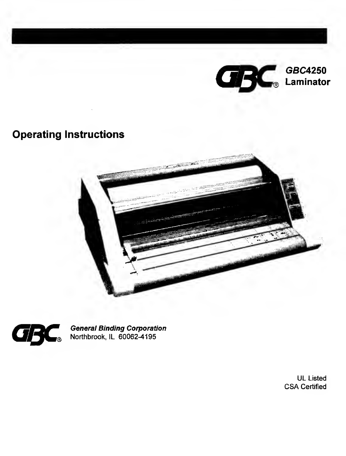
GBC GBC4250 User manual

Operating
Instructions
General
Binding
Corporation
Northbrook,
IL
60062^195

2
The
“Word
Finishing"
People
TABLE
OF
CONTENTS
SECTION
ease
•
IMPORTANT
SAFETY
INSTRUCTIONS
3
•
IMPORTANT
SAFEGUARDS
3
-GENERAL
3
-ELECTRICAL
4
-SERVICE
5
-SET-UP
5
•
SPECIFICATIONS
6
•
KNOW
YOUR
GBC4250
LAMINATOR
6
•
FILM
LOADING
&
THREADING
8
-METHOD
USING
FILM
THREADING
CARD
10
-METHOD
FOR
TACKING
NEW
FILM
TO
PRE-EXISTING
FILM
13
.
FILM
ALIGNMENT
PROCEDURE
15
•
FEED
TABLE
REMOVAL
15
•
OPERATING
PROCEDURE
15
•
SPEED
GUIDE
AND
THE
ART
OF
LAMINATION
17
•
FILM
TENSION
AND
ADJUSTMENT
19
•
CARING
FOR
THE
GBC4250
LAMINATOR
20
•
TROUBLE
SHOOTING
GUIDE
22
CLEARING
A
FILM
JAM
23

3
The
“Word
Finishing"
People
IMPORTANT
SAFETY
INSTRUCTIONS
YOUR
SAFETY
AS
WELL
AS
THE
SAFETY
OF
OTHERS
IS
IMPORTANT
TO
IMPORTANT
CAREFULLY.
IN
THIS
INSTRUCTION
AND
ON
THE
PRODUCT
ARE
SAFETY
MESSAGES.
READ
THESE
MESSAGES
^^THIS,
THE
SAFETY
ALERT
SYMBOL,
PRECEDES
EACH
SAFETY
MESSAGE
IN
THIS
INSTRUCTION
MANUAL.
THE
SYMBOL
INDICATES
A
POTENTIAL
PERSONAL
SAFETY
HAZARD
THAT
COULD
HURT
YOU
OR
OTHERS,
AS
WELL
AS
CAUSE
PRODUCT
OR
PROPERTY
DAMAGE.
Awarning
^
DO
NOT
ATTEMPT
TO
SERVICE
OR
REPAIR
THE
GBC4250
LAMINATOR
OTHER
THAN
AS
INSTRUCTED
IN
THESE
OPERATING
INSTRUCTIONS.
Awarning
DO
NOT
CONNECT
THE
GBC4250
LAMINATOR
TO
AN
ELECTRICAL
SUPPLY
OR
ATTEMPT
TO
OPERATE
THE
LAMINATOR
UNTIL
YOU
HAVE
COMPLETELY
READ
THESE
INSTRUCTIONS.
MAINTAIN
THESE
INSTRUCTIONS
IN
A
CONVENIENT
LOCATION
FOR
FUTURE
REFERENCE.
Awarning
TO
GUARD
AGAINST
INJURY,
THE
FOLLOWING
SAFETY
PRECAUTIONS
MUST
BE
OBSERVED
IN
THE
INSTALLATION
AND
USE
OF
THE
LAMINATOR.
A
IMPORTANT
SAFEGUARDS
GENERAL
Keep
hands,
long
hair,
loose
clothing
and
articles,
such
as
necklaces
or
ties,
away
from
the
front
(heat)
and
rear
(pull)
rollers
to
avoid
entanglement
and
entrapment.

The
“Word
Finishing”
People
The
heat
rollers
can
operate
at
temperatures
close
to
300
°F.
Avoid
contact
with
the
heat
rollers
during
operation
or
shortly
after
power
has
been
removed
from
the
laminator.
Keep
hands
and
fingers
away
from
the
path
of
the
sharp
film
cutter
blade
located
at
the
area
of
film
exit.
Do
not
use
the
laminator
for
other
than
its
intended
purpose.
Do
not
place
the
laminator
on
an
unstable
cart,
stand,
or
table.
An
unstable
surface
may
cause
the
laminator
to
fall
resulting
in
serious
bodily
injury.
Avoid
quick
stops,
excessive
force,
and
uneven
floor
surfaces
when
moving
the
laminator
on
a
cart
or
stand.
Do
not
defeat
or
remove
electrical
and
mechanical
safety
equipment
such
as
interlocks,
shields
and
guards.
Do
not
insert
objects
unsuitable
for
lamination
or
expose
the
equipment
to
liquids.
ELECTRICAL
The
laminator
should
be
connected
only
to
a
source
of
power
as
indicated
in
these
instructions
and
on
the
serial
plate
located
on
the
rear
of
the
laminator.
Contact
an
electrician
should
the
attachment
plug
provided
with
the
laminator
not
match
the
receptacles
at
your
location.
Disconnect
the
attachment
plug
from
the
receptacle
to
which
it
is
connected
and
maintain
the
power
supply
cord
in
your
possession
while
moving
the
laminator.
Disconnect
the
attachment
plug
from
the
receptacle
when
the
laminator
is
not
used
for
extended
periods
of
time.
Do
not
operate
the
laminator
with
a
damaged
power
supply
cord
or
attachment
plug,
upon
occurrence
of
a
malfunction,
or
after
the
laminator
has
been
damaged.
Contact
GBC’s
Technical
Service
Department
or
your
dealer/distributor
for
assistance.
Observe
the
marked
electrical
rating
on
the
equipment
to
avoid
overloading
the
branch
circuit
(receptacle)
to
which
the
laminator
is
connected.
Disconnect
the
attachment
plug
from
the
receptacle
and
maintain
the
power
supply
cord
in
your
possession
when
replacing
the
line
fuse.
The
fuse
holder

'®r/?e
“Word
Finishing"
People
is
located
on
the
rear
of
the
equipment.
Replace
fuse
only
with
type
specified
on
fuse
rating
label
located
near
fuse
holder.
SERVICE
Perform
only
the
routine
maintenance
referred
to
in
these
instructions.
Do
not
attempt
to
service
or
repair
the
laminator.
Contact
GBC’s
Technical
Service
department
or
your
dealer/distributor
for
service
or
repair.
Disconnect
the
attachment
plug
from
the
receptacle
and
contact
GBC’s
Technical
Service
Department
or
your
dealer/distributor
when
one
or
more
of
the
following
has
occurred:
-The
power
supply
cord
or
attachment
plug
is
damaged.
-Liquid
has
been
spilled
into
the
laminator.
-The
laminator
is
malfunctioning
after
being
mishandled.
-The
laminator
does
not
operate
as
described
in
these
instructions.
SET-UP
1.
Shipping
damage
should
be
brought
to
the
immediate
attention
of
the
delivering
carrier.
2.
Place
the
GBC4250
laminator
on
a
stable
flat
surface
capable
of
supporting
at
least
85
lb.
(39
Kg).
The
surface
should
be
at
least
30
inches
high
to
assure
comfortable
positioning
during
operation.
All
four
rubber
support
feet
of
the
laminator
shall
be
positioned
completely
on
the
supporting
surface.
This
supporting
surface
may
also
be
large
enough
to
place
the
material
which
is
to
be
laminated.
3.
The
laminator
should
be
located
to
allow
exiting
film
to
drop
freely
to
the
floor.
Accumulation
of
laminate
immediately
behind
the
laminator
as
it
exits
the
equipment
may
cause
the
film
to
wrap
around
the
rear
pull
rollers,
resulting
in
a
“jammed”
condition.
4.
Avoid
locating
the
laminator
near
sources
of
heat
or
cold.
Avoid
locating
the
laminator
in
the
direct
path
of
forced
heated
or
cooled
air.
5.
Connect
the
attachment
plug
provided
with
the
laminator
to
a
suitable
grounded
outlet
only.
Avoid
connecting
other
equipment
to
the
same
branch
circuit
to
which
the
laminator
is
connected
because
this
may
result
in
nuisance
tripping
of
circuit
breakers
and
blown
fuses.

The
“Word
Finishing"
People
SPECIFICATIONS
Operating
Speed-1.5
fpm
(45.6
cm)
to
10
fpm
(3
m)
Dimensions-
32.5
in.
(83
cm)
wide
x
21
in.
(53
cm)
long
x
12
(31
cm)
in.
high
Weight-
85
lb.
(39
kg)
Electrical
Requirements-
Refer
to
the
Serial
Plate
located
on
the
rear
of
the
laminator
for
the
specific
electrical
rating
applicable
to
the
provided
equipment.
Voltage
115V~.
60Hz
Current
12
A
Power
1450
W
KNOW
YOUR
GBC4250
LAMINATOR
A.
P
OWER
SWITCH:
Use
to
apply
power
to
the
laminator.
The
green
power
“ON”
lamp,
located
adjacent
to
the
power
switch,
will
illuminate
when
the
power
switch
is
set
at
the
"On”
position,
marked
I,
Set
the
power
switch
at
the
"Standby”
position,
marked
laminator
off.
B.
R
UN/STOP
SWITCH:
“Stop”
position
removes
power
from
the
Pull
Roller
drive
motor.
Moving
the
switch
to
the
“Run”
position
applies
power
to
the
drive
motor.
C.
SPEED
CONTROL:
Use
to
control
the
speed
of
lamination.
The
speed
is
adjustable
from
the
“Slow”
setting
of
1.5
fpm
(0.46
m)
to
a
“Fast”
setting
of
10
fpm
(3
m).
D.
“READY”
LAMP:
Continuously
illuminates
when
the
heat
rollers
are
sufficiently
hot
for
the
selected
speed
setting.
(!),
to
turn
the
CONTROL
PANEL
POWER
SMrrCK
RUN/STOP
SMTCH
•READV
LAMP

7
The
"Word
Finishing"
People
E.
“
WAIT”
LAMP:
Flashes
when
the
temperature
of
the
heat
rollers
is
insufficient
for
the
selected
speed
setting.
The
occurrence
of
a
flashing
wait
light
will
be
signified
by
an
audible
alarm
(beep).
F.
FEED
(SUPPORT)
TABLE:
The
Feed
Table
is
used
to
position
items
for
lamination.
The
laminator
will
operate
only
with
the
Feed
Table
and
Feed
Table
Latch
properly
installed.
G.
SAFETY
SHIELD:
Prevents
entanglement,
entrapment
and
inadvertent
contact
with
the
heat
rollers.
The
laminator
will
operate
only
when
the
Safety
Shield
is
located
in
the
full
down
position.
Power
to
the
laminator
is
removed
when
the
Safety
Shield
Is
lifted.
H.
TABLE
INTERLOCK
LATCH-
Used
to
lock
Feed
Table
into
position
and
activate
an
interlock.
The
interlock
latch
is
located
at
the
left
underside
of
the
feed
table.
The
table
cannot
be
removed
without
retracting
the
latch
to
the
right
while
lifting
the
table
upwards
and
away
from
the
laminator.
The
laminator
will
not
operate
when
the
feed
table
is
removed
and/or
the
Interlock
latch
is
retracted.
I.
FEED
GUIDE-
The
Feed
Guide
permits
aligning
the
item(s)
to
be
laminated.
Reposition
the
adjustable
feed
guide
by
loosening
the
knob
on
top
of
the
guide.
Slide
the
Feed
Guide
to
the
desired
position
and
tighten
the
knob
to
secure
the
Feed
Guide
in
place.
The
Feed
Guide
is
used
to
keep
longer
items
straight.
The
Feed
Guide
may
also
be
used
to
feed
small
items
side
by
side
by
positioning
the
feed
guide
towards
the
center
of
the
feed
table
and
placing
the
smaller
items
against
each
side
of
the
Feed
Guide
as
they
are
being
introduced
into
the
nip
point
of
the
heat
rollers.
J.
HEAT
ROLLERS-
Silicone
rubber
coated
aluminum
tubes.
Used
to
heat
the
laminating
film
and
compress
the
heated
film
to
the
items
being
laminated.
Heat
is
provided
by
an
internal
heating
element.
The
Safety
Shield
causes
the
rollers
to
separate
for
loading
new
film
or
close
once
the
laminating
film
is
loaded.
K.
IDLER
BAR-One
provided
for
each
film
supply
roll.
Used
to
direct
the
film
to
the
Heat
Rollers.
Bottom
Idler
Bar
is
removable
to
ease
film
loading.
FIGURE
2

8
The
‘Word
Finishing"
People
L.
P
ULL
ROLLERS-
The
set
of
rollers
located
at
the
back
of
the
laminator.
These
rollers
are
motor
driven.
They
are
used
to
simultaneously
pull
the
laminate
and
improve
the
quality
of
the
laminated
item.
M.
FILM
CUTTER:
Use
to
cut
the
film
web
at
the
area
at
which
the
web
exits
the
laminator.
N.
REVERSE
SWITCH:
Used
to
facilitate
removing
a
jammed
(wrap-
up)
condition.
The
pull
rollers
are
caused
to
rotate
in
the
reverse
direction.
The
laminating
film
is
pulled
back
into
the
laminator
when
the
Reverse
Switch
is
depressed.
O.
LINE
FUSE-
Located
in
the
fuse
holder
which
is
positioned
on
the
rear
of
the
equipment.
P.
CORE
CLIPS-
Mounted
on
the
Supply
Roll
Shaft.
Used
to
hold
the
film
roll
to
the
supply
roll
shaft.
Q.
FILM
WEB-
Laminating
film
loaded
into
the
equipment.
R.
NIP
POINT-
The
point
at
which
the
top
and
bottom
rollers
contact.
The
Nip
Point
of
the
heat
rollers
is
the
place
at
which
items
for
lamination
are
introduced
into
the
laminator.
FILM
LOADING
&
THREADING
Refer
to
figure
4
or
the
film
threading
diagram
located
beneath
the
feed
table
on
the
inner
side
panel
of
the
laminator
for
illustration
of
properly
loaded
film.

9
The
"Word
Finishing”
People
THREADING
DIAGRAM
LAMINATOR
SIDE
VIEW
The
top
and
bottom
rolls
of
laminating
film
must
be
of
the
same
width
and
must
be
present
simultaneously.
A
small
amount
of
adhesive
will
"squeeze
out”
during
lamination.
Hardened
adhesive
deposited
on
the
rollers
may
damage
the
heat
rollers.
Rotate
the
rollers
at
the
"Slow”
speed
setting
only
to
avoid
damaging
the
rollers,
when
the
laminator
has
not
achieved
full
operating
temperature
as
indicated
by
a
flashing
Wait
lamp.
Refer
to
the
sec¬
tion
entitled
CARING
FOR
THE
GBC425Q
LAMINATOR
for
instructions
regarding
removal
of
the
accumulated
adhesive.

10
The
“Word
Finishing"
People
Adhesive
will
deposit
on
the
heat
rollers
if
either
only
one
roll
of
film
is
used,
different
widths
of
film
are
used
simultaneously,
or
either
roll
is
loaded
with
the
adhesive
side
contacting
the
heat
rollers.
Refer
to
the
section
entitled
CARING
FOR
THE
GBC425Q
LAMINATOR
for
instructions
regarding
removal
of
accumulated
adhesive.
FIGURE
5
The
adhesive
side
of
the
film
is
on
the
inner
surface
of
the
web
(see
figure
5).
The
shiny
side
of
clear
film
must
contact
the
heat
rollers.
The
dull
side
of
clear
film
contains
the
adhesive.
Use
extreme
caution
when
loading
delustered
(matte)
film
because
both
sides
appear
dull.
Always
change
the
top
and
bottom
supply
rolls
at
the
same
time.
Near
the
end
of
each
roll
of
GBC
laminating
film
is
a
label
stating
"Warning-End
of
Roll.”
The
appearance
of
this
label
on
either
the
top
or
bottom
roll
requires
that
new
rolls
of
laminating
film
be
installed
as
soon
as
the
item
presently
being
laminated
completely
exits
the
rear
of
the
laminator.
Do
not
introduce
any
additional
items
into
the
laminator
when
the
warning
label
appears
on
either
the
top
or
bottom
roll.
Method
Using
Film
Threading
Card
The
following
procedure
uses
the
film
threading
card
provided
with
new
rolls
of
GBC
film.
The
laminator
should
be
cooled
to
touch
before
proceeding.
1.
Set
the
ON/STANDBY
switch
in
the
Standby
Ci)
position.
Remove
feed
table.
2.
Cut
remaining
top
and
bottom
film
webs
between
supply
rolls
and
heat
rollers.
Be
careful
not
to
cut
the
heat
rollers.
3.
R
aise
shield
to
upright
position.

The
“Word
Finishing’’
People
4.
D
o
not
allow
remaining
film
to
pass
through
the
laminator
if
there
is
any
exposed
liquefied
or
tacky
adhesive.
Liquefied
or
tacky
adhesive
will
deposit
on
heat
rolls
if
the
following
procedure
is
not
observed.
Reinstall
the
feed
table.
Place
overlapping
sheets
of
clean,
white
paper
across
the
full
width
of
the
feed
table.
Lower
the
shield.
Position
the
ON/STANDBY
switch
in
the
“On”,
denoted
I.
position.
Set
the
Speed
Control
at
“Slow”.
Position
the
RUN/STOP
switch
at
the
“Run”
position.
Slide
all
sheets
of
paper
into
the
heat
rollers’
nip
point
until
they
are
grasped
by
the
laminate
and
passed
completely
through
the
laminator
with
the
remaining
film.
Be
certain
that
there
is
no
exposed
adhesive
contacting
the
rollers
and
that
the
paper
and
film
completely
exit
the
laminator.
5.
S
et
the
ON/STANDBY
switch
in
the
“Standby”
O
position.
6.
L
ift
shield
to
full
upright
position.
7.
Remove
feed
table
and
bottom
film
guide
(see
figure
6).
8.
Remove
bottom
supply
roll
from
laminator
and
remove
film
roll
core
from
supply
roll
shaft.
Observe
that
both
core
clips
are
still
located
on
the
supply
roll
shaft.
Check
removed
core
if
either
core
clip
is
missing.
9.
Slide
new
film
roll
on
supply
roll
shaft.
Compare
film
roll
orientation
of
newly
installed
roll
with
threading
diagram
or
threading
label
located
on
laminator.
10.
Replace
bottom
supply
roll.
Newly
installed
roll
must
unroll
in
same
direction
as
shown
on
threading
diagram
or
threading
label
located
on
laminator.
11.
Unroll
2
ft.
(61
cm)
of
film.
Pull
film
upward
past
heat
rollers
and
drape
over
top
Idler
Bar.
12.
R
eplace
bottom
film
guide.

The
“Word
Finishing’’
People
13.
Remove
top
supply
roll
from
laminator
and
remove
film
roll
core
from
supply
roll
shaft.
Observe
that
both
core
clips
are
still
located
on
the
supply
roll
shaft.
Check
removed
core
if
either
core
clip
is
missing.
14.
Slide
new
film
roll
on
supply
roll
shaft.
Compare
film
roll
orientation
of
newly
installed
roll
with
threading
diagram
(figure
4)
or
threading
label
located
on
laminator.
15.
Replace
top
supply
roll.
Newly
installed
roll
must
unroll
in
same
direction
as
shown
on
threading
diagram
or
threading
label
located
on
laminator.
16.
Unroll
2
ft.
(61
cm)
of
FILM
GUIDE
guide
covered
with
film
from
step
11
(see
figure
7).
17.
Place
threading
card
against
film
at
nip
point
of
upper
and
lower
heat
rollers.
Push
threading
card
into
the
nip
point
of
the
heat
rollers.
Continue
pushing
the
threading
card
until
the
leading
edge
of
the
card
contacts
the
nip
point
of
the
FIGURE
7
pull
rollers
(see
figure
8).
18.
L
ower
the
shield
to
full
down
position.
19.
I
nstall
feed
table.
Verify
Feed
Table
Latch
has
penetrated
side
plate.
Threading
card
shall
be
resting
on
top
surface
of
feed
table.
20.
Position
motor
speed
control
at
slowest
setting.
Position
ON/STANDBY
switch
to
“On”
I
setting.
Position
motor
RUN/STOP
switch
to
“Run”
setting.
21.
Watch
leading
edge
of
threading
card
to
assure
that
it
engages
nip
point
of
top
and
bottom
FIGURE
8

13
The
"Word
Finishing"
People
pull
rollers
and
is
advancing
through
the
laminator.
Speed
may
be
increased
to
expedite
operation.
Set
motor
RUN/STOP
switch
to
“Stop”
once
threading
card
has
completely
exited
laminator.
22.
Check
film
alignment.
See
section
entitled
Film
Alignment
Proce
dure
for
instructions
if
installed
film
needs
alignment.
Acaution
THE
FOLLOWING
PROCEDURE
IS
PERFORMED
WHILE
THE
LAMINATOR
IS
HOT.
USE
EXTREME
CAUTION.
AVOID
CONTACT
WITH
THE
HEAT
ROLLERS.
Method
For
Tacking
New
Film
to
Pre-existing
Film
The
following
describes
a
method
for
loading
film
whereby
the
pre-existing
film
present
on
the
heat
rollers
may
be
used
in
place
of
the
threading
card
to
draw
the
new
film
through
the
laminator.
The
adhesive
of
the
pre-existing
film
must
be
tacky
or
liquefied.
Leading
edges
of
the
new
film
will
be
overlapped
onto
pre-existing
film.
The
tacky
adhesive
of
the
old
film
will
adhere
to
the
leading
edges
of
the
new
film.
The
pre-existing
film
and
the
new
film
will
be
simultaneously
drawn
through
the
laminator.
1.
Position
the
ON/STANDBY
switch
to
the
“Standby”
setting.
Remove
feed
table.
2.
Cut
remaining
top
and
bottom
film
webs
between
supply
rolls
and
heat
rollers.
3.
Raise
shield
to
full
upright
position.
4.
Do
not
allow
adhesive
side
of
pre-existing
film
to
contact
heat
or
pull
rollers.
Liquefied
or
tacky
adhesive
deposited
on
heat
or
pull
rollers
will
require
the
rollers
to
be
cleaned
per
the
section
entitled
Caring
for
the
GBC4250
Laminator
.
5.
Remove
feed
table
and
bottom
film
guide
(see
figure
6).
6.
Remove
bottom
supply
roll
from
laminator
and
remove
film
roll
core
from
supply
roll
shaft.
Observe
that
both
core
clips
are
still
located
on
the
supply
roll
shaft.
Check
removed
core
if
either
core
clip
is
missing.
7.
Slide
new
film
roll
onto
supply
roll
shaft.
Compare
film
roll
orientation
of
newly
installed
roll
with
threading
diagram
(figure
4)
or
threading
label
located
on
laminator.

14
The
“Word
Finishing’’
People
8.
P
lace
the
roll
of
film
on
a
clean
stable
surface
in
front
of
the
laminator.
The
roll
of
film
must
be
positioned
to
unroll
in
same
direction
as
shown
on
threading
diagram
(figure
4)
or
threading
label
located
on
laminator.
9.
Unroll
enough
film
to
contact
and
completely
cover
the
pre-existing
film
laying
on
the
bottom
heat
roller.
Lay
the
leading
edge
of
film
on
the
tacky
edge
of
the
pre-existing
film
(see
figure
9).
10.
Replace
bottom
film
guide.
11.
Install
the
bottom
supply
roll.
12.
Remove
top
supply
roll
from
laminator
and
remove
film
roll
core
from
supply
roll
shaft.
Observe
that
both
core
clips
are
still
located
on
the
supply
roll
shaft.
Check
removed
core
if
either
core
clip
is
missing.
13.
Slide
new
film
roll
onto
supply
roll
shaft.
Compare
film
roll
orientation
of
newly
installed
roll
with
threading
diagram
(figure
4)
or
threading
label
located
on
laminator.
14.
Replace
top
supply
roll.
Newly
installed
roll
must
unroll
in
same
direction
as
shown
on
threading
diagram
(figure
4)
or
threading
label
located
on
laminator.
15.
Unroll
enough
film
to
contact
and
completely
cover
the
pre-existing
film
laying
on
the
top
heat
roller.
Lay
the
leading
edge
of
film
on
the
tacky
edge
of
the
pre-existing
film.
16.
Lower
the
shield
to
full
down
position.
Install
feed
table.
17.
Set
motor
speed
control
at
slowest
setting.
Position
ON/STANDBY
switch
to
“On”
I
setting.
Set
motor
RUN/STOP
switch
to
“Run”
setting.
18.
Observe
the
film
as
it
is
pulled
through
the
laminator
to
assure
that
the
remaining
pre-existing
film
and
the
new
film
are
advancing
concurrently.
Any

The
“Word
Finishing”
People
separation
between
the
pre-existing
and
newly
installed
film
requires
that
the
motor
be
immediately
stopped
and
the
situation
corrected
to
assure
that
the
pre-existing
and
new
films
are
passed
through
concurrently.
19.
Set
the
motor
RUN/STOP
switch
to
the
"Stop”
position
once
the
installed
film
is
completely
exiting
the
laminator.
20.
Check
film
alignment.
See
section
entitled
Film
Alignment
Proceduj:e
for
instructions
if
installed
film
needs
alignment.
FILM
ALIGNMENT
PROCEDURE
Review
alignment
of
left
and
right
edges
of
the
top
and
bottom
film
rolls.
Set
the
ON/STANDBY
switch
to
the
“Standby”
0
position
if
re-alignment
is
necessary.
Adjust
alignment
by
repositioning
the
metal
disc
on
either
film
supply
roll
shaft.
Use
the
alien
wrench
(3/32
in.)
supplied
with
the
laminator
to
loosen
the
set
screw
of
either
metal
disk.
Slide
the
disc
and
the
film
roll
along
the
shaft
until
they
are
aligned
with
the
film
roll
on
the
other
shaft.
Lock
the
disc
into
position
by
tightening
the
loosened
set
screw
with
the
alien
wrench.
FEED
TABLE
REMOVAL
Refer
to
figure
2
and
the
following
procedure
to
remove
the
feed
table:
1.
Lift
the
shield
to
its
upright
position.
2.
Slide
the
Feed
Table
Latch
to
the
right.
3.
Lift
the
table
upwards
and
away
from
the
laminator.
OPERATING
PROCEDURE
The
speed
setting
may
be
positioned
at
the
“Fast”
setting
when
the
laminator
will
be
used
within
a
short
period
of
time.
To
conserve
energy,
the
speed
setting
may
be
positioned
at
“Slow”
when
it
is
expected
the
laminator
will
not
be
used
for
longer
periods
of
time.
It
is
recommended
the
ON/STANDBY
switch
be
set
at
the
Standby
Ci)
when
not
operated
for
long
periods
of
time.
1.
Lower
the
Safety
Shield
to
its
full
down
position.
2.
Check
that
the
Feed
Table
latch
is
penetrating
the
left
hand
side
plate.

16
The
“Word
Finishing”
People
3.
Place
the
motor
RUN/STOP
switch
in
the
“Stop”
position.
4.
Position
the
Speed
Control
to
the
desired
setting.
Set
the
control
to
the
"Fast”
setting
for
faster
warm-up.
5.
Set
the
ON/STANDBY
switch
to
“On”
I.
6.
Do
not
begin
laminating
until
the
“Wait”
light
stops
flashing
and
the
“Ready”
light
has
illuminated.
The
normal
warm-up
time,
signified
by
the
Ready
lamp
illuminating,
is
approximately
17
minutes
with
the
Speed
Control
positioned
at
the
“Fast"
setting.
7.
Reposition
the
Speed
Control
at
the
desired
setting
if
initially
adjusted
to
“Fast"
to
minimize
warm-up
time.
Adjusting
the
Speed
Control
to
a
higher
setting
during
lamination
may
cause
the
Wait
lamp
to
illuminate
and
flash.
Either
reposition
the
Speed
Control
to
a
slower
setting
or
discontinue
laminating,
both
until
the
Ready
lamp
illuminates,
should
the
Wait
lamp
flash
while
laminating
8.
Position
the
item(s)
to
be
laminated
on
the
Feed
Table.
9.
Position
the
RUN/STOP
switch
to
“Run”.
The
rear
pull
rollers
will
rotate.
The
heat
rollers
will
not
rotate
unless
film
has
been
loaded
into
the
laminator.
10.
Push
the
item(s)
to
be
laminated
into
nip
point
of
the
heat
rollers.
The
item(s)
will
be
grasped
by
the
heat
rollers
and
drawn
into
the
laminator.
Additional
items
may
be
laminated
without
stopping
and
restarting
the
equipment.
11.
Should
a
jam
occur,
stop
the
laminator
by
moving
the
RUN/STOP
switch
to
the
“Stop"
position.
Refer
to
the
section
entitled
Clearing
a
Film
Jam
(wrap-up)
for
specific
instructions.
12.
Stop
the
laminator
once
all
laminated
items
completely
exit
the
rear
of
the
laminator.
Acaution
Do
not
reach
over
the
laminator
to
operate
the
film
cutter.
13.
T
he
Film
Cutter
may
be
used
to
separate
the
laminated
items
from
the
film
web.
Position
the
cutter
at
either
side
of
the
laminator,
depress
the
cutter’s
handle
while
sliding
the
cutter
across
the
film
web.

17
The
"Word
Finishing"
People
14.
Allow
the
laminator
to
remain
powered
if
it
is
anticipated
that
the
laminator
will
be
used
within
a
short
period
of
time.
It
is
recommended
that
the
ON/STANDBY
switch
be
positioned
at
“Standby”
when
the
laminator
will
not
be
used
for
longer
periods.
The
Safety
Shield
may
be
left
in
an
upright
position
when
the
laminator
will
remain
unused
for
an
extended
period.
Placing
the
shield
upright
will
prevent
developing
a
flat
spot
on
the
heat
rollers.
The
attachment
plug
may
be
disconnected
from
the
receptacle
when
the
laminator
will
not
be
used
for
long
periods
of
time.
SPEED
GUIDE
AND
THE
ART
OF
LAMINATION
Do
not
attempt
to
laminate
abrasive
materials
or
metal
objects
such
as
staples,
paper
clips,
and
glitter
because
the
heat
or
pull
rollers
may
be
damaged.
Do
not
force
items
into
the
nip
point
of
the
heat
rollers.
An
item
that
is
not
easily
drawn
into
the
laminator
by
the
heat
rollers
is
probably
too
thick
to
laminate.
Wrinkles
may
result
if
an
attempt
is
made
to
reposition
an
item
once
it
has
been
grasped
by
the
heat
roiiers.
Do
not
stop
the
laminator
before
an
item
has
completely
exited.
Even
a
momentary
stop
will
cause
a
mark
on
the
laminated
item.
Good,
consistent
lamination
is
a
result
of
combining
proper
temperature
with
dwell
time
(time
that
the
material
to
be
laminated
is
compressed
between
the
heat
rollers).
Dwell
time
is
adjusted
via
the
SPEED
CONTROL.
When
the
SPEED
CONTROL
is
adjusted
the
laminator
automatically
sets
the
appropriate
operating
temperature.
As
a
general
rule,
thicker
items
and
thicker
film
need
to
be
run
at
slower
speeds
because
they
cause
more
heat
to
be
extracted
from
the
heat
rollers.
Setting
the
SPEED
CONTROL
at
slower
settings
causes
the
temperature
of
the
heat
rollers
to
be
higher
and
the
dwell
time
to
be
longer,
thus
allowing
proper
lamination
of
thick
items.
Thinner
items,
such
as
standard
copier
paper
and
tissue
paper
extract
less
heat
from
the
rollers
and
may
be
laminated
at
faster
speeds.
The
Wait
lamp
may
illuminate
and
flash
if
the
SPEED
CONTROL
is
set
too
fast
for
the
material
and
film
being
laminated.
Either
reposition
the
SPEED

18
The
"Word
Finishing”
People
CONTROL
to
a
slower
setting
or
move
the
RUN/STOP
switch
to
the
“Stop
position
until
the
Ready
lamp
illuminates.
More
thorough
heating
of
the
heat
rollers
is
achieved
by
allowing
the
motor
to
remain
off
for
longer
periods
of
time.
Operation
of
the
laminator
in
the
Standby
mode
for
thirty
or
more
minutes
may
necessitate
positioning
the
SPEED
CONTROL
at
or
near
the
medium
speed
setting.
For
example,
satisfactory
lamination
quality
is
achieved
using
a
single
glossy
poster
laminated
at
slow
speed
immediately
after
the
Ready
lamp
has
illuminated
at
initial
warm-up.
The
same
poster’s
ink
may
fade
if
immediately
laminated
after
the
laminator
were
operated
in
the
“idle”
mode
(power
on,
motor
off)
for
thirty
or
more
minutes.
Acceptable
lamination
can
be
achieved
by
increasing
the
SPEED
CONTROL
setting
which
decreases
the
dwell
time.
Operating
the
laminator
in
the
“idle”
mode
(power
on,
motor
off)
for
longer
periods
of
time
facilitates
continuous
lamination
of
thick
items.
If
several
thick
items
are
to
be
laminated,
it
is
recommended
that
the
laminator
remain
in
“idle”
mode
for
thirty
minutes
to
attain
maximum
operating
temperatures.
A
simple
method
of
checking
whether
or
not
the
equipment
is
sufficiently
heated
to
laminate
a
particular
material
is
to
laminate
test
(scrap)
material
of
the
same
or
similar
type
prior
to
feeding
the
material
to
be
laminated.
This
procedure
is
also
recommended
because
rotating
the
heat
rollers
prior
to
lamination
will
more
evenly
distribute
the
heat.
The
following
chart
provides
general
guidelines
for
proper
settings
to
use
for
certain
materials
and
laminating
film
combinations.
This
chart
is
only
a
general
guide.
Different
settings
may
be
suitable
as
the
warm
up
time,
lamination
time
and
materials
change.
Film
1.5
Mil
3
Mil
Material
(.0015”)
(.0030”)
Newspaper
20
lb.
Copier
Paper
Magazine
Stock
Tissue
Stock
Fast
Slow-Medium*
Construction
Paper
Posters
Medium
Slow
Index
Cards
File
Folders
Poster
Board
Slow
Slow

19
'®T/?e
"Word
Finishing"
People
*Slow-Medium
indicates
a
SPEED
CONTROL
setting
approximately
midway
between
“slow”
and
“medium”.
FILM
TENSION
ADJUSTMENT
Proper
tension
is
the
minimum
amount
required
to
eliminate
wrinkles
in
the
finished
laminated
item.
The
film
tension
is
set
at
the
factory.
Periodic
adjustment
should
not
be
necessary
unless
other
than
1.5
mil
GBC
film
is
used
or
the
lamination
is
exhibiting
unsatisfactory.
Film
tension
may
be
checked
periodically
to
assure
that
adjustment
is
not
required.
The
film
should
be
taut.
An
adjusted
roll
of
film
should
not
require
excessive
force
to
turn
by
hand.
Film
tension
should
be
enough
to
introduce
a
minor
amount
of
drag
as
the
film
unrolls.
Under-
or
over-tightening
will
introduce
wrinkles
or
incomplete
adhesion
on
laminated
items.
Too
little
tension
causes
wrinkles
in
the
finished
laminated
item.
Too
much
tension
causes
film
to
stretch.
The
top
and
bottom
rolls
should
be
adjusted
to
exhibit
equivalent
tension.
Uneven
tension
between
the
top
and
bottom
rolls
can
cause
the
laminated
product
to
curl.
Upward
curl
indicates
greater
tension
on
the
top
roll.
Downward
curl
indicates
greater
tension
on
the
bottom
roll.
Over-tightening
may
cause
slippage
of
motor
clutch.
1.
U
nroll
2
ft.
of
film
on
the
bottom
roll
of
film.
2.
Insert
the
alien
(hex-head)
wrench
provided
with
the
laminator
into
adjustment
hole
as
shown
in
figure
10.
3.
Rotate
film
roll
until
wrench
engages
internal
brake
mechanism.
While
holding
the
alien
wrench
in
place,
rotate
film
roll
in
direction
of
arrow
of
figure
10
to
increase
tension.
4.
Remove
alien
wrench.
5.
C
heck
brake
tension
setting
by
rotating
the
film
in
the
direction
of
normal
rotation.
Resistance
to
rotation
should
be
slight,
not
forced.

The
“Word
Finishing”
People
6.
Insert
the
alien
wrench
provided
with
the
laminator
into
adjustment
hole
of
the
top
film
roll
(see
figure
11).
7.
Rotate
film
roll
until
wrench
engages
internal
brake
mechanism.
While
holding
the
alien
wrench
in
place,
rotate
film
roll
in
direction
of
arrow
of
figure
11
to
increase
tension.
8.
Check
brake
tension
setting
by
rotating
the
film
in
the
direction
of
normal
rotation.
Resistance
to
rotation
should
be
slight,
not
forced.
9.
L
aminate
some
test
samples
to
check
film
tension.
Readjust
as
necessary.
CARING
FOR
THE
GBC4250
LAMINATOR
GBC
offers
a
Cleaning
Kit
as
well
as
Extended
Maintenance
Agreements.
Contact
your
GBC
Service
Representative
or
your
dealer/distributor
for
additional
information.
The
only
maintenance
required
is
to
periodically
clean
the
heat
rollers.
The
following
procedure
will
help
to
keep
the
heat
rollers
free
of
adhesive
that
has
been
deposited
along
the
edge
of
the
laminating
film.
Proper
alignment
of
the
top
and
bottom
rolls
of
laminating
film
will
minimize
the
amount
of
adhesive
deposited.
Acaution
THE
FOLLOWING
PROCEDURE
IS
PERFORMED
WHILE
THE
LAMINATOR
IS
HOT.
USE
EXTREME
CAUTION.
-Never
clean
rollers
with
sharp
or
pointed
objects.
-Do
not
apply
any
cleaning
fluids
or
solvents
to
the
rollers.
-Hardened
adhesive
deposited
on
the
rollers
may
cause
damage.
Rotate
the
rollers
at
the
“Slow”
speed
setting
only
to
avoid
damaging
the
rollers.
Other manuals for GBC4250
1
Table of contents
Other GBC Laminator manuals

GBC
GBC ORCA-I User manual

GBC
GBC Pinnacle 27 EZload User manual

GBC
GBC F - 160 User manual

GBC
GBC Inspire Plus A4 User manual

GBC
GBC Arctic Titan 165 User manual

GBC
GBC Voyager 3 User manual

GBC
GBC 6250 User manual

GBC
GBC FUSION 7000L Instruction Manual

GBC
GBC GBC 2064WF-1 User manual

GBC
GBC fusion 1100L User manual