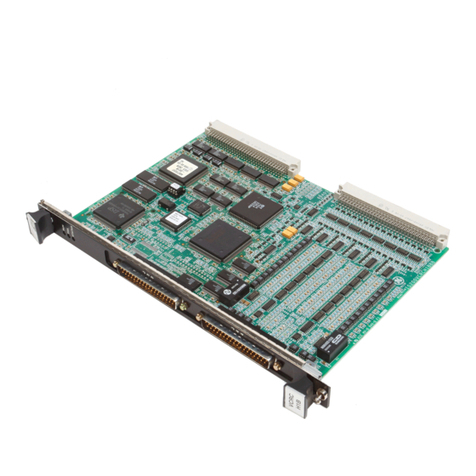
GE VMIVME-2533-010 Application guide

-~
ARTISAN
®
~I
TECHNOLOGY
GROUP
Your definitive source
for
quality
pre-owned
equipment.
Artisan Technology
Group
Full-service,
independent
repair
center
with
experienced
engineers
and
technicians
on staff.
We
buy
your
excess,
underutilized,
and
idle
equipment
along
with
credit
for
buybacks
and
trade-ins
.
Custom
engineering
so
your
equipment
works
exactly as
you
specify.
•
Critical
and
expedited
services
•
Leasing
/
Rentals/
Demos
• In
stock/
Ready-to-ship
•
!TAR-certified
secure
asset
solutions
Expert
team
ITrust
guarantee
I
100%
satisfaction
All
tr
ademarks,
br
a
nd
names, a
nd
br
a
nd
s a
pp
earing here
in
are
th
e property of
th
e
ir
r
es
pecti
ve
ow
ner
s.
Find the Abaco Systems / VMIC VMIVME-2533-010 at our website: Click HERE

GE
Intelligent Platforms
Publication No: 500-002533-000 Rev. L
Hardware Reference
VMIVME-2533*
Differential Digital Output Board
Artisan Technology Group - Quality Instrumentation ... Guaranteed | (888) 88-SOURCE | www.artisantg.com

Document History
Hardware Reference Document Number: 500-002533-000 Rev. L
May 25, 2010
Artisan Technology Group - Quality Instrumentation ... Guaranteed | (888) 88-SOURCE | www.artisantg.com

3
Table of Contents
List of Figures . . . . . . . . . . . . . . . . . . . . . . . . . . . . . . . . . . . . . . . . . . . . . . . . . . . . . . . . . . . . . . . . . . . . . 5
List of Tables . . . . . . . . . . . . . . . . . . . . . . . . . . . . . . . . . . . . . . . . . . . . . . . . . . . . . . . . . . . . . . . . . . . . . . 6
Overview . . . . . . . . . . . . . . . . . . . . . . . . . . . . . . . . . . . . . . . . . . . . . . . . . . . . . . . . . . . . . . . . . . . . . . . . . . 7
Features: . . . . . . . . . . . . . . . . . . . . . . . . . . . . . . . . . . . . . . . . . . . . . . . . . . . . . . . . . . . . . . . . . 7
Functional Description . . . . . . . . . . . . . . . . . . . . . . . . . . . . . . . . . . . . . . . . . . . . . . . . . . . . . . . . . . . . . 8
Functional Block Diagram. . . . . . . . . . . . . . . . . . . . . . . . . . . . . . . . . . . . . . . . . . . . . . . . . . . . . . . . . . 10
Reference Material List. . . . . . . . . . . . . . . . . . . . . . . . . . . . . . . . . . . . . . . . . . . . . . . . . . . . . . . . . . . . 11
Safety Summary . . . . . . . . . . . . . . . . . . . . . . . . . . . . . . . . . . . . . . . . . . . . . . . . . . . . . . . . . . . . . . . . . 12
Ground the System . . . . . . . . . . . . . . . . . . . . . . . . . . . . . . . . . . . . . . . . . . . . . . . . . . . . . . . . . . . 12
Do Not Operate in an Explosive Atmosphere . . . . . . . . . . . . . . . . . . . . . . . . . . . . . . . . . . . . . . . 12
Keep Away from Live Circuits . . . . . . . . . . . . . . . . . . . . . . . . . . . . . . . . . . . . . . . . . . . . . . . . . . . 12
Do Not Service or Adjust Alone . . . . . . . . . . . . . . . . . . . . . . . . . . . . . . . . . . . . . . . . . . . . . . . . . . 12
Do Not Substitute Parts or Modify System. . . . . . . . . . . . . . . . . . . . . . . . . . . . . . . . . . . . . . . . . . 12
Dangerous Procedure Warnings . . . . . . . . . . . . . . . . . . . . . . . . . . . . . . . . . . . . . . . . . . . . . . . . . 12
Safety Symbols Used in This Manual. . . . . . . . . . . . . . . . . . . . . . . . . . . . . . . . . . . . . . . . . . . . . . . . . 13
Chapter 1 - Theory of Operation . . . . . . . . . . . . . . . . . . . . . . . . . . . . . . . . . . . . . . . . . . . . . . . . . . . . . . 14
Operational Overview . . . . . . . . . . . . . . . . . . . . . . . . . . . . . . . . . . . . . . . . . . . . . . . . . . . . . . . . . . . . . 15
VMEbus Compatibility Logic . . . . . . . . . . . . . . . . . . . . . . . . . . . . . . . . . . . . . . . . . . . . . . . . . . . . 16
Device Addressing . . . . . . . . . . . . . . . . . . . . . . . . . . . . . . . . . . . . . . . . . . . . . . . . . . . . . . . . . . . . 17
Built-In-Test Description . . . . . . . . . . . . . . . . . . . . . . . . . . . . . . . . . . . . . . . . . . . . . . . . . . . . . . . . . . . 21
Chapter 2 - Configuration and Installation . . . . . . . . . . . . . . . . . . . . . . . . . . . . . . . . . . . . . . . . . . . . . . 22
Jumper Configuration . . . . . . . . . . . . . . . . . . . . . . . . . . . . . . . . . . . . . . . . . . . . . . . . . . . . . . . . . . . . . 23
Address Modifiers. . . . . . . . . . . . . . . . . . . . . . . . . . . . . . . . . . . . . . . . . . . . . . . . . . . . . . . . . . . . . . . . 24
Data Registers Base Address . . . . . . . . . . . . . . . . . . . . . . . . . . . . . . . . . . . . . . . . . . . . . . . . . . . . . . 25
CSR Base Address. . . . . . . . . . . . . . . . . . . . . . . . . . . . . . . . . . . . . . . . . . . . . . . . . . . . . . . . . . . . . . . 26
Artisan Technology Group - Quality Instrumentation ... Guaranteed | (888) 88-SOURCE | www.artisantg.com

Table of Contents
4
I/O Cable and Front Panel Connector Configuration . . . . . . . . . . . . . . . . . . . . . . . . . . . . . . . . . . . . . 27
Chapter 3 - Programming. . . . . . . . . . . . . . . . . . . . . . . . . . . . . . . . . . . . . . . . . . . . . . . . . . . . . . . . . . . . 31
Data Output . . . . . . . . . . . . . . . . . . . . . . . . . . . . . . . . . . . . . . . . . . . . . . . . . . . . . . . . . . . . . . . . . . . . 32
Data Loopback . . . . . . . . . . . . . . . . . . . . . . . . . . . . . . . . . . . . . . . . . . . . . . . . . . . . . . . . . . . . . . . . . . 33
Control and Status Register (CSR) . . . . . . . . . . . . . . . . . . . . . . . . . . . . . . . . . . . . . . . . . . . . . . . . . . 34
Maintenance . . . . . . . . . . . . . . . . . . . . . . . . . . . . . . . . . . . . . . . . . . . . . . . . . . . . . . . . . . . . . . . . . . . . . . 39
Artisan Technology Group - Quality Instrumentation ... Guaranteed | (888) 88-SOURCE | www.artisantg.com

5
List of Figures
Figure 1 Basic Digital Board Functions .................................................................................................... 8
Figure 2 Simplified Built-in-Test Functional Block Diagram ...................................................................... 9
Figure 3 VMIVME-2533 Functional Block Diagram .................................................................................10
Figure 1-1 Functional Block Diagram ........................................................................................................ 16
Figure 1-2 VMEbus Foundation Logic ........................................................................................................ 17
Figure 1-3 Address Decode Block Diagram ............................................................................................... 18
Figure 1-4 Data Transfer Block Diagram .................................................................................................... 19
Figure 1-5 CSR Block Diagram .................................................................................................................. 20
Figure 2-1 Jumper Locations ..................................................................................................................... 23
Figure 2-2 Address Modifier Positions ....................................................................................................... 24
Figure 2-3 Data Registers Base Address Configuration ............................................................................ 25
Figure 2-4 CSR Base Address Configuration ............................................................................................. 26
Figure 2-5 Cable Connector Configuration ................................................................................................. 27
Figure 2-6 P3 Connector Pin Layout .......................................................................................................... 28
Figure 2-7 P1/P2 Connector Pin Layout ..................................................................................................... 30
Artisan Technology Group - Quality Instrumentation ... Guaranteed | (888) 88-SOURCE | www.artisantg.com

6
List of Tables
Table 2-1 P3 Output Connector Channel Assignments . . . . . . . . . . . . . . . . . . . . . . . . . . . . . . . . . . . . . . . . . . . . . . . . . 29
Table 3-1 Address Register Bit Definitions . . . . . . . . . . . . . . . . . . . . . . . . . . . . . . . . . . . . . . . . . . . . . . . . . . . . . . . . . . . . . 33
Artisan Technology Group - Quality Instrumentation ... Guaranteed | (888) 88-SOURCE | www.artisantg.com

7
Overview
Introduction
The VMIVME-2533* is a VMEbus Compatible Differential Digital Output Board with
32 differential outputs channels.
Features:
• 32 bits of differential voltage outputs
• RS485/422 compatible drivers
• 8-, 16-, or 32-bit data transfers
• Each data bit represents one discrete line pair
•Built-in-test
• Front panel with Fail LED
• Compatible with the VMIVME-9016 Intelligent I/O Controller
Artisan Technology Group - Quality Instrumentation ... Guaranteed | (888) 88-SOURCE | www.artisantg.com
VMIVME-2533 Differential Digital Output Board
8
Functional Description
The VMIVME-2533 transfers digital data from the VMEbus backplane to RS485/422
compatible differential output drivers. The board will support byte, word, and
longword data transfers. A simplified functional block diagram of the board is
illustrated in Figure 1 below.
The VMIVME-2533 is designed with extensive Built-in-Test electronics that enable the
user to test most of the circuitry on the board. When the VMIVME-2533 is in test
mode, data, which is written to the output registers, can be read back to verify proper
operation. This can be done without driving the output cable, and without disturbing
the field circuitry connected to the VMIVME-2533. Figure 2 below shows a simplified
diagram of the Built-in-Test features of the VMIVME-2533.
Figure 1 Basic Digital Board Functions
CONTROL
LOGIC
OUTPUT
LOGIC
32 DIFFERENTIAL
VOLTAGE OUTPUTS
V
M
E
b
u
s
F
O
U
N
D
A
T
I
O
N
Artisan Technology Group - Quality Instrumentation ... Guaranteed | (888) 88-SOURCE | www.artisantg.com
Overview
9
Figure 2 Simplified Built-in-Test Functional Block Diagram
C
S
R
CONTROL
FAIL LED
TEST MODE 1
TEST MODE 2
P
A
L
CONTROL
9
34
CONTROL ENABLE ENABLE
O
U
T
P
U
T
R
E
G
I
S
T
E
R
S
32
32 BITS
OF DATA
32
C
A
B
L
E
D
R
I
V
E
R
S
32 64
C
A
B
L
E
R
E
C
E
I
V
E
R
S
O
U
T
P
U
T
C
O
N
N
E
C
T
O
R
Artisan Technology Group - Quality Instrumentation ... Guaranteed | (888) 88-SOURCE | www.artisantg.com
VMIVME-2533 Differential Digital Output Board
10
Functional Block Diagram
The VMIVME-2533 Differential Digital Output Board consists of VMEbus
compatibility logic, four 8-bit output registers, eight 4-bit differential line drivers, a
Control and Status Register, and eight 4-bit differential line receivers used by the
Built-in-Test logic, as shown in Figure 3 below.
The VMEbus compatibility logic controls data transfer allowing 8-, 16-, or 32-bit
VMEbus data transfers.
The four 8-bit output registers latch 32 bits of output data, which drives the eight
RS485/422 compatible differential output voltage drivers to the field connector.
The Control and Status Register (CSR) contains three bits. One bit controls the
on-board Fail LED, while the other two bits, along with some additional logic, control
the test functions of the board.
Built-in-Test logic enables the output data to be read back without affecting the signals
to the field. System reset puts the board into test mode for immediate loopback
testing.
Figure 3 VMIVME-2533 Functional Block Diagram
VMEbus
FOUNDATION
LOGIC
V
M
E
b
u
s
FOUR
8-BIT
OUTPUT
REGISTERS
DATA
BUS EIGHT
4-BIT
DIFFERENTIAL
LINE DRIVERS
32
DIFFERENTIAL
OUTPUTS
EIGHT
4-BIT
DIFFERENTIAL
LINE
RECEIVERS
FAIL LED
CSR AND
CONTROL
LOGIC
A
D
D
R
E
S
S
B
U
S
Artisan Technology Group - Quality Instrumentation ... Guaranteed | (888) 88-SOURCE | www.artisantg.com

Overview
11
Reference Material List
For a detailed description of the VMEbus, refer to The VMEbus Specification and
Handbook available from:
VMEbus International Trade Association (VITA)
7825 Gelding Dr. Suite No. 104
Scottsdale, AZ 85620-3415
(602) 951-8866
Fax: (602) 951-0720
Internet: www.vita.com
Physical Description and Specifications, refer to Product Specification, 800-002533-000
available from:
GE
12090 South Memorial Pkwy.
Huntsville, AL 35803-3308, USA
www.ge-ip.com
The following Application and Configuration Guides are available from GE to assist
the user in the selection, specification and implementation of systems based on GE's
products:
Title Document No.
Digital Input Board Application Guide 825-000000-000
Low Level Analog I/O Configuration Guide 825-000000-001
Change-of-State Application Guide 825-000000-002
Digital I/O (with Built-in-Test) Product Line Description 825-000000-003
Synchro/Resolver (Built-in-Test) Subsystem Application
Guide 825-000000-004
Analog I/O Products (with Built-in-Test) Configuration Guide 825-000000-005
Connector and I/O Cable Application Guide 825-000000-006
Artisan Technology Group - Quality Instrumentation ... Guaranteed | (888) 88-SOURCE | www.artisantg.com

VMIVME-2533 Differential Digital Output Board
12
Safety Summary
The following general safety precautions must be observed during all phases of the
operation, service, and repair of this product. Failure to comply with these
precautions or with specific warnings elsewhere in this manual violates safety
standards of design, manufacture, and intended use of this product.
GE assumes no liability for the customer's failure to comply with these requirements.
Ground the System
To minimize shock hazard, the chassis and system cabinet must be connected to an
electrical ground. A three-conductor AC power cable should be used. The power
cable must either be plugged into an approved three-contact electrical outlet or used
with a three-contact to two-contact adapter with the grounding wire (green) firmly
connected to an electrical ground (safety ground) at the power outlet.
Do Not Operate in an Explosive Atmosphere
Do not operate the system in the presence of flammable gases or fumes. Operation of
any electrical system in such an environment constitutes a definite safety hazard.
Keep Away from Live Circuits
Operating personnel must not remove product covers. Component replacement and
internal adjustments must be made by qualified maintenance personnel. Do not
replace components with power cable connected. Under certain conditions,
dangerous voltages may exist even with the power cable removed. To avoid injuries,
always disconnect power and discharge circuits before touching them.
Do Not Service or Adjust Alone
Do not attempt internal service or adjustment unless another person, capable of
rendering first aid and resuscitation, is present.
Do Not Substitute Parts or Modify System
Because of the danger of introducing additional hazards, do not install substitute
parts or perform any unauthorized modification to the product. Return the product
to GE for service and repair to ensure that safety features are maintained.
Dangerous Procedure Warnings
Warnings, such as the example below, precede only potentially dangerous procedures
throughout this manual. Instructions contained in the warnings must be followed.
STOP: Dangerous voltages, capable of causing death, are present in this system. Use
extreme caution when handling, testing, and adjusting.
Artisan Technology Group - Quality Instrumentation ... Guaranteed | (888) 88-SOURCE | www.artisantg.com

Overview
13
Safety Symbols Used in This Manual
STOP: This symbol informs the operator the that a practice or procedure should not
be performed. Actions could result in injury or death to personnel, or could result in
damage to or destruction of part or all of the system.
WA R N I N G : This sign denotes a hazard. It calls attention to a procedure, a practice, a
condition, which, if not correctly performed or adhered to, could result in injury or
death to personnel.
CAUTION: This sign denotes a hazard. It calls attention to an operating procedure, a
practice, or a condition, which, if not correctly performed or adhered to, could result
in damage to or destruction of part or all of the system.
NOTE: Calls attention to a procedure, a practice, a condition or the like, which is
essential to highlight.
Artisan Technology Group - Quality Instrumentation ... Guaranteed | (888) 88-SOURCE | www.artisantg.com

14
CHAPTER
Theory of Operation
Contents
Operational Overview. . . . . . . . . . . . . . . . . . . . . . . . . . . . . . . . . . . . . . . . . . . . . . . . 15
Built-In-Test Description . . . . . . . . . . . . . . . . . . . . . . . . . . . . . . . . . . . . . . . . . . . . . . 21
Introduction
This section of the manual presents detailed information concerning the hardware
operation of the board.
1
Artisan Technology Group - Quality Instrumentation ... Guaranteed | (888) 88-SOURCE | www.artisantg.com

15
Operational Overview 1
Operational Overview
The VMIVME-2533 consists of five primary sections as illustrated in Figure 1-1 below.
These sections are described in more detail in the following sections.
To perform an output data transfer, data is written into Output Data Registers (ODRs)
which latch the data. The latched data is used by the output driver stage of the board.
Artisan Technology Group - Quality Instrumentation ... Guaranteed | (888) 88-SOURCE | www.artisantg.com

16
1VMIVME-2533 Differential Digital Output Board
Figure 1-1 Functional Block Diagram
VMEbus Compatibility Logic
Typical VMEbus drivers, receivers, and control logic are shown in Figure 1-2 below.
The DTACK generator shown in Figure 1-2 is designed to select the maximum data
transfer speed.
BOARD SEL
PAL AND
CONTROL
RECEIVERS
ADDRESS
COMPARE
ADDRESS
JUMPERS
8-, 16-, 32-BIT
DATA TRANSFERS
32
13
3
R
E
G
I
S
T
E
R
S
O
U
T
P
U
T
D
R
I
V
E
R
S
32 32 64
16-BIT
ADDRESSING
V
M
E
b
u
s
DATA
TRANSCEIVERS
CSR
AND
CONTROL
LOGIC
TO FAIL LED
O
U
T
P
U
T
32 BITS OF
DIFFERENTIAL
OUTPUT VOLTAGES
ENABLE
R
E
C
E
I
V
E
R
S
I
N
P
U
T
32 64
ENABLE
AM0 to 5
Artisan Technology Group - Quality Instrumentation ... Guaranteed | (888) 88-SOURCE | www.artisantg.com
17
Operational Overview 1
Figure 1-2 VMEbus Foundation Logic
Device Addressing
The VMIVME-2533 is designed to support data transfers in supervisory or
non-privileged short I/O memory space or both. A jumper (AM02) is provided as
shown in Figure 1-3 on page 18 (Address Decode Block Diagram) to allow user
selection of either I/O access type or both. The jumper (AM02) is factory configured
(jumper AM02 not installed) to respond to short supervisory I/O access. Refer to
Configuration and Installation on page 22 for a detailed explanation of the address
modifier jumper.
The VMIVME-2533 is designed with a set of board select jumpers and decode logic as
shown in Figure 1-3 below to provide an efficient memory address map for CSR and
output data addresses. The board is also designed to handle 8-, 16-, or 32-bit data
transfers. Figure 1-4 on page 19 shows the block diagram of this circuitry.
P1
R
E
C
E
I
V
E
R
D
T
A
C
K
G
E
N
E
R
A
T
O
R
6
SYSTEM CLOCK
BOARD SELECT
DATA STROBE 1
DATA STROBE 2
READ/WRITE
ADDRESS STROBE
SYSTEM RESET
DELAY STROBE
DATA STROBE 0
DATA STROBE 1
DTACK*
V
M
E
b
u
s
SYSTEM CLOCK
Artisan Technology Group - Quality Instrumentation ... Guaranteed | (888) 88-SOURCE | www.artisantg.com
18
1VMIVME-2533 Differential Digital Output Board
Figure 1-3 Address Decode Block Diagram
C
O
M
P
A
R
A
T
O
R
=
AM0 to AM5
A8 to A15
THE AM2 JUMPER
SELECTS
NONPRIVILEGED OR
SUPERVISORY
SHORT I/O OR BOTH
C
O
M
P
A
R
A
T
O
R
=
C
O
M
P
A
R
A
T
O
R
=
J
U
M
P
E
R
S
8
A
D
D
R
E
S
S
A
D
D
R
E
S
S
J
U
M
P
E
R
S
V
M
E
b
u
s
P1
D
A
T
A
C
S
R
C
O
M
P
A
R
A
T
O
R
=
A
D
D
R
E
S
S
J
U
M
P
E
R
S
A
D
D
R
E
S
S
J
U
M
P
E
R
S
P
A
L
CSR SELECT
DATA SELECT
AM2
A2 to A7
A1 to A7
AM2
8
7
D
A
T
A
C
S
R
AM2 JUMPER
AM2 JUMPER
Artisan Technology Group - Quality Instrumentation ... Guaranteed | (888) 88-SOURCE | www.artisantg.com
19
Operational Overview 1
Figure 1-4 Data Transfer Block Diagram
T
R
A
N
S
C
E
I
V
E
R
T
R
A
N
S
C
E
I
V
E
R
T
R
A
N
S
C
E
I
V
E
R
WRITE/READ
IDB00 to IDB07
IDB08 to IDB15
IDB00 to IDB07
IDB16 to IDB23
P1
V
M
E
b
u
s
D00 to D07
D08 to D15
T
R
A
N
S
C
E
I
V
E
R
T
R
A
N
S
C
E
I
V
E
R
IDB08 to IDB15
IDB24 to IDB31
T
R
A
N
S
C
E
I
V
E
R
8
8
HI WORD DTA BUS EN L
D16 to D23
8
P2
D24 to D31
8
V
M
E
b
u
s
WRITE L LO WORD DATA BUS EN L
SEL HI WORD ONLY L
Artisan Technology Group - Quality Instrumentation ... Guaranteed | (888) 88-SOURCE | www.artisantg.com
This manual suits for next models
1
Table of contents
Other GE Computer Hardware manuals

GE
GE QuickPanel+ IC754VSI12MTD User manual

GE
GE D20MX User manual

GE
GE HO97929 User manual

GE
GE QuickPanel+ IC754VSI12CTD User manual

GE
GE IS200BAIAH B Series User manual

GE
GE VMIVME-2533 Series Application guide

GE
GE Mini Field Agent User manual

GE
GE D20MX User manual

GE
GE Profibus - DP Bus User manual

GE
GE ATS1290 User manual

GE
GE QuickPanel+ IC754VSB06CTD User manual

GE
GE VersaMax IC754TAN001 User manual

GE
GE IS200ADIIH A Series User manual

GE
GE IPN250RTM Quick user guide

GE
GE IC754VBI12CTD User manual

GE
GE IC754VGI08CTD User manual

GE
GE NPT6X User manual

GE
GE TELUM ASLP11 User manual

GE
GE D20MX User manual

GE
GE 90-30 PLC User manual