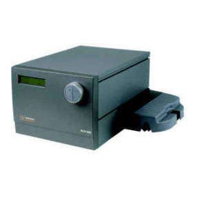
GE MicroCal iTC200 User manual

GE Healthcare
MicroCal™ iTC200 System
Operating Instructions
Original Instructions


MicroCal iTC200 Operating Instructions 28-9639-77 AA 3
Table of Contents
Table of Contents
1 Introduction .............................................................................. 5
1.1 Important user information ................................................................................. 6
1.2 Regulatory information ......................................................................................... 7
1.3 Instrument ................................................................................................................ 10
1.4 Control software .................................................................................................... 13
2 Safety instructions................................................................. 15
2.1 Safety precautions ............................................................................................... 15
2.2 Labels .......................................................................................................................... 21
2.3 Recycling procedures .......................................................................................... 25
3 Installation .............................................................................. 27
3.1 Site requirements .................................................................................................. 27
3.2 Transport ...................................................................................................................29
3.3 Unpacking ................................................................................................................. 29
3.4 Set up .......................................................................................................................... 29
3.5 Validation ..................................................................................................................37
3.6 Configuring a MicroCal iTC200 controller for networking .................... 38
4 Operation ................................................................................ 39
4.1 Procedure before a run ...................................................................................... 39
4.2 Basics of performing a run ............................................................................... 39
4.3 Loading the syringe ............................................................................................. 39
4.4 Loading the cell ...................................................................................................... 40
4.5 Experimental design ............................................................................................ 42
4.6 Advanced experimental design ...................................................................... 43
4.7 Instrument controls .............................................................................................. 44
4.8 Real time plot .......................................................................................................... 46
4.9 Set up .......................................................................................................................... 46
4.10 Procedures after a run ........................................................................................ 47
5 Maintenance ........................................................................... 49
5.1 Cell cleaning ............................................................................................................ 49
5.2 Removing injection syringe .............................................................................. 49
5.3 Inserting a new syringe ...................................................................................... 50
5.4 Syringe cleaning .................................................................................................... 51
5.5 Removing pipette .................................................................................................. 52
5.6 Changing pipette tips .......................................................................................... 53
5.7 Pipette calibration ................................................................................................. 54
5.8 Y-axis calibration check ..................................................................................... 54
5.9 Replacement of fuses ......................................................................................... 56
Table of Contents
4MicroCal iTC200 Operating Instructions 28-9639-77 AA
6 Troubleshooting..................................................................... 57
6.1 How to get help ...................................................................................................... 57
7 Reference information.......................................................... 59
7.1 Instrument specifications .................................................................................. 59
7.2 Ordering information ........................................................................................... 60

MicroCal iTC200 Operating Instructions 28-9639-77 AA 5
Introduction 1
1 Introduction
Purpose of the Operating
Instructions
The Operating Instructions provide you with the instructions needed to handle the
MicroCal iTC200 in a safe way.
Prerequisites
In order to operate the MicroCal iTC200 safely and according to the intended purpose the
following prerequisites must be met:
• You should have a general understanding of the use of a personal computer.
running Microsoft™ Windows™ in the version provided with your product.
• You should be acquainted with the use of general laboratory equipment and with
handling of biological materials.
• You must read the Safety Instructions in Chapter 2 of these Operating Instructions.
• The system should be installed according to the instructions in Chapter 3 of these
Operating Instructions.
• You should understand the concepts of titration Calorimetry.
• You must read and understand these Operating Instructions.
In this chapter
This chapter contains important user information and a general description of the
MicroCal iTC200 and its intended use.

1 Introduction
1.1 Important user information
6MicroCal iTC200 Operating Instructions 28-9639-77 AA
1.1 Important user information
Read this before using the
MicroCal iTC200
All users must read the Safety Instructions in Chapter 2 of these Operating Instructions
before installing, using or maintaining the system.
Do not operate the MicroCal iTC200 in any other way than described in the user
documentation. If you do, you may be exposed to hazards that can lead to personal
injury and you may cause damage to the equipment.
Intended use
The MicroCal iTC200 is an Isothermal Titration Calorimeter system designed for bio-
molecular interaction studies in research applications.
The MicroCal iTC200 system is intended for research use only and shall not be used in any
clinical procedures or for diagnostic purposes.
Safety notices
These Operating Instructions contain WARNINGS, CAUTIONS and NOTICES concerning
the use of the product, with meanings as defined below.
WARNING
WARNING indicates a hazardous situation which, if not avoided, could
result in death or serious injury. It is important not to proceed until all
stated conditions are met and clearly understood.
CAUTION
CAUTION indicates a hazardous situation which, if not avoided, could
result in minor or moderate injury. It is important not to proceed until all
stated conditions are met and clearly understood.
NOTICE
NOTICE indicates instructions that must be followed to avoid damage to
the product or other equipment.

MicroCal iTC200 Operating Instructions 28-9639-77 AA 7
Introduction 1
Regulatory information 1.2
Notes and tips
Note: A Note is used to indicate information that is important for trouble-free and
optimal use of the product.
Tip: A tip contains useful information that can improve or optimize your procedures.
Typographical conventions
Software texts and commands are identified by bold italic text. A colon is used to
separate menu levels (e.g. File:Open refers to the Open option in the File menu).
1.2 Regulatory information
This section lists the directives and standards that are fulfilled by MicroCal iTC200.
Manufacturing information
CE conformity
Requirement Content
Name and address of manufacturer GE Healthcare
MicroCal Products Group
22 Industrial Drive East
Northampton, Massachusetts
01060 USA
Place and date of declaration Northampton, Massachusetts,
USA, Jan. 2010
Identity of person authorized to sign
Declaration of Conformity
See EC Declaration of Conformity in
system documentation kit.
Date of manufacture and serial
number
The serial number contains the
code for the year of the
manufacture of the instrument.
(the serial number takes the form
of) xx.yy.zzz where
yy = year of manufacture.
Directive Title
2006/42/EC Machinery Directive (MD)
2006/95/EC Low Voltage Directive (LVD)

1 Introduction
1.2 Regulatory information
8MicroCal iTC200 Operating Instructions 28-9639-77 AA
International standards
CE marking
The CE marking and the corresponding Declaration of Conformity is valid for the
instrument when it is:
• used as a stand-alone unit, or
• connected to other CE-marked instruments, or
• connected to other products recommended or described in the user
documentation, and
• used in the same state as it was delivered from GE Healthcare, except for
alterations described in the user documentation or explicitly authorized by GE
Healthcare.
2004/108/EC ElectroMagnetic Compatibility (EMC) Directive
Directive Title
Standard Description Notes
EN 61010-1,
IEC 61010-1,
CAN/CSA-C22.2
no. 61010-1
Safety requirements for electrical
equipment for measurement,
control and laboratory use
EN 61326-1
(CISPR Group 1,
Class A)
EMC emissions and immunity
requirements for measurement,
control and laboratory use
Harmonized with
2004/108/EC
EN-ISO 12100-1,
12100-2
Safety of machinery – Basic
concepts, general principles and
design
Harmonized with
2006/42/EC
EN-ISO 14121-1,
14121-2
Safety of machinery – Principles of
risk assessment
Harmonized with
2006/42/EC

MicroCal iTC200 Operating Instructions 28-9639-77 AA 9
Introduction 1
Regulatory information 1.2
Regulatory compliance of
connected equipment
Any equipment connected to the MicroCal iTC200 should meet the safety requirements
of EN 61010-1/IEC61010-1 or relevant harmonized standards. Within the European
Union, connected equipment must be CE-marked.

1 Introduction
1.3 Instrument
10 MicroCal iTC200 Operating Instructions 28-9639-77 AA
1.3 Instrument
The MicroCal iTC200 (Isothermal Titration Calorimeter, 200 µL cell) unit directly measures
heat evolved or absorbed in liquid samples as a result of mixing precise amounts of
reactants. A spinning syringe is utilized for injecting and mixing of reactants. Spin rates
are user selectable; the usual range is 500 to 1000 rpm. The normal temperature
operating range is 2°C to 80°C. Wetted cell surfaces are Hastalloy, which are resistant
to most solutions, however, strong acids should be avoided.
Sample and reference cells are accessible for filling and cleaning through the top of the
unit. The sample cell is on the left as one faces the front of the unit. A pair of identical
coin shaped cells is enclosed within two shields; the inner shield is referred to as the
jacket. Access stems travel from the top exterior of the instrument to the cells. Both the
coin shaped cells and the access stems are completely filled with liquid during
operation. This requires approximately 280 µL per cell even though the working volume
of the cell is only 200 µL.
Figure 1-1. Principle drawing of ITC.
Part Description Part Description
1Pipette 5Samplecell(withsyringe)
2 Plunger screw (dark blue) 6 Adiabatic jackets
3 Stirring motor 7 Reference cell
4 Syringe (light blue) 8 Outer shield

MicroCal iTC200 Operating Instructions 28-9639-77 AA 11
Introduction 1
Instrument 1.3
Figure 1-2. MicroCal iTC200 complete system.
Temperature differences between the reference cell and the sample cell are measured,
calibrated to power units and displayed to the user as well as saved to disk. The data
channel is referred to as the DP signal, or the differential power between the reference
cell and the sample cell. This signal is sometimes thought of as the "feedback" power
used to maintain temperature equilibrium. Calibration of this signal is obtained
electrically by administering a known quantity of power through a resistive heater
element located on the cell.
In a typical experiment, the syringe containing a ligand is titrated (injected) into the cell
containing a solution of macromolecule. An injection which results in the evolution of
heat (exothermic) within the sample cell causes a negative change in the DP power,
since the heat evolved chemically provides heat that the DP feedback is no longer
required to provide.
The opposite is true for endothermic reactions. Since the DP has units of power, the time
integral of the peak yields a measurement of thermal energy, dH. This heat is released
or absorbed in direct proportion to the amount of binding that occurs. When the
macromolecule in the cell becomes saturated with added ligand, the heat signal
diminishes until only the background heat of dilution is observed.
Part Description Part Description
1 Controller 4 Washing module
2 MicroCal iTC200 5Tower
3 Pipette 6 Cell Unit
1
2
3
4
5
6

1 Introduction
1.3 Instrument
12 MicroCal iTC200 Operating Instructions 28-9639-77 AA
With the MicroCal iTC200 system the entire experiment takes place under computer
control. The user inputs the experimental parameters (temperature, number of
injections, injection volumes) and the computer carries out the experiment.
<DoNotTranslate_GE_Color>Origin™ software is then used to analyze the ITC data
using fitting models to calculate reaction stoichiometry (n), binding constant (KA),
enthalpy (ΔH) and entropy (ΔS).

MicroCal iTC200 Operating Instructions 28-9639-77 AA 13
Introduction 1
Control software 1.4
1.4 Control software
In order for the system to initialize properly, all components must be powered up in the
correct order. First, boot up the computer and log in to Windows. Once Windows has
started, power the MicroCal iTC200 by operating the switch at the rear of the unit. After
several seconds, open the MicroCal iTC200 software. If the option is selected, a real-time
copy of <DoNotTranslate_GE_Color>Origin will open automatically, as well as the
MicroCal iTC200 control software.
Figure 1-3. Instrument control software.
When the instrument first boots up, the line just below the menus reads "System
Initialization - Please Wait", which is the current status of the instrument. After a few
seconds, the system will begin heating or cooling to the preset temperature. If the
instrument is not attached or not turned on, the program will open into Demo Mode, in
which the user can see and manipulate the program, but it will not attempt to control
the MicroCal iTC200. To the right of the status bar, the Time Left box, during a run, will
show the time left until the end of the run.
When the software is first started, the Experimental Design tab is selected; this
contains the simple run controls. Experimental Mode can be Highest Quality, Minimum
Protein, or High Speed. The expected n, KD, and ΔH and the desired run temperature will
allow the software to calculate the recommended concentrations for the cell and
syringe, and set the run parameters. The Advanced Experimental Design tab contains
more direct controls for the more advanced user. This tab should be very familiar to
users of the VP line of instruments. The Instrument Controls tab allows the user to
name the output files, choose post-run analysis options, and start and stop the run. The
Real Time Plot tab shows the data currently being generated. The Setup tab contains
various options and preferences.

1 Introduction
1.4 Control software
14 MicroCal iTC200 Operating Instructions 28-9639-77 AA
Origin software
Origin Real-Time Display
This section describes the functionality of the optional copy of
<DoNotTranslate_GE_Color>Origin for real-time display. When the software is opened,
it will open the <DoNotTranslate_GE_Color>Origin™ project window VPITCPLOT.OPJ for
real time data display. This project of <DoNotTranslate_GE_Color>Origin is dedicated to
data display only, and should not be used for data analysis. Users should open a
separate copy of <DoNotTranslate_GE_Color>Origin for MicroCal iTC200 to perform data
analysis. Pictured below is the main <DoNotTranslate_GE_Color>Origin window for
MicroCal iTC200 data display.
Figure 1-4. <DoNotTranslate_GE_Color>Origin Real-Time display.
The ITC cell status, the MicroCal iTC200 numeric display and the buttons for MicroCal
iTC200 data tools (as indicated above) have been added for user convenience in viewing
data generated by the MicroCal iTC200. For a more thorough description of these real-
No. Description
1iTCcellstatus
2iTCnumericdisplay
3 Buttons for iTC data display
1
2
3

MicroCal iTC200 Operating Instructions 28-9639-77 AA 15
Introduction 1
Control software 1.4
time tools in <DoNotTranslate_GE_Color>Origin, refer to the MicroCal iTC200
Experimental and Data Analysis Tutorial Guide.

1 Introduction
1.4 Control software
16 MicroCal iTC200 Operating Instructions 28-9639-77 AA

MicroCal iTC200 Operating Instructions 28-9639-77 AA 15
Safety instructions 2
Safety precautions 2.1
2 Safety instructions
The points below are intended to enhance your safety awareness and to draw your
attention to risks which only you, the operator, can prevent. While GE Healthcare works
to ensure that the instrument is designed and tested to be as safe as possible, proper
handling is also critical. The operators should be responsible people trained in basic
laboratory protocol, and they should be familiar with the possible hazards before
operating this instrument. All instrument modifications should be performed only by
personnel trained by GE Healthcare. Equipment damage, personal injury or even death
may result if this equipment is operated, altered or maintained by untrained personnel
or in an irresponsible or improper manner.
2.1 Safety precautions
Introduction
Before installing, operating of maintaining the system, you must be aware of the
hazards described in the user documentation. Follow the instructions provided to avoid
personal injury or damage to the equipment.
The safety precautions in this section are grouped into the following categories:
• General precautions
• Flammable liquids
• Personal protection
• Installing and moving the instrument
•Systemoperation
•Maintenance

2 Safety instructions
2.1 Safety precautions
16 MicroCal iTC200 Operating Instructions 28-9639-77 AA
General precautions
WARNING!
Provide proper electrical power to the instrument. This should be 100 –
240 Volt, 50/60 Hertz alternating current, with a Ground Fault Circuit
Interrupter (GFCI). Some power strips, such as the one provided by GE
Healthcare with your instrument, contain a GFCI. All power plugs and
cords should be 3-prong, grounded cables or outlets.
WARNING!
In case of fire, unplug instrument.
WARNING!
Do not operate the MicroCal iTC200 in any other way than described in
the MicroCal iTC200 and/or Auto-MicroCal iTC200 manuals.
WARNING!
Make sure the rear power connector is always accessible.
WARNING!
Use caution when using solutions near the instrument. If any liquid is
spilled on or around the instrument, unplug the instrument immediately
and wipe it up. If there is any possibility that liquid may have leaked into
the instrument case, contact GE Healthcare immediately. Do not plug
the instrument into any electrical outlet until the problem is resolved.
WARNING!
This instrument is not designed to the Medical Devices Directive 93/42/
EEC and should not be used for medical purposes and/or in the
diagnosis of patients.
NOTICE
The MicroCal iTC200 cells are constructed out of Hastelloy. Strong acids
should be avoided.

MicroCal iTC200 Operating Instructions 28-9639-77 AA 17
Safety instructions 2
Safety precautions 2.1
Using flammable liquids
Personal protection
WARNING!
A fume hood or similar ventilation system shall be installed when
flammable or noxious substances are used.
WARNING!
Fire Hazard. Before starting the system make sure that there is no
leakage.
WARNING!
Always use protective glasses and other personal protective equipment
appropriate with the current application, to ensure personal safety
during operation.
WARNING!
The operator should always follow proper laboratory procedures in
handling and disposing of volatile or hazardous solutions.
WARNING!
This instrument is used for a wide variety of experiments that can utilize
potentially hazardous materials. Use of these could cause exposure to
biological, chemical and radiation hazards depending on the user’s
experiments. Users should educate themselves about the samples they
are using to avoid these hazards.

2 Safety instructions
2.1 Safety precautions
18 MicroCal iTC200 Operating Instructions 28-9639-77 AA
Installing and moving the
instrument
System operation
WARNING!
Power cord. Only use power cords delivered or approved by GE
Healthcare.
WARNING!
Do not block the ventilation inlets or outlets on the system.
WARNING!
The Washing Module may only be powered by the power supply
provided with the Unit.
WARNING!
Installing the controller. The controller should be installed and used
according to the instructions provided by the documentation included
in the shipment.
WARNING!
Replace fuses ONLY with 4.00 Amp 250 Volt Time Delay Fuses. Several
spare fuses are provided with the original shipment.
WARNING!
Access to power switch and power cord. Do not block the rear and side
panel of the instrument. The Power switch must always be easy to
access. The power cord must always be easy to disconnect.
NOTICE
Disconnect power. To prevent equipment damage, always disconnect
power from the MicroCal iTC200 and washing module system before an
instrument module is removed or installed or a cable is connected or
disconnected.
WARNING!
All solutions in the cells must be cooled down below 40ºC before
removal. Any higher temperature may cause the syringe to break, and
will increase the dangers of most hazardous solutions.
Table of contents
Other GE Laboratory Equipment manuals

GE
GE AKTA avant User manual

GE
GE AxiChrom 50 User manual

GE
GE AKTAprocess Operating instructions

GE
GE ImageQuant LAS 500 Operating instructions

GE
GE ReadyToProcess WAVE 25 User manual

GE
GE Monitor UV-900 User manual

GE
GE AKTA ready User manual

GE
GE AKTApure User manual

GE
GE Amersham Imager 680 User manual

GE
GE AKTApure User manual