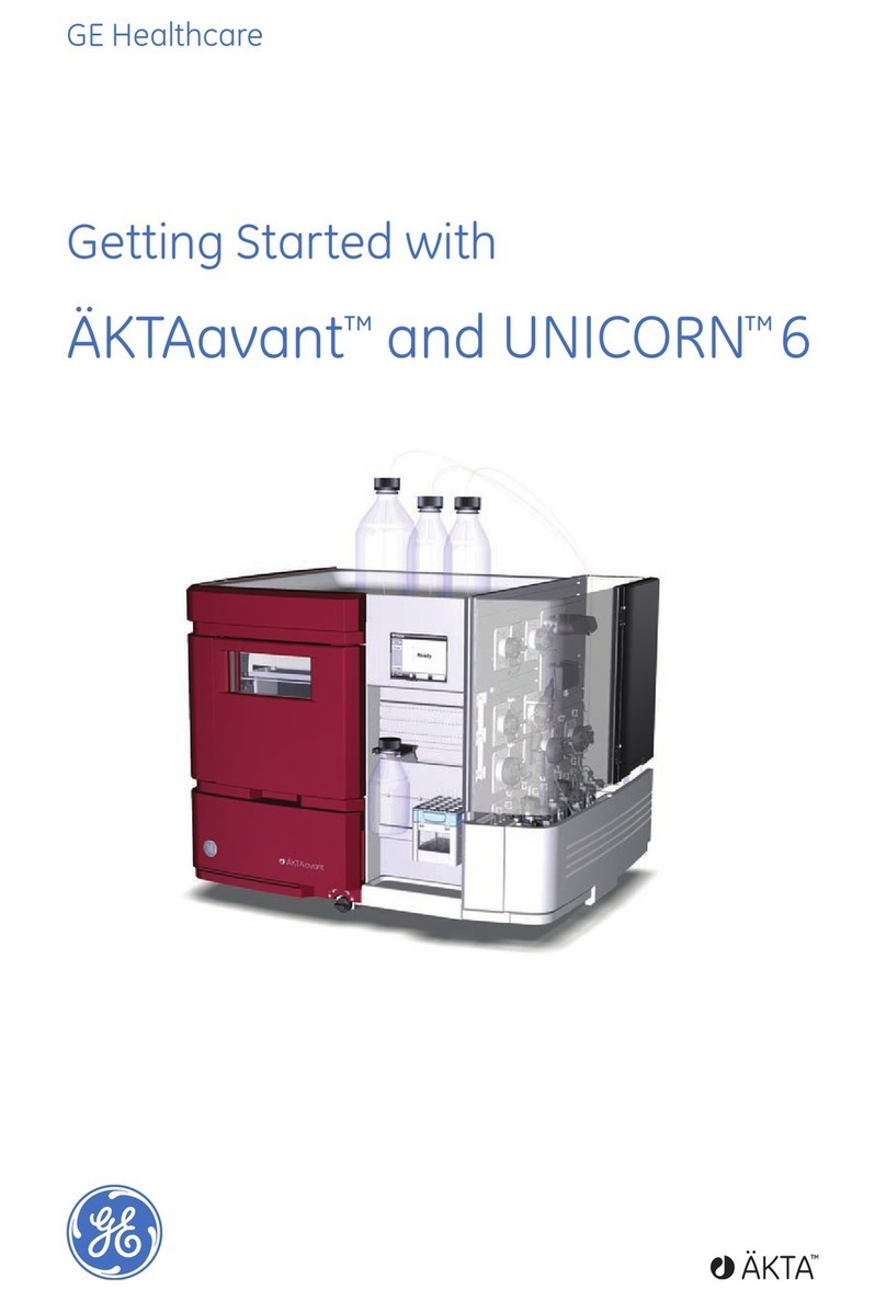
GE Monitor UV-900 User manual

ÄKTA™
Monitor UV-900
User Manual
GE Healthcare


Important user information
All users must read this entire manual to fully under-
stand the safe use of Monitor UV-900.
WARNING!
The WARNING! sign highlights instructions
that must be followed to avoid personal
injury. It is important not to proceed until
all stated conditions are met and clearly
understood.
CAUTION!
The Caution! sign highlights instructions that must be
followed to avoid damage to the product or other equip-
ment. It is important not to proceed until all stated con-
ditions are met and clearly understood.
Note
The Note sign is used to indicate information important
for trouble-free and optimal use of the product.
CE Certifying
This product meets the requirements of applicable CE-
directives. A copy of the corresponding Declaration of
Conformity is available on request.
The
CE
symbol and corresponding declaration of confor-
mity, is valid for the instrument when it is:
– used as a stand-alone unit, or
– connected to other CE-marked GE Healthcare
instruments, or
– connected to other products recommended or
described in this manual, and
– used in the same state as it was delivered from GE
Healthcare except for alterations described in this
manual.
Recycling
This symbol indicates that the waste of
electrical and electronic equipment must
not be disposed as unsorted municipal
waste and must be collected separately.
Please contact an authorized representa-
tive of the manufacturer for information
concerning the decommissioning of equip-
ment.
WARNING!
This is a Class A pruduct. In a domestic environment this
product may cause radio interference in which case the
user may be required to make adequate measures
Monitor UV-900 User Manual 18-1120-05 Edition AF


Monitor UV-900 User Manual 18-1120-05 Edition AF
V
Contents
1 Introduction
1.1 General ................................................................................................7
1.2 Safety ...................................................................................................8
2 Installation
2.1 Unpacking ..........................................................................................9
2.2 General precautions .....................................................................9
2.3 Installing the flow cell ................................................................ 10
2.3.1 Fixing the flow cell .................................................................... 10
2.3.2 Connecting the optical fibers ............................................... 11
2.4 Connecting electrical signal cables .................................... 12
2.4.1 Connecting to recorder (if used).......................................... 12
2.5 Connecting to communication link ..................................... 12
2.6 Connecting to supply voltage ............................................... 13
2.7 Connecting the tubing .............................................................. 13
2.8 Mounting the cell holder cover ............................................. 14
3Operation
3.1 On/off ................................................................................................ 15
3.2 Menu selection and settings .................................................. 15
3.2.1 Menu selection ........................................................................... 15
3.2.2 Return to main menu .............................................................. 16
3.2.3 Select value.................................................................................. 16
3.3 Main menu overview ................................................................. 17
3.4 Setting lamp on/off ..................................................................... 17
3.5 Reading absorbance values ................................................... 18
3.6 Setting wavelength ..................................................................... 18
3.7 Autozero .......................................................................................... 19
3.8 Storage and shut-down ........................................................... 19
3.9 Using an external chart recorder ........................................ 20
3.9.1 Setting range and zero ........................................................... 20
3.9.2 Event mark ................................................................................... 20
3.10 Filtering noise ................................................................................ 21
3.11 UV cell calibration ....................................................................... 22
3.12 Changing flow cell ....................................................................... 24
3.13 Restart after power failure ...................................................... 24
4 Maintenance
4.1 Periodic maintenance ............................................................... 25

Contents
VI
Monitor UV-900 User Manual 18-1120-05 Edition AF
4.2 Cleaning-in-place .........................................................................25
4.3 Checking the instrument ..........................................................26
4.3.1 Lamp intensity ............................................................................26
4.3.2 Lamp on–time .............................................................................26
4.3.3 Flip time..........................................................................................26
4.3.4 UV flow cell ...................................................................................26
4.4 Cleaning the flow cell and optical fiber connectors ....27
4.4.1 Cleaning the flow cell...............................................................27
4.4.2 Cleaning the optical fiber connectors...............................27
4.4.3 Instrument housing...................................................................27
4.5 ..................................................................Cleaning the system 27
4.6 Recycling ..........................................................................................28
5 Trouble-shooting
5.1 General .............................................................................................29
5.2 Faults and actions .......................................................................29
5.3 Error messages .............................................................................30
Reference information
A Description ........................................................................................................ 31
A.1
Instrument
............................................................................................................31
A.2
Flow cell
.................................................................................................................32
A.3
Monitor principle
................................................................................................32
B Menus .................................................................................................................. 34
B.1
Check menu
.........................................................................................................34
B.2
Setup menu
..........................................................................................................36
B.3
Setting and using the alarm timer
.............................................................37
B.4
Service displays
..................................................................................................37
B.5
Menu overview
...................................................................................................38
C Technical specifications ............................................................................. 39
D Accessories and spare parts ....................................................................42
Short instructions on side 39
About this manual
This manual comprises two parts; a practical part
(sections 1–5) and a reference part (sections A-D).
Sections 1–5 contain the necessary information for operating the
instrument.

Introduction 1
Monitor UV-900 User Manual 18-1120-05 Edition AF
7
1 Introduction
1.1 General
Monitor UV-900 is a UV-absorption monitor for use in liquid chromatography.
Monitor UV-900 features:
• Variable wavelength for detection in the range 190–700 nm.
• Up to 3 wavelengths can be monitored simultaneously.
• Two alternative flow cells with path length 2 mm and 10 mm.
• Accurate and reliable monitoring through self-test, self-calibration and
fiber optics.
Monitor UV-900

1Introduction
8
Monitor UV-900 User Manual 18-1120-05 Edition AF
1.2 Safety
• The instrument is designed for indoor use only.
• Do not use in a dusty atmosphere or close to spraying water.
IMPORTANT!
Monitor UV-900 is intended for laboratory use only, not for
clinical or in vitro use, or for diagnostic purposes.
WARNING!
When using hazardous chemicals, all suitable protective
measures, such as protective glasses, must be taken.
WARNING
! The instruments must not be opened by the user. They contain
high voltage circuits which can give a lethal electric shock.
WARNING
! The system must be connected to a grounded mains socket.
WARNING
! Always disconnect the power supply before attempting to
replace any item on the instrument.
WARNING!
The instrument uses high intensity ultra-violet light. Do not
disconnect the optical fibers while the monitor is running.
CAUTION!
The flow cell must not be used at pressures above 2 MPa (20 bar,
290 psi). At higher pressures the flow cell may break.
WARNING!
When using hazardous chemicals, take all suitable protective
measures, such as wearing protective glasses and gloves resistant to the
chemicals used. Follow local regulations and instructions for safe operation
and maintenance of the system.
WARNING!
There must always be a sample loop connected to ports 2 and 6
of the injection valve. This is to prevent liquid spraying out of the ports when
switching the valve. This is especially dangerous if hazardous chemicals are
used.
WARNING!
This is a Class A product. In domestic environment this product
may cause radio interference in which the user may be required to take
adequate measures.

Installation 2
Monitor UV-900 User Manual 18-1120-05 Edition AF
9
2 Installation
2.1 Unpacking
Unpack the instrument and check the items against the supplied packing list.
Inspect the items for obvious damage which may have occurred during
transportation
.
• The system should be installed on a stable laboratory bench providing a
suitable working area.
• To maintain correct ventilation, the system requires an appropriate
amount of free space. Do not block the ventilation inlets or outlets on the
system!
It is recommended that all packing materials should be retained if onward
transport of the instrument is expected.
2.2 General precautions
The instrument should not be installed in a corrosive atmosphere or in an
atmosphere where deposits are liable to form on the optical surfaces.
The instrument should be located in a place of low temperature variations,
away from heat sources, draughts and direct sunlight.
The instrument may be operated at normal ambient temperatures in the range
+4 to +40 °C.
The instrument should be installed on a stable laboratory bench or in
ÄKTA
™
explorer or ÄKTApurifier. To ensure correct ventilation a free space of
0.1 m is required behind and in front of the instrument. Place the instrument
directly on the bench. Do not use any soft material under the instrument, to
ensure that the ventilation inlet in the front is not blocked.
CAUTION!
The following information should be read carefully to ensure that
the instrument is installed correctly.
Monitor UV-900

2Installation
10
Monitor UV-900 User Manual 18-1120-05 Edition AF
2.3 Installing the flow cell
2.3.1 Fixing the flow cell
Handle the optical fibers with care,
do not bend excessively.
Two flow cells are available: UV-900/2 with 2 mm light path length
(cell volume 2 µl) and UV-900/10 with 10 mm path length (8 µl).
1 Unpack the flow cell. Do not remove the red protective caps from the inlet
or outlet, or the black protective caps on the optical fiber connectors.
2 Slide the rear white clip on the cell holder to its inner position for a 2 mm
cell and to its outer position for the 10 mm cell.
3 Place the flow cell in the opening between the white clips. The cell should
be positioned with the text and serial number facing upwards and to the
front. Press the cell into the clips to fasten it.
10 mm 2 mm
CAUTION!
To avoid damaging the optical fibers, press only on the cell body,
never on the optical fibers.

Installation 2
Monitor UV-900 User Manual 18-1120-05 Edition AF
11
To improve the access to the tubing connections, the flow cell canalternatively
be positioned with the tubing connections.
2.3.2 Connecting the optical fibers
1 Remove the 2 black protective caps from the optical fiber connectors.
2 Remove the 2 rubber protective caps from the optical fiber receptacles on
the right side of the housing.
3 Connect the 2 optical fibers to the housing by carefully inserting them into
the sockets and tightening the nuts fingertight using the fiber detachment
tool supplied.
4 Slide the rubber sleeves on the 2 optical fibers onto the connectors. Make
sure that the sleeves are pushed tight to the housing to prevent dust or
fluid entering the connection.
Serial number
Normal position
Serial number
Alternative position
CAUTION
!
Do not touch the tips of the optical fibers with your fingers as
this will result in poor monitor performance. If you accidentally touch the
optical fiber tip, it can be wiped with 30% isopropanol using lens pape
r.
Fiber
detachmen
t
tool
CAUTION!
Do not twist the optical fibers during tightening.
Rubber sleeve

2Installation
12
Monitor UV-900 User Manual 18-1120-05 Edition AF
2.4 Connecting electrical signal cables
The sockets for electrical signals are located on the back panel.
2.4.1 Connecting to recorder (if used)
1 Connect the recorder to the miniDIN-socket
Analogue out
using the cable
supplied. Each wavelength signal is available on a separate channel using
the following wires:
Note:
The signal cable is delivered with protective covers on each wire. Do
not remove the protective covers from unused connections as a
short circuit may disturb the measurements.
2 Set the recorder to 0–1 V input, full scale, 0 V offset.
2.5 Connecting to communication link
The monitor can be used in ÄKTAexplorer or ÄKTApurifier and controlled from a
PC running UNICORN
™
version 3.21 or higher, using UniNet cables.
Analogue out
0-1V Remote UniNet 1 Mains On/off
λ
1 Wire 1 +
Wire 2 –
λ
2 Wire 3 +
Wire 4 -
λ
3 Wire 5 +
Wire 6 -
CAUTION!
The mains power to the ÄKTAexplorer or ÄKTApurifier must be
switched OFF before connecting the instrument to the UniNet-1 link.
WARNING!
Only use mains cables delivered or approved by GE Healthcare.
WARNING!
Do not block the rear panel of the system. The mains power
switch must always be easy to access.

Installation 2
Monitor UV-900 User Manual 18-1120-05 Edition AF
13
Connect two UniNet cables to the UniNet-1 connectors. The instrument can be
connected in series anywhere in the chain between the PC and the termination
plug. The UniNet-1 link connects, in series, the PC with Pump P-905,
Monitor pH/C-900 and Monitor UV-900. The termination plug is connected to
the last instrument in the chain.
2.6 Connecting to supply voltage
1 Make sure the on/off switch is in the OFF position (
O
).
2 Connect a mains cable between the instrument and a grounded mains
socket. The instrument is delivered with both European and US type mains
cables, as standard. Any voltage 100–240 V AC, 50–60 Hz, can be used.
The instrument contains no user replaceable fuse.
2.7 Connecting the tubing
1 Remove the red protective caps from the inlet and outlet of the flow cell
and connect the tubing with 1/16" “fingertights”.
The inlet is on the top of the flow cell, the same side as the serial number.
WARNING!
The instrument must be connected to a grounded mains socket.
Inlet
Outlet

Installation 2
Monitor UV-900 User Manual 18-1120-05 Edition AF
14
2.8 Mounting the cell holder cover
The cover is a simple push fit onto the cell holder. Two small lugs on the cover
locate in holes at the front and rear of the cell holder The cover is then lowered
over the cell holder.

Operation 3
Monitor UV-900 User Manual 18-1120-05 Edition AF
15
3 Operation
3.1 On/off
1 Switch on the instrument at the mains switch on the rear panel.
2 The instrument performs a self-test and then starts calibration.
3 If the instrument has a calibrated cell path length set that differs from the
nominal length, a warning message appears on the monitor display.
Another message, displaying the calibrated cell length, also appears. The
display toggles between these messages.
4 To go to the
Main operating menu
, press
OK
or wait for about 45 seconds
to return automatically.
5 If no such warning messages appear, the display automatically shows the
Main operating menu
after approximately 1 minute. The instrument is
ready to use.
All parameters are factory set to default values.
3.2 Menu selection and settings
3.2.1 Menu selection
A specific menu is selected by turning the front selection dial clockwise or
counter clockwise. When the required menu is visible the menu or selection is
accepted by pressing the
OK
button.
Selftest
Please wait...
Calibrating
Please wait...
Please Check UV Cell!
Press OK/Esc to cont.
Real UV Cell Length
(?,??mm, SN??????
λ1(215) 1.123 AU
λ2(254) 0.02345 AU
Menu selection
OK
button
ESC
button
Select submenu Return one menu level

3Operation
16
Monitor UV-900 User Manual 18-1120-05 Edition AF
If a menu has sub levels, the sub menu is displayed by pressing the
OK
button. Pressing the
ESC
button moves back one menu level.
3.2.2 Return to main menu
Pressing
ESC
repeatedly, always returns to the
main menu 2
which is the main
operating menu. Press
ESC
once more to return to
main menu 1
, the mode
changing menu.
3.2.3 Select value
A cursor below a text or numerical value shows what is affected by the dial. To
increase the value turn the dial clockwise. To decrease the value turn the dial
counter clockwise.
When setting numerical values, the cursor moves up to the next digit if the dial
is turned quickly in one direction, to simplify entering large values. The cursor
moves back one place to the right every two seconds if the dial is not turned.
The text or numerical value displayed is accepted by pressing the
OK
button.
To cancel, press the
ESC
button.
Sub menu 3.3.1
Sub menu 3.3.2
Main menu 1
Main menu 2
Main menu 3
Main menu 4
Main menu 5
Sub menu 3.1
Sub menu 3.2
Sub menu 3.3
Sub menu 3.1.1
ESC
OK
ESC
OK
ESC
OK
Main menus Sub menus Sub menus
Main menu 1
Main menu 2 ESC ESC ESC ESC
ESC
Parameter
Current value New value to be set
Set Wavelength
(280 nm) 250.0

Operation 3
Monitor UV-900 User Manual 18-1120-05 Edition AF
17
3.3 Main menu overview
Mode changing menu (mode menu)
.The menu is accessed from all positions by
pressing the
ESC
button repeatedly.
Main operating menu 1
. Wavelength display showing first two wavelengths
and, if the instrument is in Run mode, their absorbance.
Main operating menu 2
. Wavelength display showing the third wavelength and,
if the instrument is in Run mode, the absorbance.
Autozero the instrument.
Produce event mark.
Set the wavelengths for the measurements.
Set the recorder output
.
Filtering noise.
Flow cell path length calibration.
Check internal operating values.
See section
B.1 Check menu.
Setup language, unit number etc.
See section
B.2 Setup menu.
Set different timer options.
See section
B.3 Setting and using the alarm timer.
3.4 Setting lamp on/off
The lamp should be switched off when no measurement is made to conserve
the lamp operating time. The lamp is switched on when a run is started. No
warm-up time is required.
1 Select the mode changing menu.
2 Switch the lamp on (
Run
) or off (
End
) by pressing
OK
. Its current status is
shown in the upper left of the display.
When controlled from UNICORN, the lamp is switched on automatically when
the flow is started and off when the run is ended.
Run
Press OK to End
λ1(215) 1.123 AU
λ2(254) 0.02345 AU
λ3(280) 1.123 AU
Autozero
Eventmark
Set Wavelength
(215, 254, 280 nm)
Set Analogue Out
(2.000AUFS, 10%)
Set Averaging Time
(2,56s)
Set UV Cell Length
(--.-- mm, SN ------)
Check
Setup
Alarm/Timer 00:22:24
Current status
Run
Press OK to End

3Operation
18
Monitor UV-900 User Manual 18-1120-05 Edition AF
3.5 Reading absorbance values
The main operating menu shows the absorbance values for up to 3 active
wavelengths. The menu is reached from any other menu by pressing the
ESC
button repeatedly. The display for the third wavelength is reached by turning
the dial clockwise.
As an alternative all3 wavelengths can be shown ina single display, butlimited
to 3 decimals. This alternative is reached by turning the dial clockwise.
3.6 Setting wavelength
The instrument can measure up to 3 wavelengths simultaneously and
wavelength changes can be set at any time.
1 Select main menu
Set Wavelength
, press
OK
.
2 Select sub menu
Set Wavelength
λ
1
, press
OK
.
3 Set the value, press
OK
.
4 The next wavelength
λ
2
is now shown. Set the value or turn the
wavelength off, by turning the dial counter clockwiseuntil the valuepasses
through 190 nm. If only one wavelength is to be used,
λ2
and
λ3
should be
set to off. Press
OK
.
The first wavelength
λ
1
can never be set to off.
5 Repeat step 4 in the menu
Set Wavelength
λ
3
.
6 Press
ESC
to return to the main operating menu.
In UNICORN, the wavelengths are set with the instruction
Wavelength
in
System Control:Manual:Alarm&Mon
.
λ1(215) 1.123 AU
λ2(254) 0.02345 AU
λ3(280) 1.123 AU
or
215nm 254nm 280nm
1.123 0.023 0.123
Set Wavelength
(215, 254, 280 nm)
Set Wavelength λ1
(215, 254, 280 nm)
Set Wavelength λ1
(215nm) 234
Set Wavelength λ2
(254nm)

Operation 3
Monitor UV-900 User Manual 18-1120-05 Edition AF
19
3.7 Autozero
The autozero function sets the detected absorbance to zero when the
OK
button is pressed. All three wavelengths are autozeroed. Autozero is
recommended after wavelength changes in a method and before the sample
is injected.
1 Select main menu
Autozero
, press
OK
. The normal absorbance value
display is then shown.
In UNICORN, Autozero is set with the instruction
AutoZeroUV
in
System
Control:Manual:Alarm&Mon
.
3.8 Storage and shut-down
Overnight:
The flow cell can be left filled with buffer.
Weekend and long term storage:
Flush the flow cell with distilled water and
then fill it with 20% ethanol.
The flow cell can also be stored dry by flushing as above with distilled water
and then blowing a compressed inert gas such as nitrogen (N
2
) through the cell.
Replace the red protective caps. Never use compressed air as this may contain
droplets of oil.
Autozero
CAUTION!
Do not allow solutions which contain dissolved salts, proteins or
other solid solutions to dry out in the flow cell. Do not allow particles to
enter the flow cell as damage to the flow cell may occur.

3Operation
20
Monitor UV-900 User Manual 18-1120-05 Edition AF
3.9 Using an external chart recorder
3.9.1 Setting range and zero
The external chart recorder output from the instrument is always 0–1 V, but the
absorbance value for fullscale deflection and the Zero Absorbance level on the
recorder can be set.
1 Select main menu
Set Analogue Out
, press
OK
.
2 Set the range value in the sub menu
Set Range
and press
OK
. The range is
the full scale absorbance range for the chart recorder (1 V). Only fixed
steps between 5.0 AU and 0.01 AU can be set and the value is the same for
all 3 wavelengths.
3 Select menu
Set Zero Level
, press
OK
.
4 Set the value and press
OK
. This value determines where the zero
absorbance level should be in relation to full scale on the recorder.
The instrument has an automatic overrange
function. If during a peak the monitor signal
reaches the full scale value, the signal will drop
instantly to 0 V and give an accurate display of
the peak starting from this position.
3.9.2 Event mark
Event marks can be set, for example when the
sample is injected, and displayed as spikes on all
three channels of the chart recorder. The spikes are
10% of the full scale of the chart recorder which
corresponds to 0.1 V.
1 Select main menu
Event mark
,
press
OK
.
Set Analogue Out
(2.000AUFS, 10%)
Set Range
(2.000AUFS) <0.1>
Set Zero Level
(10% of FS) 20
Range
AU
Overrange
Measured absorbance
level (A U)
Signal to
recorder (V)
0 V
1 V
Table of contents
Other GE Laboratory Equipment manuals

GE
GE AKTAprocess User manual

GE
GE AKTA GO User manual

GE
GE ReadyToProcess WAVE 25 User manual

GE
GE akta start User manual

GE
GE AKTA avant User manual

GE
GE akta start User manual

GE
GE Whatman Mini-UniPrep G2 User manual

GE
GE Frac-920 User manual

GE
GE Autosampler User manual

GE
GE AKTApilot Operating instructions
Popular Laboratory Equipment manuals by other brands

Planet
Planet IPOE-175 user manual

AQUA EL
AQUA EL PS-9W operating instructions

KIKKA BOO
KIKKA BOO TWILL Instructions for use

PerkinElmer
PerkinElmer aanalyst 200 user guide

PerkinElmer
PerkinElmer RamanFlex 400 Series Getting started guide

Cooper Surgical
Cooper Surgical RI Witness 6-70-854 quick start guide