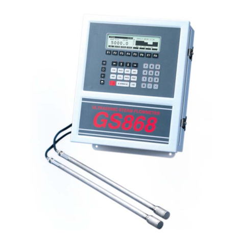
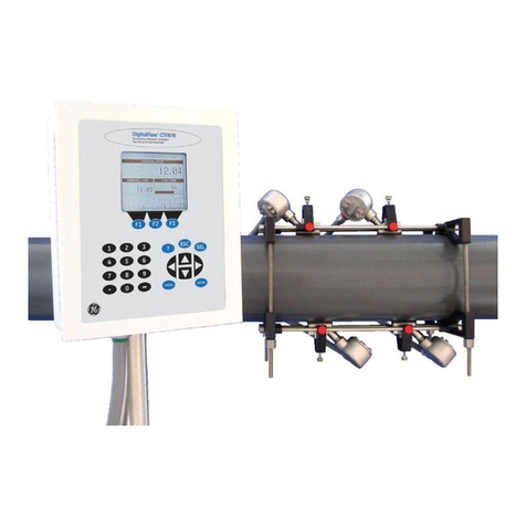
GE DigitalFlow DF868 Owner's manual

GE
Sensing & Inspection Technologies
DigitalFlow™ DF868
Panametrics Multipurpose Ultrasonic Liquid Flowmeter
Programming Manual (2-Channel)

GE
Sensing & Inspection Technologies
DigitalFlow™ DF868
Panametrics Multipurpose Ultrasonic Liquid Flowmeter
Programming Manual (2-Channel)
910-176P2D1
March 2008
The DigitalFlow DF868 is a GE Panametrics product. GE Panametrics has joined other GE high-technology
businesses under a new name—GE Sensing & Inspection Technology.

iii
March 2008
Warranty Each instrument manufactured by GE Sensing, Inc. is warranted to be
free from defects in material and workmanship. Liability under this
warranty is limited to restoring the instrument to normal operation or
replacing the instrument, at the sole discretion of GE. Fuses and
batteries are specifically excluded from any liability. This warranty is
effective from the date of delivery to the original purchaser. If GE
determines that the equipment was defective, the warranty period is:
•one year for general electronic failures of the instrument
•one year for mechanical failures of the sensor
If GE determines that the equipment was damaged by misuse,
improper installation, the use of unauthorized replacement parts, or
operating conditions outside the guidelines specified by GE, the
repairs are not covered under this warranty.
The warranties set forth herein are exclusive and are in lieu of
all other warranties whether statutory, express or implied
(including warranties of merchantability and fitness for a
particular purpose, and warranties arising from course of
dealing or usage or trade).
Return Policy If a GE Sensing, Inc. instrument malfunctions within the warranty
period, the following procedure must be completed:
1. Notify GE, giving full details of the problem, and provide the model
number and serial number of the instrument. If the nature of the
problem indicates the need for factory service, GE will issue a
RETURN AUTHORIZATION number (RA), and shipping instructions
for the return of the instrument to a service center will be
provided.
2. If GE instructs you to send your instrument to a service center, it
must be shipped prepaid to the authorized repair station indicated
in the shipping instructions.
3. Upon receipt, GE will evaluate the instrument to determine the
cause of the malfunction.
Then, one of the following courses of action will then be taken:
•If the damage is covered under the terms of the warranty, the
instrument will be repaired at no cost to the owner and returned.
•If GE determines that the damage is not covered under the terms
of the warranty, or if the warranty has expired, an estimate for the
cost of the repairs at standard rates will be provided. Upon receipt
of the owner’s approval to proceed, the instrument will be repaired
and returned.

v
March 2008
Table of Contents
Chapter 1: Programming Site Data
Introduction . . . . . . . . . . . . . . . . . . . . . . . . . . . . . . . . . . . . . . . . . . . . . . . . . . . . . . . . . . . . . . . . . . . . . . . . . . . . . . . 1-1
Using the Keypad . . . . . . . . . . . . . . . . . . . . . . . . . . . . . . . . . . . . . . . . . . . . . . . . . . . . . . . . . . . . . . . . . . . . . . . . . . 1-2
Obtaining On-line Help . . . . . . . . . . . . . . . . . . . . . . . . . . . . . . . . . . . . . . . . . . . . . . . . . . . . . . . . . . . . . . . . . . . . . 1-6
Using the Console Control Keys . . . . . . . . . . . . . . . . . . . . . . . . . . . . . . . . . . . . . . . . . . . . . . . . . . . . . . . . . . . . . 1-7
Adjusting the Alarm Volume . . . . . . . . . . . . . . . . . . . . . . . . . . . . . . . . . . . . . . . . . . . . . . . . . . . . . . . . . . . . 1-7
Using the Stopwatch Totalizer . . . . . . . . . . . . . . . . . . . . . . . . . . . . . . . . . . . . . . . . . . . . . . . . . . . . . . . . . . 1-7
Adjusting the Brightness . . . . . . . . . . . . . . . . . . . . . . . . . . . . . . . . . . . . . . . . . . . . . . . . . . . . . . . . . . . . . . . . 1-7
Adjusting the Contrast . . . . . . . . . . . . . . . . . . . . . . . . . . . . . . . . . . . . . . . . . . . . . . . . . . . . . . . . . . . . . . . . . . 1-7
Entering Programming Mode . . . . . . . . . . . . . . . . . . . . . . . . . . . . . . . . . . . . . . . . . . . . . . . . . . . . . . . . . . . . . . . 1-8
Entering Programming Mode . . . . . . . . . . . . . . . . . . . . . . . . . . . . . . . . . . . . . . . . . . . . . . . . . . . . . . . . . . . 1-8
Entering Channel Data . . . . . . . . . . . . . . . . . . . . . . . . . . . . . . . . . . . . . . . . . . . . . . . . . . . . . . . . . . . . . . . . . . . . . 1-9
Activating a Channel . . . . . . . . . . . . . . . . . . . . . . . . . . . . . . . . . . . . . . . . . . . . . . . . . . . . . . . . . . . . . . . . . . . 1-9
Entering System Data for a Channel. . . . . . . . . . . . . . . . . . . . . . . . . . . . . . . . . . . . . . . . . . . . . . . . . . . .1-10
Entering Pipe Data . . . . . . . . . . . . . . . . . . . . . . . . . . . . . . . . . . . . . . . . . . . . . . . . . . . . . . . . . . . . . . . . . . . .1-16
Setting Up Inputs/Outputs . . . . . . . . . . . . . . . . . . . . . . . . . . . . . . . . . . . . . . . . . . . . . . . . . . . . . . . . . . . . .1-22
Entering Setup Data . . . . . . . . . . . . . . . . . . . . . . . . . . . . . . . . . . . . . . . . . . . . . . . . . . . . . . . . . . . . . . . . . . . 1-25
Entering Global Data . . . . . . . . . . . . . . . . . . . . . . . . . . . . . . . . . . . . . . . . . . . . . . . . . . . . . . . . . . . . . . . . . . . . . .1-38
Setting the Clock . . . . . . . . . . . . . . . . . . . . . . . . . . . . . . . . . . . . . . . . . . . . . . . . . . . . . . . . . . . . . . . . . . . . . . 1-39
Setting the Date . . . . . . . . . . . . . . . . . . . . . . . . . . . . . . . . . . . . . . . . . . . . . . . . . . . . . . . . . . . . . . . . . . . . . . . 1-39
Setting the Time. . . . . . . . . . . . . . . . . . . . . . . . . . . . . . . . . . . . . . . . . . . . . . . . . . . . . . . . . . . . . . . . . . . . . . .1-39
Entering Global System Data. . . . . . . . . . . . . . . . . . . . . . . . . . . . . . . . . . . . . . . . . . . . . . . . . . . . . . . . . . .1-41
Setting Up Global Inputs/Outputs . . . . . . . . . . . . . . . . . . . . . . . . . . . . . . . . . . . . . . . . . . . . . . . . . . . . . . 1-45
Setting Up Serial Communications . . . . . . . . . . . . . . . . . . . . . . . . . . . . . . . . . . . . . . . . . . . . . . . . . . . . . 1-54
MODBUS (RS485) Parameters . . . . . . . . . . . . . . . . . . . . . . . . . . . . . . . . . . . . . . . . . . . . . . . . . . . . . . . . . . 1-55
MODBUS/TCP Parameters . . . . . . . . . . . . . . . . . . . . . . . . . . . . . . . . . . . . . . . . . . . . . . . . . . . . . . . . . . . . . 1-55
MODBUS Register Map . . . . . . . . . . . . . . . . . . . . . . . . . . . . . . . . . . . . . . . . . . . . . . . . . . . . . . . . . . . . . . . .1-56
Entering KV vs. SS Tables . . . . . . . . . . . . . . . . . . . . . . . . . . . . . . . . . . . . . . . . . . . . . . . . . . . . . . . . . . . . . .1-60
Entering Temperature vs. Viscosity Tables . . . . . . . . . . . . . . . . . . . . . . . . . . . . . . . . . . . . . . . . . . . . . .1-61
Activating Security . . . . . . . . . . . . . . . . . . . . . . . . . . . . . . . . . . . . . . . . . . . . . . . . . . . . . . . . . . . . . . . . . . . .1-63
Saving Site Data . . . . . . . . . . . . . . . . . . . . . . . . . . . . . . . . . . . . . . . . . . . . . . . . . . . . . . . . . . . . . . . . . . . . . . . . . .1-65
Recalling Site Data . . . . . . . . . . . . . . . . . . . . . . . . . . . . . . . . . . . . . . . . . . . . . . . . . . . . . . . . . . . . . . . . . . . . . . . .1-66
Chapter 2: Displaying Data
Introduction . . . . . . . . . . . . . . . . . . . . . . . . . . . . . . . . . . . . . . . . . . . . . . . . . . . . . . . . . . . . . . . . . . . . . . . . . . . . . . . 2-1
The BIG Submenu . . . . . . . . . . . . . . . . . . . . . . . . . . . . . . . . . . . . . . . . . . . . . . . . . . . . . . . . . . . . . . . . . . . . . . . . . . 2-2
The DUAL Submenu . . . . . . . . . . . . . . . . . . . . . . . . . . . . . . . . . . . . . . . . . . . . . . . . . . . . . . . . . . . . . . . . . . . . . . . . 2-3
The GRAPH Submenu. . . . . . . . . . . . . . . . . . . . . . . . . . . . . . . . . . . . . . . . . . . . . . . . . . . . . . . . . . . . . . . . . . . . . . . 2-4
Setting Up the GRAPH Format. . . . . . . . . . . . . . . . . . . . . . . . . . . . . . . . . . . . . . . . . . . . . . . . . . . . . . . . . . . 2-4
Using the GRAPH Format . . . . . . . . . . . . . . . . . . . . . . . . . . . . . . . . . . . . . . . . . . . . . . . . . . . . . . . . . . . . . . . 2-5
The LOG Submenu . . . . . . . . . . . . . . . . . . . . . . . . . . . . . . . . . . . . . . . . . . . . . . . . . . . . . . . . . . . . . . . . . . . . . . . . . 2-7
Entering the LOG Submenu . . . . . . . . . . . . . . . . . . . . . . . . . . . . . . . . . . . . . . . . . . . . . . . . . . . . . . . . . . . . . 2-7
Numeric Format. . . . . . . . . . . . . . . . . . . . . . . . . . . . . . . . . . . . . . . . . . . . . . . . . . . . . . . . . . . . . . . . . . . . . . . . 2-8
Graphical Format. . . . . . . . . . . . . . . . . . . . . . . . . . . . . . . . . . . . . . . . . . . . . . . . . . . . . . . . . . . . . . . . . . . . . . . 2-9
Displaying the Transducer Signal . . . . . . . . . . . . . . . . . . . . . . . . . . . . . . . . . . . . . . . . . . . . . . . . . . . . . . . . . . 2-11
Setting the LCD Backlight . . . . . . . . . . . . . . . . . . . . . . . . . . . . . . . . . . . . . . . . . . . . . . . . . . . . . . . . . . . . . . . . . .2-14

March 2008
vi
Table of Contents (cont.)
Chapter 3: Logging Data
Introduction . . . . . . . . . . . . . . . . . . . . . . . . . . . . . . . . . . . . . . . . . . . . . . . . . . . . . . . . . . . . . . . . . . . . . . . . . . . . . . . 3-1
Creating a Standard Log . . . . . . . . . . . . . . . . . . . . . . . . . . . . . . . . . . . . . . . . . . . . . . . . . . . . . . . . . . . . . . . . . . . 3-2
Log Type. . . . . . . . . . . . . . . . . . . . . . . . . . . . . . . . . . . . . . . . . . . . . . . . . . . . . . . . . . . . . . . . . . . . . . . . . . . . . . . 3-4
STARTTIME Prompt . . . . . . . . . . . . . . . . . . . . . . . . . . . . . . . . . . . . . . . . . . . . . . . . . . . . . . . . . . . . . . . . . . . . . 3-4
START DATE Prompt . . . . . . . . . . . . . . . . . . . . . . . . . . . . . . . . . . . . . . . . . . . . . . . . . . . . . . . . . . . . . . . . . . . . 3-4
END TIME Prompt . . . . . . . . . . . . . . . . . . . . . . . . . . . . . . . . . . . . . . . . . . . . . . . . . . . . . . . . . . . . . . . . . . . . . . 3-5
END DATE Prompt . . . . . . . . . . . . . . . . . . . . . . . . . . . . . . . . . . . . . . . . . . . . . . . . . . . . . . . . . . . . . . . . . . . . . . 3-5
DURATION Prompt . . . . . . . . . . . . . . . . . . . . . . . . . . . . . . . . . . . . . . . . . . . . . . . . . . . . . . . . . . . . . . . . . . . . . 3-5
LOG TIME Prompt . . . . . . . . . . . . . . . . . . . . . . . . . . . . . . . . . . . . . . . . . . . . . . . . . . . . . . . . . . . . . . . . . . . . . . 3-6
TIME INCREMENT Prompt . . . . . . . . . . . . . . . . . . . . . . . . . . . . . . . . . . . . . . . . . . . . . . . . . . . . . . . . . . . . . . . 3-6
Checking the Memory . . . . . . . . . . . . . . . . . . . . . . . . . . . . . . . . . . . . . . . . . . . . . . . . . . . . . . . . . . . . . . . . . . . . . . 3-7
Stopping a Log. . . . . . . . . . . . . . . . . . . . . . . . . . . . . . . . . . . . . . . . . . . . . . . . . . . . . . . . . . . . . . . . . . . . . . . . . . . . . 3-8
Creating an ERROR Log. . . . . . . . . . . . . . . . . . . . . . . . . . . . . . . . . . . . . . . . . . . . . . . . . . . . . . . . . . . . . . . . . . . . . 3-9
Log Type. . . . . . . . . . . . . . . . . . . . . . . . . . . . . . . . . . . . . . . . . . . . . . . . . . . . . . . . . . . . . . . . . . . . . . . . . . . . . . 3-11
STARTTIME Prompt . . . . . . . . . . . . . . . . . . . . . . . . . . . . . . . . . . . . . . . . . . . . . . . . . . . . . . . . . . . . . . . . . . . . 3-11
START DATE Prompt . . . . . . . . . . . . . . . . . . . . . . . . . . . . . . . . . . . . . . . . . . . . . . . . . . . . . . . . . . . . . . . . . . . 3-11
Chapter 4: Printing Data
Introduction . . . . . . . . . . . . . . . . . . . . . . . . . . . . . . . . . . . . . . . . . . . . . . . . . . . . . . . . . . . . . . . . . . . . . . . . . . . . . . . 4-1
Setting Up a Printer . . . . . . . . . . . . . . . . . . . . . . . . . . . . . . . . . . . . . . . . . . . . . . . . . . . . . . . . . . . . . . . . . . . . . . . . 4-2
Print Live Data . . . . . . . . . . . . . . . . . . . . . . . . . . . . . . . . . . . . . . . . . . . . . . . . . . . . . . . . . . . . . . . . . . . . . . . . . . . . . 4-3
Numeric Format . . . . . . . . . . . . . . . . . . . . . . . . . . . . . . . . . . . . . . . . . . . . . . . . . . . . . . . . . . . . . . . . . . . . . . . 4-3
Graphical Format . . . . . . . . . . . . . . . . . . . . . . . . . . . . . . . . . . . . . . . . . . . . . . . . . . . . . . . . . . . . . . . . . . . . . . 4-5
Printing Logs. . . . . . . . . . . . . . . . . . . . . . . . . . . . . . . . . . . . . . . . . . . . . . . . . . . . . . . . . . . . . . . . . . . . . . . . . . . . . . . 4-6
Numeric Format . . . . . . . . . . . . . . . . . . . . . . . . . . . . . . . . . . . . . . . . . . . . . . . . . . . . . . . . . . . . . . . . . . . . . . . 4-7
Graphical Format . . . . . . . . . . . . . . . . . . . . . . . . . . . . . . . . . . . . . . . . . . . . . . . . . . . . . . . . . . . . . . . . . . . . . . 4-7
Print Site File. . . . . . . . . . . . . . . . . . . . . . . . . . . . . . . . . . . . . . . . . . . . . . . . . . . . . . . . . . . . . . . . . . . . . . . . . . . . . . . 4-8
Stop Printing. . . . . . . . . . . . . . . . . . . . . . . . . . . . . . . . . . . . . . . . . . . . . . . . . . . . . . . . . . . . . . . . . . . . . . . . . . . . . . . 4-9
Chapter 5: Clearing Data
Introduction . . . . . . . . . . . . . . . . . . . . . . . . . . . . . . . . . . . . . . . . . . . . . . . . . . . . . . . . . . . . . . . . . . . . . . . . . . . . . . . 5-1
Clearing Totalized Data. . . . . . . . . . . . . . . . . . . . . . . . . . . . . . . . . . . . . . . . . . . . . . . . . . . . . . . . . . . . . . . . . . . . . 5-2
Deleting Site Files . . . . . . . . . . . . . . . . . . . . . . . . . . . . . . . . . . . . . . . . . . . . . . . . . . . . . . . . . . . . . . . . . . . . . . . . . . 5-2
Deleting Log Files . . . . . . . . . . . . . . . . . . . . . . . . . . . . . . . . . . . . . . . . . . . . . . . . . . . . . . . . . . . . . . . . . . . . . . . . . . 5-3
Chapter 6: Serial Communications
Introduction . . . . . . . . . . . . . . . . . . . . . . . . . . . . . . . . . . . . . . . . . . . . . . . . . . . . . . . . . . . . . . . . . . . . . . . . . . . . . . . 6-1
Wiring the RS232 Interface . . . . . . . . . . . . . . . . . . . . . . . . . . . . . . . . . . . . . . . . . . . . . . . . . . . . . . . . . . . . . . . . . 6-1
Checking the DF868 Baud Rate . . . . . . . . . . . . . . . . . . . . . . . . . . . . . . . . . . . . . . . . . . . . . . . . . . . . . . . . . . . . . 6-2
Setting Up the Terminal Software . . . . . . . . . . . . . . . . . . . . . . . . . . . . . . . . . . . . . . . . . . . . . . . . . . . . . . . . . . . 6-2
The Optional RS485 Serial Interface . . . . . . . . . . . . . . . . . . . . . . . . . . . . . . . . . . . . . . . . . . . . . . . . . . . . . . . . . 6-3
Interface Converter Mounting. . . . . . . . . . . . . . . . . . . . . . . . . . . . . . . . . . . . . . . . . . . . . . . . . . . . . . . . . . . 6-3
Point-To-Point Wiring. . . . . . . . . . . . . . . . . . . . . . . . . . . . . . . . . . . . . . . . . . . . . . . . . . . . . . . . . . . . . . . . . . . 6-4
Multi-Point Wiring . . . . . . . . . . . . . . . . . . . . . . . . . . . . . . . . . . . . . . . . . . . . . . . . . . . . . . . . . . . . . . . . . . . . . . 6-5
Setting Up an Ethernet Connection . . . . . . . . . . . . . . . . . . . . . . . . . . . . . . . . . . . . . . . . . . . . . . . . . . . . . . . . . 6-8
Setting Up a MODBUS/TCP Connection. . . . . . . . . . . . . . . . . . . . . . . . . . . . . . . . . . . . . . . . . . . . . . . . . . . . . . 6-9

vii
March 2008
Table of Contents (cont.)
Appendix A: Menu Maps
Appendix B: Data Records
Option Cards Installed . . . . . . . . . . . . . . . . . . . . . . . . . . . . . . . . . . . . . . . . . . . . . . . . . . . . . . . . . . . . . . . . . . . . . . B-1
Initial Setup Data. . . . . . . . . . . . . . . . . . . . . . . . . . . . . . . . . . . . . . . . . . . . . . . . . . . . . . . . . . . . . . . . . . . . . . . . . . . B-2
Appendix C: Programming with PanaView
Introduction . . . . . . . . . . . . . . . . . . . . . . . . . . . . . . . . . . . . . . . . . . . . . . . . . . . . . . . . . . . . . . . . . . . . . . . . . . . . . . . C-1
Wiring the RS232 Interface . . . . . . . . . . . . . . . . . . . . . . . . . . . . . . . . . . . . . . . . . . . . . . . . . . . . . . . . . . . . . . . . . C-1
Wiring the Ethernet Interface . . . . . . . . . . . . . . . . . . . . . . . . . . . . . . . . . . . . . . . . . . . . . . . . . . . . . . . . . . . . . . . C-1
Setting Up the Communications Port. . . . . . . . . . . . . . . . . . . . . . . . . . . . . . . . . . . . . . . . . . . . . . . . . . . . . . . . C-2
Setting up Ethernet Communications. . . . . . . . . . . . . . . . . . . . . . . . . . . . . . . . . . . . . . . . . . . . . . . . . . . . C-4
Adding the DF868 . . . . . . . . . . . . . . . . . . . . . . . . . . . . . . . . . . . . . . . . . . . . . . . . . . . . . . . . . . . . . . . . . . . . . . . . . . C-5
Editing Meter Properties . . . . . . . . . . . . . . . . . . . . . . . . . . . . . . . . . . . . . . . . . . . . . . . . . . . . . . . . . . . . . . . . . . . . C-7
Setting the Meter Clock . . . . . . . . . . . . . . . . . . . . . . . . . . . . . . . . . . . . . . . . . . . . . . . . . . . . . . . . . . . . . . . . . C-9
Reading Transducer Signals . . . . . . . . . . . . . . . . . . . . . . . . . . . . . . . . . . . . . . . . . . . . . . . . . . . . . . . . . . .C-10
Plotting Transducer Signals . . . . . . . . . . . . . . . . . . . . . . . . . . . . . . . . . . . . . . . . . . . . . . . . . . . . . . . . . . . .C-11
Saving Transducer Signals . . . . . . . . . . . . . . . . . . . . . . . . . . . . . . . . . . . . . . . . . . . . . . . . . . . . . . . . . . . . .C-11
Clearing Totalizers. . . . . . . . . . . . . . . . . . . . . . . . . . . . . . . . . . . . . . . . . . . . . . . . . . . . . . . . . . . . . . . . . . . . .C-11
Handling Site Files. . . . . . . . . . . . . . . . . . . . . . . . . . . . . . . . . . . . . . . . . . . . . . . . . . . . . . . . . . . . . . . . . . . . .C-12
Changing Meter Settings . . . . . . . . . . . . . . . . . . . . . . . . . . . . . . . . . . . . . . . . . . . . . . . . . . . . . . . . . . . . . . . . . .C-15
Appendix D: Foundation Fieldbus Communications
Optional Measurements . . . . . . . . . . . . . . . . . . . . . . . . . . . . . . . . . . . . . . . . . . . . . . . . . . . . . . . . . . . . . . . . . . . .D-1
Configuration Utility Setup. . . . . . . . . . . . . . . . . . . . . . . . . . . . . . . . . . . . . . . . . . . . . . . . . . . . . . . . . . . . . . . . . .D-2
Selecting the Desired Measurements. . . . . . . . . . . . . . . . . . . . . . . . . . . . . . . . . . . . . . . . . . . . . . . . . . . . . . . .D-2
Selecting Units for AI Blocks . . . . . . . . . . . . . . . . . . . . . . . . . . . . . . . . . . . . . . . . . . . . . . . . . . . . . . . . . . . . . . . .D-4
Resetting Instrument Totalizers . . . . . . . . . . . . . . . . . . . . . . . . . . . . . . . . . . . . . . . . . . . . . . . . . . . . . . . . . . . . .D-5
Function Block Application. . . . . . . . . . . . . . . . . . . . . . . . . . . . . . . . . . . . . . . . . . . . . . . . . . . . . . . . . . . . . . . . . .D-6

Chapter 1

Programming Site Data
Introduction. . . . . . . . . . . . . . . . . . . . . . . . . . . . . . . . . . . . . . . . . . . . . . . . . . . . 1-1
Using the Keypad . . . . . . . . . . . . . . . . . . . . . . . . . . . . . . . . . . . . . . . . . . . . . . . 1-2
Obtaining On-line Help . . . . . . . . . . . . . . . . . . . . . . . . . . . . . . . . . . . . . . . . . . 1-6
Using the Console Control Keys . . . . . . . . . . . . . . . . . . . . . . . . . . . . . . . . . . 1-7
Entering Programming Mode . . . . . . . . . . . . . . . . . . . . . . . . . . . . . . . . . . . . 1-8
Entering Channel Data . . . . . . . . . . . . . . . . . . . . . . . . . . . . . . . . . . . . . . . . . . 1-9
Entering Global Data. . . . . . . . . . . . . . . . . . . . . . . . . . . . . . . . . . . . . . . . . . . 1-38
Saving Site Data . . . . . . . . . . . . . . . . . . . . . . . . . . . . . . . . . . . . . . . . . . . . . . . 1-65
Recalling Site Data. . . . . . . . . . . . . . . . . . . . . . . . . . . . . . . . . . . . . . . . . . . . . 1-66

Programming Site Data 1-1
March 2008
Introduction The 2-Channel Model DF868 flowmeter cannot provide accurate
flow rate measurements for either channel until the instrument has
been properly installed, the channel has been activated, and the basic
system and pipe parameters have been programmed into the meter.
See the Startup Guide for detailed instructions on performing these
tasks. After completing the installation, proceed with this chapter to
program the Model DF868’s advanced features.
Four submenus within the User Program provide access to the
various programmable features of the Model DF868. Step-by-step
programming instructions for each submenu are presented in this
chapter. Refer to the appropriate section for a discussion of the
following User Program submenus:
•CH1/CH2 - use this submenu to activate a channel and to enter the
basic setup parameters for that channel.
•GLOBL - use this submenu to enter global meter parameters (i.e.,
clock, system, input/output, communications and security), which
apply to both channels.
•SAVE - use this submenu to store both channel and global data in
the meter’s memory, as a site file.
•RECLL - use this submenu to recall and activate a stored site file.
Note: It is not required that both channels of a 2-Channel Model
DF868 be installed. The second channel connector may
simply be left vacant for future expansion.
As an aid in following the programming instructions, a complete
menu map of the User Program is included in Appendix A, Menu
Maps.
Note: In the menu map drawings, plain text represents prompt area
messages and boxed text represents option bar choices. Fx
represents a function key to select an option bar choice.

March 2008
1-2 Programming Site Data
Using the Keypad The Model DF868 keypad contains 39 keys, which are labeled with
their primary (unshifted) functions. In addition, pressing the red
[SHIFT] key will access the secondary functions assigned to most of
the keys.
The complete keypad is illustrated in Figure 1-1 below and a detailed
description of both the unshifted and shifted functions for each of the
39 keys is listed in Table 1-1 on page 1-3.
Note: Only the [SHIFT] key and the eight [Fx] keys have no shifted
function.
Figure 1-1: The Model DF868 Keypad
Note: Although the keypad is essentially the same, the front panel
layout of meters supplied in one of the optional enclosures is
different. See Appendix C, Optional Enclosures, of the Startup
Guide for a picture of the applicable front panel.

Programming Site Data 1-3
March 2008
Table 1-1: Model DF868 Key Functions
Key Unshifted Function Shifted Function
Software Function Keys - press to
select the functions displayed directly
above them in the option bar. These
keys apply only to the left pane of the
display screen.
None
Software Function Keys - press to
select the functions displayed directly
above them in the option bar. These
keys apply only to the right pane of the
display screen.
None
Shift Key - use this red key to access
the shifted function of the other keys.
One press shifts the next keystroke
only, while two presses locks the key-
pad in shifted mode. A third press
releases the shift function.
None
Arrow Keys - in measurement mode,
use to scroll through function choices
on the option bar. In programming
mode, use to scroll through menu
choices. The [←] also acts as a back-
space key in programming mode.
Use to enter the letters A, B, C and
D, respectively.
Program Key - press to enter the User
Program. See page 1-8 for details.
Use to enter the letter Q.

March 2008
1-4 Programming Site Data
Display Key - use to display data in a
variety of numeric and graphic format-
ting options. See page 2-1 for details.
Use to enter the letter O.
Log Key - use to set up logs. See page
3-1 for details.
Use to enter the letter X.
Print Key - use to print live measure-
ments, log files and signal arrays. See
page 4-1 for details.
Use to enter the letter R.
Clear Key - use to reset totals and to
delete site and log files from the Model
DF868 memory. See page 5-1 for
details.
Use to enter the letter H.
Calibration Key - use to calibrate the
analog inputs and outputs and to test
the alarm relays and the totalizer/fre-
quency outputs. See Chapter 1, Cali-
bration, page 1-1 in the Service
Manual, for details.
Use to enter the letter P.
Exit Key - use to move up one level in
the user program or to exit the user
program.
Use to enter the letter J.
Enter Key - use to confirm the most
recent input information.
Use to enter the letter K.
Help Key - use to access the Model
DF868’s context-sensitive on-line help
system. See the next section for details.
Use to enter the letter I.
Screen Key - press the left side to select
the left display pane or press the right
side to select the right display pane.
Press the left side to enter the letter
V or press the right side to enter
the letter W.
Decimal Point Key - press to enter a
decimal point during numeric entry.
Use to enter the letter Z.
Minus Key - use to enter a minus sign
or a dash.
Use to enter a space character.
Zero Key - use to enter the number 0. Use to enter the letter Y.
One Key - use to enter the number 1. Use to enter the letter S.
Table 1-1: Model DF868 Key Functions (Continued)
Key Unshifted Function Shifted Function

Programming Site Data 1-5
March 2008
Two Key - use to enter the number 2. Use to enter the letter T.
Three Key - use to enter the number 3. Use to enter the letter U.
Four Key - use to enter the number 4. Use to enter the letter L.
Five Key - use to enter the number 5. Use to enter the letter M.
Six Key - use to enter the number 6. Use to enter the letter N.
Seven Key - use to enter the number 7. Use to enter the letter E.
Eight Key - use to enter the number 8. Use to enter the letter F.
Nine Key - use to enter the number 9. Use to enter the letter G.
Audio Level Key - press to increase the
audio alarm volume.
Press to decrease the audio alarm
volume.
Stopwatch Timer Key - press to turn
the stopwatch timer on.
Press to turn the stopwatch timer
off.
Backlight Key - press to turn the dis-
play backlight on or to increase its
brightness.
Press to turn the display backlight
off or to decrease its brightness.
Contrast Key - press to increase the
contrast of the display screen.
Press to decrease the contrast of
the display screen.
Table 1-1: Model DF868 Key Functions (Continued)
Key Unshifted Function Shifted Function

March 2008
1-6 Programming Site Data
Obtaining On-line Help A context-sensitive, on-line help system is programmed into every
Model DF868 flowmeter. On-line help, which displays additional
information related to the current task, may be accessed at any time
by pressing the [HELP] key on the keypad. The help information will
be shown on the currently selected pane of the display screen, as
shown in Figure 1-2 below.
Figure 1-2: Typical On-Line Help Screen
After entering the on-line help system, the following functions are
available on the option bar of the selected display pane:
•MORE: Press [F1] (or [F5]) to access this function, and the next
screen of text is displayed in the prompt area.
•EXIT: Press [F2] (or [F6]) to access this function, and the Model
DF868 returns to measurement mode.
•ERROR: Press [F3] (or [F7]) to access this function, and the various
Model DF868 error codes are displayed. Use the [F1]-[F4] (or [F5]-
[F8]) function keys, in conjunction with the [←] and [→] keys, to
obtain additional information on the desired error code or to exit
the help system.
Note: See the Service Manual, Chapter 2, Error Codes and Screen
Messages, for a complete listing of all error codes and
messages.
•FLOW: Press [F4] (or [F8]) to access this function, and the various
flow measurement parameters are displayed. Use the [F1]-[F4] (or
[F5]-[F8]) function keys, in conjunction with the [←] and [→] keys,
to obtain additional information on the desired measurement
parameter or to exit the help system.
MORE FLOWEXIT ERROR
ON-LINE HELP
MORE EXIT ERROR FLOW

Programming Site Data 1-7
March 2008
Using the Console
Control Keys
The Model DF868 has four console control keys, which are located
on the left side of the keypad. Use these keys, which are described
and pictured in Table 1-1 on page 1-3, in accordance with the
following instructions:
Adjusting the Alarm
Volume
Use the top console control key to adjust the audio alarm volume.
Discrete presses will incrementally increase the volume of the audio
alarm. Hold the key down for continuous increase. Use the key in
shifted mode to decrease the volume of the audio alarm.
Using the Stopwatch
Totalizer
Use the second console control key for the stopwatch totalizer.
Press the key once to start the stopwatch totalizer. Press the key once,
in shifted mode, to stop the stopwatch totalizer.
Note: Instructions on properly setting up the stopwatch totalizer are
given on page 1-41. Also, the Service Manual provides
information on the error response of the stopwatch totalizer.
Adjusting the Brightness Use the third console control key to adjust the display backlight.
Discrete presses of this key will increase the backlight brightness
through settings of Off, Mid and Full. Discrete presses of this key in
shifted mode, will decrease the backlight brightness through settings
of Full, Mid and Off.
Note: The display backlight has an automatic time-off feature. See
page 2-14 for setup instructions.
Adjusting the Contrast Use the bottom console key to adjust the display contrast.
Discrete presses will incrementally increase the display contrast.
Hold the key down for continuous increase. Use the same key, in
shifted mode, to decrease display contrast.

March 2008
1-8 Programming Site Data
Entering Programming
Mode
Use the keypad, as described in Chapter 3, Operation, of the Startup
Guide to navigate through the User Program. The menu map may be
followed in sequence, or the [↑] and [↓] keys may be used to scroll
through the prompt screens. The [←] key may be used to delete the
last alphanumeric character that was entered from the keypad.
The following discussion assumes that the left screen pane is active.
If the right screen pane is active, only the function key designations
change. That is, replace [F1]-[F4] with [F5]-[F8]. Also, Channel 1 is used
in all examples, but the instructions apply equally to Channel 2.
Note: Be sure to record all the programming data entered in this
chapter in Appendix B, Data Records.
Programming of the ACTIV, SYSTM (CH1/2 and GLOBL) and PIPE
submenus is necessary for operation of the Model DF868. Failure to
accurately enter all of the required information will result in
unreliable flow rate data. Therefore, be sure to complete at least the
sections of this chapter pertaining to those three submenus.
Note: Because it is so essential, instructions for programming the
ACTIV, SYSTM and PIPE submenus are also included in the
Startup Guide. If that programming has already been
completed, skip the corresponding sections of this chapter.
Except for the three submenus noted above, it is not necessary to
program the Model DF868 flowmeter in any particular order.
Therefore, the sections of this chapter need not be completed in
sequence. Proceed immediately to any section of interest.
Entering Programming
Mode
To access the User Program, press the [PROG] key on the keypad. The
standard measurement mode screen will be replaced by the following
initial programming mode screen:
Note: If the security feature is active, enter the password and press
the [ENT] key to enter the User Program. See the SECUR
submenu section of this chapter on page 1-63 for more
information on the security feature.
PROGRAM Start ‰Press the [←] and [→] keys and
one of the function keys [F1]-[F4]
to select the desired submenu.
From this screen, press [EXIT] to
return to measurement mode.
PROGRAM
Channel 1
CH1 CH2 GLOBL SAVE

Programming Site Data 1-9
March 2008
Entering Channel Data While following the programming instructions, refer to the menu map
in Figure A-1 on page A-1 or Figure A-2 on page A-2. After selecting
[F1]=CH1 (or [F2]=CH2) at the initial programming screen, the
following screen appears:
Based on the selection made above, proceed to the appropriate section
of this chapter for instructions.
Activating a Channel The ACTIV submenu activates a channel and selects the desired
measurement method.
1. To enter the Channel PROGRAM menu, press [F1] or [F2] (depending
on the desired channel) at the User PROGRAM prompt.
2. Enter the ACTIV submenu by pressing [F1] at the Channel PROGRAM
prompt.
3. Press [F1] to deactivate the channel, [F2] to activate Channel 1 in
Transit-Time mode, or [F3] to activate TransFlection mode.
The Model DF868 flowmeter can take measurements in two ways:
•The Correlation Transit-Time™ technique uses a pair of
transducers (either wetted or clamp-on) with each transducer
alternately sending and receiving coded ultrasonic signals through
the fluid. When the fluid is flowing, signal transit time in the
downstream direction is shorter than in the upstream direction; the
difference between these transit times is proportional to the flow
velocity. The DF868 measures this very small time difference and,
using various digital signal processing techniques combined with
programmed pipe parameters, determines the flow rate and
direction.
•The TransFlection®technique uses two transducers. One
transducer shoots thousands of grouped ultrasonic pulses in very
rapid succession. The pulses bounce off “scatterers” in the liquid
(bubbles, solids, or liquid droplets) and are reflected back to the
other transducer. Each received pulse group receives a “snapshot”
of the flow. By comparing all snapshots and averaging out objects
that do not appear to move with the flow, the DF868 can determine
flow rate and direction.
Note: If the DF868 has not been ordered with TransFlection mode,
the TRNFL option does not appear.
Proceed directly to the next section to program the SYSTM submenu.
Chan 1 PROGR Start ‰Press the [←] and [→] keys and
a function key [F1]-[F4] to select
the desired submenu. From this
screen, press [EXIT] to return to
the initial User Program screen
shown on page 1-8.
Channel PROGRAM
status
ACTIV SYSTM PIPE I/O

March 2008
1-10 Programming Site Data
Entering System Data for
a Channel
IMPORTANT: Do not confuse this SYSTM submenu of the CH1/CH2
menu, which is used to enter channel-specific
information, with the SYSTM submenu of the GLOBL
menu, which is used to enter information applicable
to both channels.
1. To enter the Channel PROGRAM menu, press [F1] or [F2] (depending
on the desired channel) at the User PROGRAM prompt.
2. To program the SYSTM submenu, press [F2] at the Channel
PROGRAM prompt.
3. Enter a Channel Label of up to 9 characters. Press [ENT].
4. Enter a Channel Message of up to 21 characters. Press [ENT].
5. Press [F1] to turn the Energy Option OFF or press [F2] to turn it
ON. (The Energy Option calculates the energy of a system based
on temperatures at the supply and return points, and the flow of
fluid.)
6. Use the [F1]-[F4] and [←] and [→] keys to select the desired
Volumetric Units for the flow rate display.
Note: The above option bar shows English units, as an example.
The abbreviations and definitions of all the available volumetric units
are shown in Table 1-2 on page 1-11. The choices shown on the
option bar are determined by the selections made at the SYSTEM UNITS
prompt in the GLOBL menu.

Programming Site Data 1-11
March 2008
Entering System Data for
a Channel (cont.) Table 1-2: Volumetric Units Options
English Volumetric Units Metric Volumetric Units
GAL/S U.S. Gallons per Second L/S L/S- Liter per Second
GAL/M U.S. Gallons per Minute L/M L/M - Liters per Minute
GAL/H GAL/H - U.S. Gallons per Hour L/H L/H - Liters per Hour
MGD Millions of U.S. Gallons per DayML/DMillionsofLitersperDay
ft3/s Cubic Feet per Second m3/s Cubic Meters per Second
ft3/m Cubic Feet per Minute m3/m Cubic Meters per Minute
ft3/h Cubic Feet per Hour Mm3/h Millions of Cubic Meters per Hour
Mft3/d Millions of Cubic Feet per Day Mm3/d Millions of Cubic Meters per Day
BBL/S Barrels per Second BBL/S Barrels per Second
BBL/M Barrels per Minute BBL/M Barrels per Minute
BBL/H Barrels per Hour BBL/H Barrels per Hour
BBL/D Barrels per Day BBL/D Barrels per Day
MBBL/D Millions of Barrels per Day MBBL/D Millions of Barrels per Day
Acre-
inch/sec
Acre-inches per second N/A
Acre-
inch/min
Acre-inches per minute N/A
Acre-
inch/hr
Acre-inches per hour N/A
Acre-
inch/day
Acre-inches per day N/A
Acre-
foot/sec
Acre-feet per second N/A
Acre-
foot/min
Acre-feet per minute N/A
Acre-
foot/shr
Acre-feet per hour N/A
Acre-
foot/day
Acre-feet per day N/A

March 2008
1-12 Programming Site Data
Entering System Data for
a Channel (cont.) 7. Press [F1]-[F4] to select the desired number of Decimal Digits
(digits to the right of the decimal point) in the volumetric flow rate
display.
8. Use the [F1]-[F4] and [←] and [→] keys to select the desired
Totalizer Units for the totalized flow rate display.
The option bar above shows English units. If Metric units are
specified in the GLOBL menu, these will appear instead.
The abbreviations and definitions of all the available totalizer units
are shown in Table 1-3 below. The choices shown on the option bar in
the prompt screen above are determined by the selections made at the
previous SYSTEM UNITS prompt screen.
9. Press [F1]-[F4] to select the desired number of Totalizer Decimal
Digits (digits to the right of the decimal point) in the totalized flow
display.
Table 1-3: Totalizer Units Options
English Totalizer Units Metric Totalizer Units
Gal - U.S. Gallons L - Liters
MGAL - Mega U.S. gallons ML - Megaliters
ft3- Cubic Feet m3- Cubic Meters
Mft3- Mega Cubic Feet Mm3- Mega Cubic Meters
BBL - Barrels BBL - Barrels
MBBL - Megabarrels MBBL - Megabarrels
Acre-inches
Acre-feet
Other manuals for DigitalFlow DF868
3
Table of contents
Other GE Measuring Instrument manuals