GE Dresser Series B3 Owner's manual

GE Oil & Gas
Dresser*Series B3 Meter with ES3
Electronic Temperature Compensator
Circular Pulse Output Connector
Installation Supplement
imagination at work

2
Use and Limitations
This document provides recommendations where there
is no established company procedure or practice.
Safety
The purchaser and user of this
product is warned that compli-
ance with the manufacturer’s
instructions and procedures is
required in order to avoid the
hazards of leaking gas result-
ing from improper installation,
start-up or use of this prod-
uct. The user is responsible to
comply with all federal, state
and local building and safety
regulations. The manufacturer
recommends that a qualified
technician install this product
for safe and proper operation.
Refer to “Installation Operation
and Maintenance: ES3” (IOM) for
complete instructions. Consult
Factory to obtain the IOM.
Receiving, Handling and Storage
Although of very rugged construction, reasonable
care should be taken during handling and storage.
At Time of Delivery
1. Check the packing list to account for all items
received
2. Inspect each item for damage
3. Record any visible damage or shortages on the
delivery record
a. File a claim with the carrier if necessary
b. Notify your Roots Meter supplier immediately
IMPORTANT NOTE
Do not attempt repairs or adjustments, as doing so
may be a basis for voiding all claims for warranty.
The ES3 Electronic TC does not require lubrication.
1. Meter Installation
Refer to “Installation Supplement IS:B3” for Meter
installation procedures.
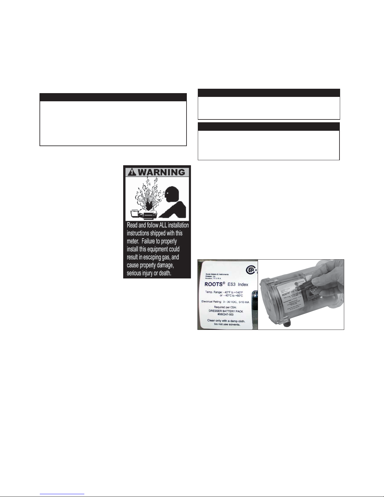
Figure 1 - Label on ES3
Electronic TC
Figure 2 - Swipe magnet across the
words “Roots ES3 Index” to change the
screen displays
2.1 LCD Screen Displays
1. The default screen is either Compensated Volume or
Non-Compensated Volume, depending on customer
configuration.
a. This parameter is the home/default screen.
b. After a time out of approximately 30 seconds, the
home screen always will appear.
2. Repeat the swiping motion of the magnet across
the words “Roots ES3 Index,” and the screens will
appear in sequential order as shown in Table 1.
Note: Using the Dresser MeterWare Software, the
screens are configured by checking and un-checking
the parameter to be displayed. Depending on the
ES3 configuration, some screens may not appear.
ROOTS* ES3 Electronic Temperature Compensator (TC)
Installation Procedures
WARNING
This equipment is designed to operate at temperatures
between -40° F to 140° F. Prior to going on-site for
installation or maintenance, make sure proper safety
equipment is worn before handling the equipment and
that you are properly dressed for the work site
environment temperatures.
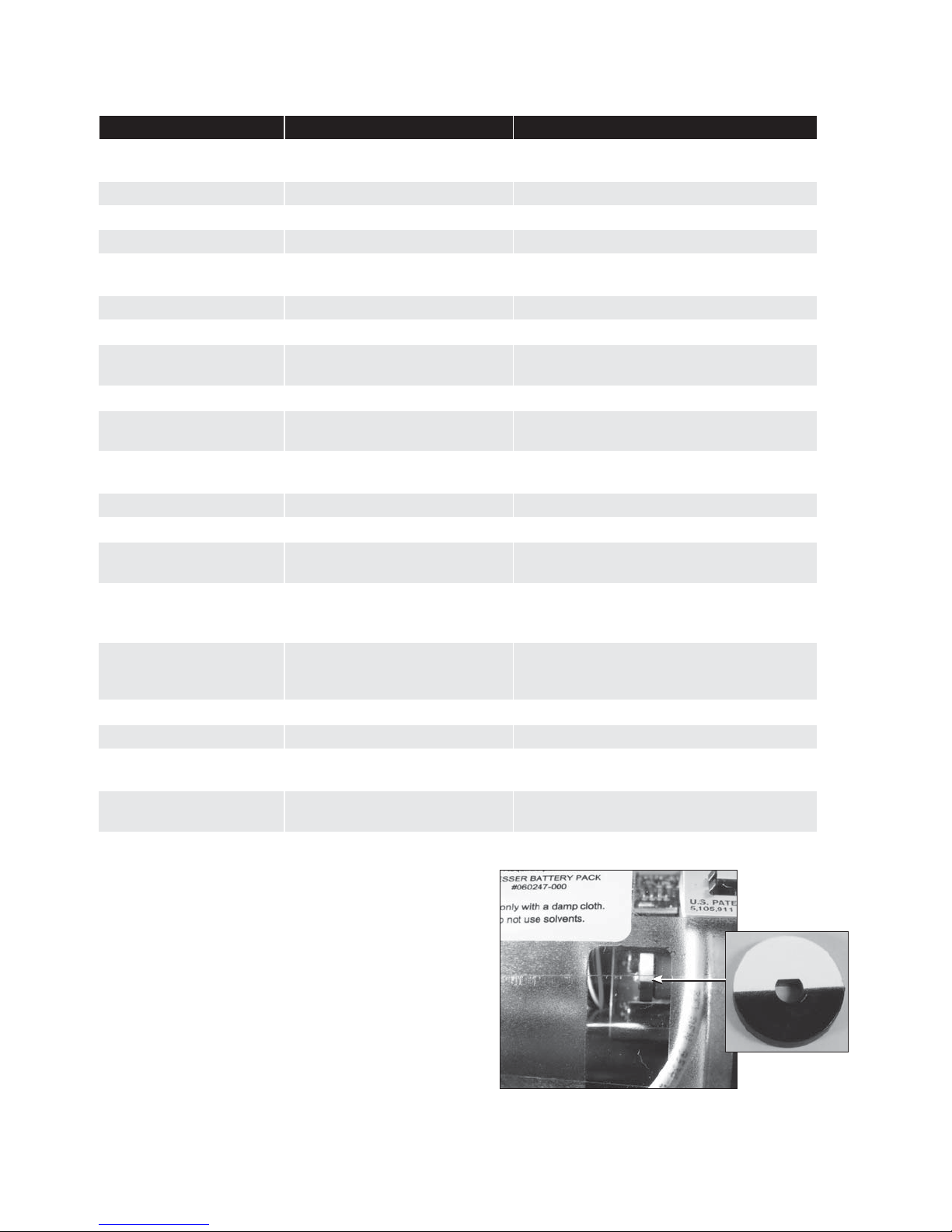
2. LCD Display
Scrolling through the screen displays and connecting
to the ES3 Electronic TC requires use of the magnet.
The magnet can be purchased as part of the
Communications Kit, P/N 060542-000 or as an individual
item, P/N 060541-000. Consult Factory for pricing.
Swipe the magnet across the words “Roots ES3 Index”
as shown in Figures 1 - 2.
Note: the magnet will not change screen displays if
swiped on another area of the label.
WARNING
If equipment is installed/serviced/maintained at
elevated heights, ensure proper safe site work practices
are in place to prevent fall and drop hazards.
WARNING
For installations in confined spaces, allow adequate
room to safely handle product and equipment without
causing bodily strain. Also verify proper ventilation is
in place to maintain a breathable atmosphere.

3
Displayed on Screen Represents Function
COMPENSATED VOLUME Compensated Volume Displays non-compensated volume which has
been corrected to standard conditions
NON-COMPENSATED VOLUME Non-compensated Volume Displays actual non-compensated volume
LINETEMP Line Temperature Displays live line temperature
FIXED P Fixed Line Temperature Displays the line pressure as entered by the user
FLOWRATE Flow Rate Displays uncorrected flow rate
(average of latest 30 seconds of captured data)
MTR INFO Meter Info Meter size and type
PROVE CV Compensated Prove Mode Allows for compensated volume accuracy testing
PROVE UV Non-compensated Prove Mode Allows for non-compensated volume
accuracy testing
BATTVOLT Battery Voltage Displays battery voltage
REM LIFE Remaining Life Calculated remaining battery life - shown in
months
FIRM REV Firmware Revisions Displays the firmware revision that is in the
ES3 at the present time
LCD TEST LCD Test Tests all display segments
BATTCHNG Change Battery Saves data to memory and resets clock
COMPFCTR Compensation Factor Displays the factor applied to non-compensated
volume in order to arrive at compensated volume
COMPENSATED RESIDUAL Compensated Residual
Shows extended compensated volume data
beyond the value shown in the compensated
volume screen
NON-COMPENSATED
RESIDUAL Non-compensated Residual
Shows extended non-compensated volume data
beyond the value shown in the non-compensated
volume screen
BASE T Base Temperature Displays base temperature as entered by the user
BASE P Base Pressure Displays base pressure as entered by the user
ATMOS Atmospheric Displays average atmospheric pressure as
entered by the user
NCVOLFLT Non-compensated volume under
fault
Displays non-compensated volume that has
accumulated since a fault occurred
3. Three to five seconds after the name of the value or
the parameter appears, the screen will switch to show
you the value of the selected parameter.
4. For an explanation of the data displays, refer to
Section 2 of the “IOM:ES3 Installation Operation and
Maintenance” manual. Consult Factory for a copy of
the manual.
3. RPM Wheel
A high-speed RPM wheel is visible to the left of the digital
display as shown in Figure 3.
The RPM wheel is tied directly to the meter impellers and
is used to verify gas flow through the meter.
Figure 3 - Movement of the RPM wheel
indicates impeller rotation
RPM wheel
Table 1 - Scrolling sequence for ES3 screen display

4
4. Wiring the Pulse Outputs
See Table 2 and Figure 4 for output pulse wiring for a
Circular Connector.
Output Name Connector Pin Pulse Type
Pulse Output 1 (+) PO1 (+) A Form A
Pulse Output 1 (-) PO1 (-) B
Drain (Drain) C —
Pulse Output 2 (+) PO2 (+) D Form A
Pulse Output 2 (-) PO2 (-) E
A
B
C
D
E
F
PO1 (+)
PO1 (-)
DRAIN PO2 (+)
PO2 (-)
Circular Connector
Figure 4 - Circular Connector Wiring
Table 2 - Circular Connector Wiring
NOTE:
The Circular mating connector is available with 5, 10 or
20 feet of cable. Contact Factory for price, part number
and availability.
To maintain compliance with CSA certification, use a
suitable Intrinsic Safety barrier for a Class 1 hazardous
area for groups A, B, C and D:
1. Do not exceed the following input values for the
barrier device:
a. Vi=8.2V b. Ii=1.5ma
2. The OUTPUT and power handling capability of a
barrier should not exceed:
a. Vout=30V b. Iout=50ma
Refer to Figure 5 for proper wiring in hazardous locations.
WARNING
Ensure properly licensed/trained professionals are used
to install equipment if installed in hazardous locations
containing explosive atmospheres. All local codes and
standards shall be maintained during installation.
WARNING
Products certified as intrinsically safe installations
shall be:
• Installed, put into service, used and maintained in
compliance with national and local regulations and
in accordance with the recommendations contained in
the relevant standards concerning potentially explosive
atmospheres.
• Used only in situations complying with the certification
conditions shown in this document and after verification
of their compatibility with the zone of intended use and
the permitted maximum ambient temperature.
• Installed, put into service and maintained by qualified
and competent professionals who have undergone
suitable training for instrumentation used in areas
with potentially explosive atmospheres.

5
JP2
JP4
A
B
CE
F
D
1
2
3
4
5
1
2
3
4
P1+
P1-
P2+
P2-
DRAIN
A
B
CE
F
D
ISOLATION AMPLIFIER
ISO-2
1
4
7
10
8
9
11
12
CIRCULAR
CONNECTOR
+1
-1
+2
-2
Open collector
independant output
channels. May be used as
PULL UP and or, PULL
down. FORM A and or,
FORM B respectively.
0 to 30VDC
0 to 50MADC
POWER SUPPLY INPUT FOR
ISOLATION
AMPLIFIERS.
20 to 250VAC
20 to 125VDC
3 watts
8.2V
10ma max
8.2V
10ma max
+
-
HAZARDOUS AREA NON HAZARDOUS AREA
TURCK
IM1-12Ex-T
(shown)
FORM A pulse
connections
transmitted to Isolation
Amplifiers.
Standard BLUE WIRE
Intrinsic safety
connections.
All intrinsically safe wiring
must be seperated from
any other safe zone wiring
by at least 2 inches in a
separate panduit.
Use TURCK IM1-12Ex-T single
channel, IM1-22 EX-R Dual channel
Isolation Amplifiers or, equivalent
which are capable of high speed
switching response.
HAZARDOUS AREA INSTALLATIONS IN
CANADA MUST BE INSTALLED IN
ACCORDANCE WITH THE CANADIAN
ELECTRICAL CODE (CEC) PART 1.
HAZARDOUS AREA INSTALLATIONS IN
THE UNITED STATES MUST BE
INSTALLED IN ACCORDANCE WITH THE
NATIONAL ELECTRIC CODE (NEC).
Either Normally open or Normally
closed output may be selected
with the, "NO/NC" ISO-AMP
switch in the front of these unts.
Pulse form may be selected per
requirements of the logging
system used.
ISOLATION AMPLIFIER
ISO-1
1
4
7
10
8
9
11
12
+1
-1
+2
-2
Open collector
independant output
channels. May be used as
PULL UP and or, PULL
down. FORM A and or,
FORM B respectively.
0 to 30VDC
0 to 50MADC
POWER SUPPLY INPUT FOR
ISOLATION
AMPLIFIERS.
20 to 250VAC
20 to 125VDC
3 watts
+
-
TURCK
IM1-12Ex-T
(shown)
PO-1(+)
PO-1(-)
PO-2(+)
PO-2(-)
ES3
INTRINSIC
SAFETY
GROUND
BUSS
Figure 5 - Wiring Diagram for hazardous locations.

5. Pulse Output Verification
Using the Dresser MeterWare software, the Corrector pulse output allocation is configured
in the Volume Configuration screen, as shown in Figure 6. Refer to this screen to verify
proper configuration. Refer to the MeterWare Manual for complete operating instructions.
Figure 6 - Volume Configuration screen in Dresser MeterWare software
To ensure pulse outputs are properly wired, the Dresser MeterWare software
has a test function available on the Advanced screen, as shown in Figure 7.
Figure 7 -Advanced screen in Dresser MeterWare software
After clicking “Test Pulse Outputs,” a screen appears as shown in Figure 8.
Click “Yes” to proceed with the pulse output test. For further information,
refer to the Dresser MeterWare Manual.
Figure 8- Send test Pulses screen in Dresser MeterWare software
GEA19694 IS:B3E
2.12
GE Oil & Gas
16240 Port Northwest Drive, Suite 100
Houston, TX 77041
P: +1 832.590.2303 Inside US P: 800.521.1114
F: +1 832.590.2494 Inside US F: 800.335.5224
Visit us online at:
www.ge.com/energy
2012 General Electric Company
All Rights Reserved
* Denotes a trademark of General Electric
Company
Table of contents
Other GE Measuring Instrument manuals

GE
GE Phasor XS User manual

GE
GE Moisture Image 1 Series User manual

GE
GE Phasor CV User manual

GE
GE SS-131ER User manual

GE
GE CB Watch 3 User manual

GE
GE MAC VU360 User manual

GE
GE RHM 03 User manual

GE
GE Kelman MULTITRANS User manual

GE
GE Krautkramer USM 35X User manual

GE
GE Bently Nevada 3300/16 User manual