GE Druck DPI 800 User manual

Druck DPI 800/802
Pressure indicator and
Pressure loop calibrator
User manual - K335
GE
Sensing
Advanced Test Equipment Rentals
www.atecorp.com 800-404-ATEC (2832)
®
E
s
t
a
b
l
i
s
h
e
d
1
9
8
1

K335 Issue 3
A1
A2 DPI 802/802P
A3
10 a, b, c
1
3
4
2
5
6
7
9
8
A 2
A 3
11
B1
12
10b
10a
10c
14
1513
20
21
22
24
1718
25
19 2616
23
B1
Customer service
Visit our web site: www.gesensing.com

[EN] English - 1
K335 Issue 3
Table of Contents
Introduction ......................................................................... 1
Safety ..................................................................................... 2
Marks and symbols on the instrument ................................. 2
To start .................................................................................. 2
Location of items ............................................................................ 2
Items on the display ...................................................................... 3
Prepare the instrument ................................................................ 3
Power on or off ................................................................................ 3
Set up the basic operation ......................................................... 3
Select a task (Measure) ................................................................ 4
Set up the settings ......................................................................... 4
Edit functions .................................................................................... 5
Operation .............................................................................. 5
Pressure connections ................................................................... 5
Communications port connections ........................................ 6
Measure pressure ........................................................................... 6
Leak test .............................................................................................. 6
Switch test .......................................................................................... 7
Transmitter calibration ................................................................ 7
mA measurements ........................................................................ 8
UPM Pressure measurements .................................................. 8
Error indications .............................................................................. 8
Maintenance ........................................................................ 9
Clean the unit ................................................................................... 9
Replace the batteries .................................................................... 9
Calibration ............................................................................ 9
Before you start ............................................................................... 9
Procedures (Pressure P1/P2) .................................................. 10
Procedures (mA input) ............................................................... 10
Procedures (IDOS UMM) ............................................................ 10
Specification data ............................................................ 11
General ............................................................................................. 11
Pressure measurement ............................................................ 11
Electrical connectors (A2) ......................................................... 12
Customer service ............................................... Back cover
© 2005 General Electric Company. All rights reserved.
Trademarks
All product names are trademarks of their respective companies.
Introduction
The DPI 800 Pressure Indicator and DPI 802 Pressure Loop
Calibrator are part of the Druck DPI 800 series of hand held
instruments.
The DPI 800 series uses Intelligent Digital Output Sensor
(IDOS) technology to give instant plug and play
functionality with a range of Universal Measurement
Modules (UMM). Example: the Universal Pressure Module
(UPM).
The DPI 800/802 include these functions:
Function DPI 800 DPI 802
Measure pressure *
* Refer to “Specification data”.
** Optional item
*** High range IDOS - Low range IDOS (if applicable)
Internal IDOS: P1 and/or P2**;
External IDOS: UPM**
Measure pressure
difference ***
Difference (∆) between: P1 and P2, or P1/P2
and a UPM
Leak Test Yes
Communications port IDOS or RS232
Language selection Yes
Pressure units 25 (Fixed)
Snapshot ** Up to 1000 displays with a date/time stamp
Measure mA No 0 - 55 mA
HART®resistor No Yes
V dc output No 24 V
Switch test No Yes
Other functions Hold, Maximum/Minimum/Average, Filter,
Tare, Scaled values, Backlight, Alarm

2- [EN] English K335 Issue 3
Safety
Before you use the instrument, make sure that you read
and understand all the related data. This includes: all local
safety procedures, the instructions for the UMM (if
applicable), and this publication.
WARNING
• Some liquid and gas mixtures are dangerous. This
includes mixtures that occur because of
contamination. Make sure that the instrument is
safe to use with the necessary media.
• It is dangerous to ignore the specified limits for the
instrument or to use the instrument when it is not in
its normal condition. Use the applicable protection
and obey all safety precautions.
• To prevent a dangerous release of pressure, isolate
and bleed the system before you disconnect a
pressure connection.
• Do not use the instrument in locations with explosive
gas, vapor or dust. There is a risk of an explosion.
• DPI 802/802P only. To prevent electrical shocks or
damage to the instrument, do not connect more
than 30V between the terminals, or between the
terminals and the ground (earth).
Before you start an operation or procedure in this
publication, make sure that you have the necessary skills
(if necessary, with qualifications from an approved training
establishment). Follow good engineering practice at all
times.
Safety - Marks and symbols on the instrument
The identification on each pressure connector includes the
type of thread (1/8 NPT, G1/8 ... ).
To start
To start - Location of items …
Complies with European
Union directives
Warning - refer to the
manual
Read the manual Battery
Ground (Earth) P1/P2 Identifies the pressure
range connector
ON/OFF
MWP
The maximum working pressure for the connector.
Example: 2 x FS (FS = Full scale pressure)
REFERENCE
The connector is a reference port for reference pressure only. Refer
to “Specification data”.
Item Description
1. ❍On or off button.
2. ■■Left-hand soft-key. Selects the function above it on
the display (Item 24). Example: Edit
3.
ESC
Moves back one menu level.
Leaves a menu option.
Cancels the changes to a value.
4. ▲
▼Increases or decreases a value.
Highlights a different item.
5. HOLD Holds the data on the display. To continue, press the
HOLD button again.
6. MENU
OK
Shows the Select Task menu.
Selects or accepts an item or value.
Selects [✓] or cancels [ ] a selection
7. ■■Right-hand soft-key. Selects the function above it on
the display (Item 24). Example: Settings
8. Display. Refer to A3
9. SENSOR/
PC
Communications port. Use to connect a Universal
Measurement Module (UMM) or a RS232 cable.
10. 10a. IDOS pressure connector with identification marks.
Refer to “Safety”.
10b. Label to identify the pressure range for the
associated IDOS pressure connector (P1/P2): Sealed
gage (sg), gage (g), absolute (a).
10c. PTFE vent filter or a reference port connector. Refer to
“Specification data”.
11. Connection point for some of the optional
accessories. Refer to the datasheet.
12. Battery compartment. Refer to B1.
13., 14., 15. DPI 802/802P only. Terminals to measure current, to
supply 24V source, and to do switch tests.
A1 A2

[EN] English - 3
K335 Issue 3
To start - Items on the display
To start - Prepare the instrument
Before you use the instrument for the first time:
• Make sure that there is no damage to the instrument,
and that there are no missing items.
• Remove the plastic film that protects the display. Use
the tag (◗) in the top right-hand corner.
• Install the batteries (refer to B1). Then re-attach the
cover.
To start - Power on or off
To turn the instrument on or off, press ❍(A1 - item [1]). The
instrument does a self test and then shows the applicable
data.
When the power is off, the last set of configuration options
stays in memory. Refer to “Maintenance”.
To start - Set up the basic operation
Use the Set Up menu to set up the basic operation of the
instrument.
If there is additional data for a menu option, select
Settings (■■) to see the values that are set up. If
necessary, adjust the values.
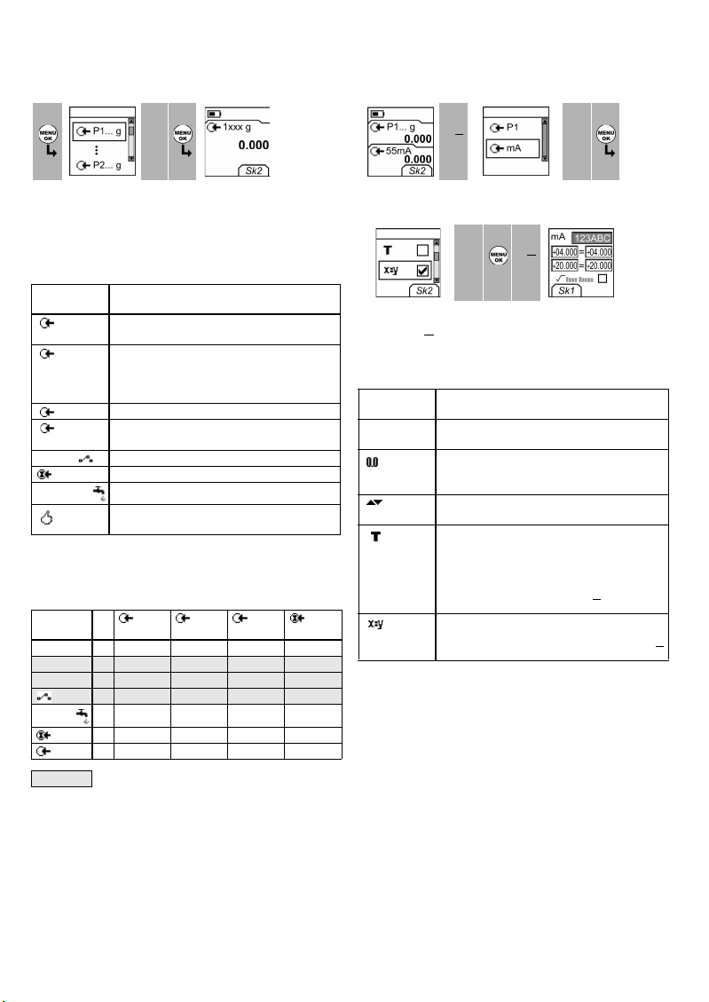
Table 1: Menu options - Set Up
Item Description
16. DPI 802/802P only. Task indication for the switch test.
= switch closed = switch open
Task indication for the leak test.
Refer to: Select Task (Table 2/3)
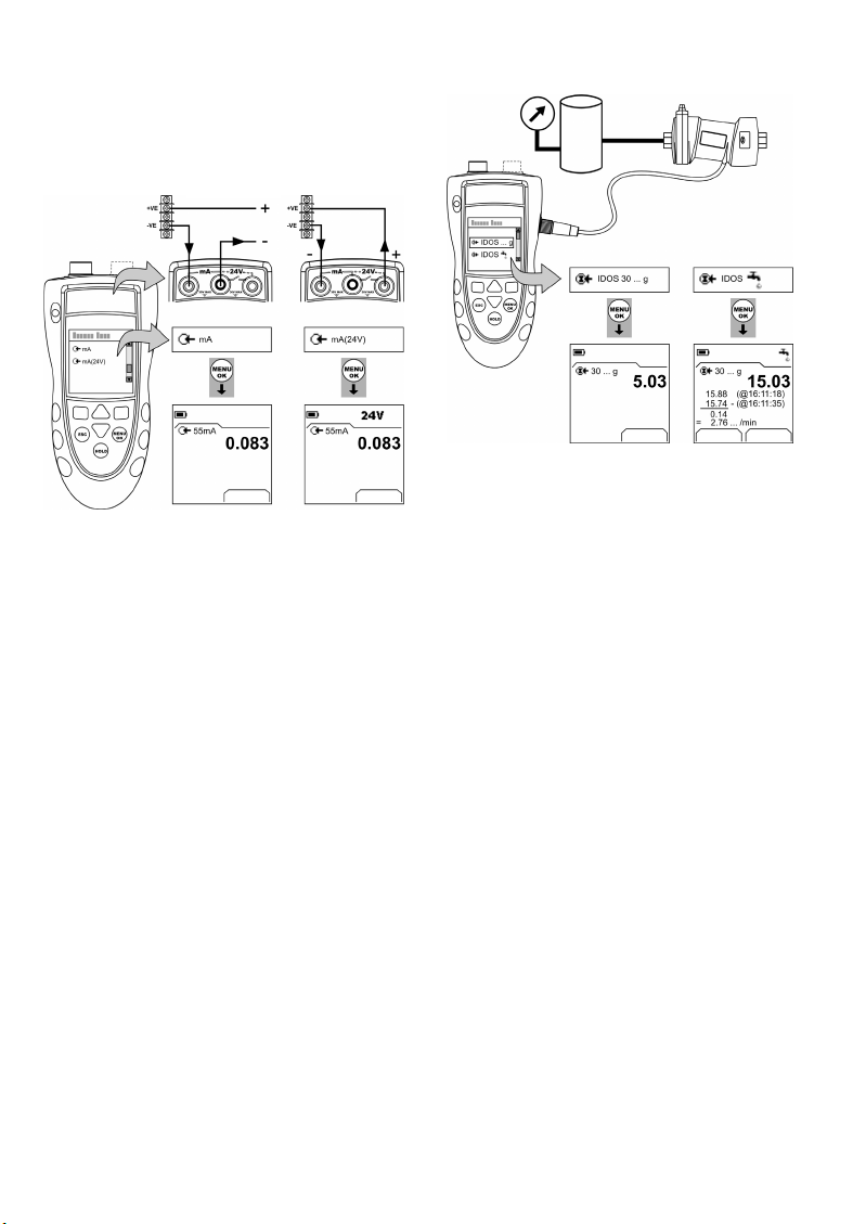
17. DPI 802/802P only. The loop power supply is on.
Refer to: Select Task (Table 2/3)
18. The measured value satisfies one of the alarm
conditions. Refer to: Settings (Table 4)
19. The data on the display is on hold. To continue, press
the HOLD button again.
20. Shows the battery level: 0 ... 100%.
21. Identifies the type of data and the measurement
range.
= Input = IDOS input
Refer to: Select Task (Table 2/3)
22. ... 23. Identifies the settings applied to the input.
Refer to: Settings (Table 4)
22. xxxx g The units and the type of sensor (If applicable)
OR a specified scale (x:y).
23. Shows the settings applied to the measured value (If
applicable).
= Filter
= Tare
= Maximum
= Average
= Minimum
24. A soft-key function. To select an available function,
press the soft-key below it. Example:
= Move left = Move right
25. The measured value or values applicable to the task
selection.
26. The Edit display to set up text labels ( ≤6 characters):
x:y Scaling (Table 4).
OK = Accept the new text label
Shift = Change the keys: 123ABC or -_+abc
= Add a space
BS = Back space (Delete character)
A3
1Menu:
Select Task 23 Menu:
Set Up 45
▲
▼▲
▼
(Table 2) (Table 1) [✓]/[ ]
Options
(If applicable)
Description
DPI 802/802P only. To add a series resistor into the
mA circuit. You can then use this instrument
together with a HART®communicator to set up
and calibrate HART®devices.
To select and set up the backlight facility + timer.
Additional data: Select Settings (■■)
To select and set up the power off facility + timer.
Additional data: Select Settings (■■)
To show the battery level (%).
To set the display contrast (%).
▲ Increases %, ▼ decreases %
To set the time + date. The calibration facility uses
the date to give service and calibration messages.
To set the language option.
To calibrate the instrument.
Additional data: Refer to “Calibration”.
To select and show the applicable status data
(Software Build, Calibration Due date, Serial
Number, IDOS Information).

4- [EN] English K335 Issue 3
To start - Select a task (Measure)
When the instrument is set up (Table 1), use the Select Task
menu to select the applicable task.
In Table 2/3, P1 and P2 are internal sensors, and IDOS is a
Universal Measurement Module (UMM). If you attach a
UMM to the communications port (A1 - item [9]), the Select
Task menu shows the applicable IDOS options.
Table 2: Menu options - Select Task
Table 3 shows all the one and two function operations that
are available. If you attach a UMM, you can only use the
options that include IDOS.
Table 3: Permitted 1 and 2 function operations
To start - Set up the settings
When the task is set up (Table 2/3), use the Settings menu
to adjust the measurement operation.
If there is additional data for a menu option, select
Settings (■■) to see the values that are set up. If
necessary, adjust the values. Refer to “Edit functions”
Table 4: (Part of table) Menu options - Settings
1Menu:
Select Task 23 Display:
Task 1xxx g
▲
▼
(Table 2/3) Sk2 = Settings
Options
(If applicable)
Description
(* Optional item)
P... An input measurement task (P1, P2*). The task
includes the pressure range for the sensor.
∆P... An input measurement task to measure the
pressure difference (∆) between: P1 and P2*, or
P1/P2* and a UPM*.
∆P = High range IDOS - Low range IDOS
mA DPI 802/802P only. A mA measurement task.
mA(24V) DPI 802/802P only. A mA measurement task + the
loop power supply is on.
DPI 802/802P only. A switch test.
IDOS UMM only. An IDOS measurement task.
Pressure options only. A leak test.
To set up the way the instrument works.
Additional data: Refer to: Set Up (Table 1).
Function
P1 P2
∆P...
(Table 2) IDOS
(1) (1) (1) (1)
mA (1) (2) (2) (2) (2)
mA(24V) (1) (2) (2) (2) (2)
x(2) (2) (2) (2)
x(2) (2) x (2)
IDOS (1) (2) (2) x x
P2(1)(2)xx(2)
= DPI 802/802P only
Display: Task
P1 + mA 1Settings selection
(If applicable) 23
■■▲
▼
Sk2 = Settings
Menu:
Settings 456 Settings
x:y
▲
▼■■
(Table 4) [✓]/[ ] Sk1 = Edit
Options
(If applicable)
Description
... Units To select one of the fixed units of measurement
(psi, mbar ... ).
Gage sensors or sensors with differential
operation (P1, P2, IDOS). A zero correction that
makes the instrument read zero at local pressure.
To include maximum, minimum and average
values for the measurement task.
To select and set up a tare value for the
measurement task (a specified value or the
reading on the display).
The instrument subtracts a positive tare value, and
adds a negative tare value.
Additional data: Select Settings (■■)
To select and set up a scale of values: One local
scale for each measurement task (Maximum: 5).
Additional data (Example 1/2): Select Settings (■■)

[EN] English - 5
K335 Issue 3
Table 4: (Part of table) Menu options - Settings
To start - Edit functions
Example 1) Set up a label for x:y Scaling = %.
Example 2) Set up values for x:y Scaling = 0 to 100%.
Operation
This section gives examples of how to connect and use the
instrument. Before you start:
• Read and understand the “Safety” section.
• Do not use a damaged instrument.
Operation - Pressure connections
CAUTION: To prevent damage, do not apply torque to
the body of the instrument. If available, use the flat
faces on the pressure connector to hold the instrument
in position.
Use an applicable method to seal the pressure
connections, and then tighten to the applicable torque
(Figure 1 and Table 5).
Note: If the instrument uses G1/8 connections, and the
pressure is
≥
1500 psi (100 bar), connection method (b) is
mandatory.
Figure 1: Connection methods
Table 5: Key to figure 1
Options
(If applicable)
Description
To select and set up the filter values to give a
smoother output for the measurement task:
Band as a % of full scale (FS). The filter
compares each new value with the previous
value. If the new value is outside the band, it
is not filtered.
Low pass filter time constant in seconds.
Increase the value to increase the damping
factor.
Additional data: Select Settings (■■)
To select and set up the alarm values for the
measurement task (maximum and minimum).
Additional data: Select Settings (■■)
Leak Test only. To set an applicable period for the
leak test (Hours:Minutes:Seconds).
Settings
x:y 1Edit 2Edit 3
■■▲
▼
■■
Sk1 = Edit A3 - item [26]
Edit ... Edit 45
%_
▲
▼
■■
A3 - item [26]
Settings
x:y 1Settings
x:y 2Edit 34
▲
▼
■■
▲
▼
■■
Sk1 = Edit
= Flow scaling (mA, pressure only)
Shift
OK
Item Description
1 Process connector. Maximum torque:
1/8 NPT: 26 lbf.ft (35 Nm)
G1/8: 18.4 lbf.ft (25 Nm)
2 Applicable instrument pressure connector (Table 10)
3 (1/8 NPT only) Thread with an applicable sealant
4 (G1/8 only) Applicable bonded seal
5 Reference port connector: M5 or 10-32 UNF (Table 10)
Maximum torque: 1.5 lbf.ft (2 Nm)
12 1 2
12
3
2
4
4
5
c) G1/8 connections:
Pressure
<
1500 psi
(100 bar)
a) 1/8 NPT
connections
b) G1/8 connections:
Pressure
≥
1500 psi (100 bar)
d) M5 or 10-32 UNF
connections:
Refer to “Table 10”

6- [EN] English K335 Issue 3
Operation - Communications port connections
Use the communications port (A1 - item [9]) to attach an
IDOS Universal Measurement Module (UMM).
When you attach the cable from a UMM (Figure 8), the
instrument automatically changes the menus to give you
all the applicable options (Table 2/3).
Operation - Measure pressure
To measure the pressure or the pressure difference (if
there are two IDOS pressure ranges).
1. Connect the instrument (Figure 2) and, if necessary,
adjust the Set Up (Table 1).
2. Select an applicable pressure task from Select Task
(Table 2/3) and, if necessary, adjust the Settings
(Table 4).
3. If necessary, do a zero correction (Table 4).
4. Before you disconnect the instrument, isolate and
bleed the system.
Figure 2: Example configuration - Measure pressure
The examples in Figure 2 show:
• how to measure one or two pressures in a system
• how to measure pressure difference
Note:
∆
P = High range IDOS - Low range IDOS. If
Pressure (p2) > Pressure (p1), the result is negative.
Operation - Leak test
To do a leak test on a pressure system:
1. Connect the instrument (Figure 3) and, if necessary,
adjust the Set Up (Table 1).
2. Select an applicable leak test from Select Task
(Table 2/3) and, if necessary, adjust the Settings
(Table 4).
3. Set the period for the leak test (Table 4).
4. If necessary, do a zero correction (Table 4).
5. To start the leak test, select Start (■■). When the test is
finished, the instrument calculates the leak rate in the
applicable units/minute.
6. Before you disconnect the instrument, isolate and
bleed the system.
Figure 3: Example configuration - Leak test
Settin
p1
Settings Settings
a) P1 and/
or P2
b) P1 - P2
p2
p1
p2
P2P1
Start Settings

[EN] English - 7
K335 Issue 3
Operation - Switch test
DPI 802/802P only. To do tests on a pressure switch:
1. Connect the instrument (Figure 4) and, if necessary,
adjust the Set Up (Table 1).
2. Select the applicable switch test from Select Task
(Table 2/3) and, if necessary, adjust the Settings
(Table 4). The display shows the switch condition (open
or closed) in the top right-hand corner.
3. If necessary, do a zero correction (Table 4).
4. Slowly apply pressure to the system until the switch
changes condition (open or closed).
5. Slowly release the pressure until the switch changes
condition again. The display shows the pressure values
to open and close the switch.
6. To do the test again, press ESC to reset the values.
7. Before you disconnect the instrument, isolate and
bleed the system.
Figure 4: Example configuration - Switch test
Operation - Transmitter calibration
DPI 802/802P only. To calibrate a transmitter:
1. Connect the instrument (Figure 5 or Figure 6) and, if
necessary, adjust the Set Up (Table 1).
2. Select the applicable calibration task from Select Task
(Table 2/3) and, if necessary, adjust the Settings
(Table 4).
3. If necessary, do a zero correction (Table 4).
4. For each calibration point, apply an applicable
pressure and wait for the pressure system to stabilize.
5. Before you disconnect the instrument, isolate and
bleed the system.
Figure 5: Example configuration - Transmitter calibration
with external loop power
Figure 6: Example configuration - Transmitter calibration
with internal loop power
Settings
Settings
Maximum: 30V
Settings

8- [EN] English K335 Issue 3
Operation - mA measurements
DPI 802/802P only. To measure a current:
1. Connect the instrument (Figure 7) and, if necessary,
adjust the Set Up (Table 1).
2. Select the applicable mA task from Select Task
(Table 2/3) and, if necessary, adjust the Settings
(Table 4).
Figure 7: Example configuration - mA measurement
Operation - UPM Pressure measurements
Read all the instructions supplied with the UPM and then
use the specified procedures to connect it (Figure 8).
Figure 8: Example configuration - Pressure measurement
with a UPM
When the connections are complete, make the necessary
IDOS selections (Table 2/3). Then use the same procedures
as specified for the P1/P2 connections.
If you re-attach a UPM, the instrument uses the same
measurement units that you used before. The instrument
keeps a record for the last 10 modules.
Operation - Error indications
If the display shows <<<< or >>>> :
• Make sure that the range is correct.
• Make sure that all the related equipment and
connections are serviceable.
Settings Settings
a) with external loop
power
b) with internal loop
power
Maximum: 30V
Settings
a) Pressure b) Leak test
Start Settings

[EN] English - 9
K335 Issue 3
Maintenance
This section gives procedures to maintain the unit in a
good condition. You must return the unit to the supplier for
all repairs.
Maintenance - Clean the unit
Clean the case with a moist, lint-free cloth and a weak
detergent. Do not use solvents or abrasive materials.
Maintenance - Replace the batteries
To replace the batteries, refer to B1. Then re-attach the
cover.
Make sure that the time and date are correct. The
calibration facility uses the date to give service and
calibration messages.
All the other configuration options stay in memory.
Calibration
Note: GE can provide a calibration service that is traceable
to international standards.
We recommend that you return the instrument to the
manufacturer or an approved service agent for
calibration.
If you use an alternative calibration facility, make sure that
it uses these standards.
Calibration - Before you start
To do an accurate calibration, you must have:
• the calibration equipment specified in Table 6.
• a stable temperature environment: 70 ± 2°F (21 ± 1°C)
Table 6: Calibration equipment
Before you start the calibration, make sure that the time
and date on the instrument are correct (Table 1).
Selection sequence:
➤
Select Task (Table 2)
➤
Set Up (Table 1)
➤
Calibration
➤
Table 7: Calibration options
When you select a channel, the display shows the
applicable instructions to complete the calibration.
When the calibration is complete, select Calibration Due
and set the new calibration date for the instrument.
Function Calibration equipment
Pressure An applicable pressure standard
(primary or secondary) with a total
uncertainty of 0.01% reading or
better.
mA mA calibrator.
Accuracy: Refer to Table 9.
B1
1Display: Enter
Calibration PIN 23 Menu:
Select Channel 45
▲
▼
+
■■
▲
▼
Factory PIN = 4321 (Table 7)
Options
(If applicable)
Description
(* Optional item)
P... To calibrate the specified IDOS pressure input
(P1 or P2*).
IDOS ... UMM only. To calibrate the specified IDOS UMM.
Refer to the user manual for the IDOS UMM.
mA DPI 802/802P only. To calibrate the mA input.
Calibration Due: To set the date of the next
calibration for the instrument.
After the specified calibration date, there is a
warning message. There is a selection box to stop
the warning.
To change the calibration PIN (Personal
Identification Number).

10 - [EN] English K335 Issue 3
Calibration - Procedures (Pressure P1/P2)
1. Connect the instrument to the pressure standard
(Figure 2).
2. Let the equipment get to a stable temperature
(minimum: 30 minutes since the last power on).
3. Use the calibration menu (Table 7) to do a two-point
calibration (Zero and +FS) or a three-point calibration
(-FS, Zero and +FS). Refer to Table 8. The display shows
the applicable instructions to complete the calibration.
Table 8: Calibration pressures
4. To make sure that the calibration is correct, select the
applicable pressure task (Table 2) and apply these
pressure values:
• Ranges g/d or sg: 0, 20, 40, 60, 80, 100 (%FS)
Then: Go back to 0 in the same steps.
Then (three-point calibration only):
-20, -40, -60, -80, -100 (%FS)
Then: Go back to 0 in the same steps.
• Ranges a: 0, 20, 40, 60, 80, 100 (%FS)
Then: Go back to 0 in the same steps.
5. Make sure that the error is in the specified limits:
• Standard accuracy:
The specified accuracy (refer to “Specification data”)
includes an allowance for temperature changes, reading
stability for one year, and the uncertainty of the standard
used for calibration.
In step 4, make sure that the error between the applied
pressure and the reading on the unit is not more than
0.015% FS.
• Premier precision:
The specified precision (refer to “Specification data”)
includes an allowance for temperature changes and the
uncertainty of the standard used for calibration.
In step 4, make sure that the error between the applied
pressure and the reading on the unit is not more than the
specified value for Premier precision.
Calibration - Procedures (mA input)
1. DPI 802/802P only. Connect the instrument to the
calibration equipment (Figure 7).
2. Let the equipment get to a stable temperature
(minimum: 5 minutes since the last power on).
3. Use the calibration menu (Table 7) to do a three-point
calibration (-FS, Zero and +FS). The display shows the
applicable instructions to complete the calibration.
4. To make sure that the calibration is correct, select the
applicable mA task (Table 2) and apply these values:
• mA: -55, -40, -24, -18, -12, -6, 0 (short circuit)
Then: 0, 6, 12, 18, 24, 40, 55.
5. Make sure that the error is in the specified limits
(Table 9).
Table 9: mA input error limits
Calibration - Procedures (IDOS UMM)
Refer to the user manual for the IDOS UMM.
When the calibration is complete, the instrument
automatically sets a new calibration date in the UMM.
Ranges: g/d Nominal applied pressure
psi (mbar)
-FS † Zero +FS
≤10.0 psi (700 mbar) -FS 0 +FS
> 10.0 psi (700 mbar) -13.1 (-900) 0 +FS
† For a three-point calibration, do not apply more than -90% of
the specified FS for the unit.
Ranges: a Nominal applied pressure
psi (mbar)
Zero +FS
5.00 psi (350 mbar) < 0.02 (1.0) +FS
30.0 psi (2 bar) < 0.07 (5.0) +FS
100.0 psi (7 bar) < 0.29 (20.0) +FS
300.0 psi (20 bar) < 0.73 (50.0) +FS
Ranges: sg Nominal applied pressure
Zero +FS
≥5000 psi (350 bar) Use atmospheric
pressure as zero.
+FS
Applied
mA
Calibrator
error
(mA)
Permitted
DPI 800/802 error
(mA)
±55 0.0022 0.005
±40 0.0018 0.004
±24 0.0014 0.003
±18 0.0004 0.003
±12 0.0003 0.002
±6 0.0002 0.002
0 (Short circuit) - 0.001

[EN] English - 11
K335 Issue 3
Specification data
All accuracy statements are for one year.
Specification - General
Specification - Pressure measurement
The % full scale (FS) statements for Standard accuracy and
Premier precision are only applicable if there is a regular
zero correction by the IDOS instrument.
Languages English [Default]
Operating
temperature
14 … 122°F (-10 … 50°C)
Storage
temperature
-4 … 158°F (-20 … 70°C)
Humidity 0 to 90% without condensation
(Def Stan 66-31, 8.6 cat III)
Shock/Vibration BS EN 61010:2001; Def Stan 66-31, 8.4 cat III
EMC BS EN 61326-1:1998 + A2:2001
Safety Electrical - BS EN 61010:2001;
Pressure Equipment Directive - Class: Sound
Engineering Practice (SEP); CE Marked
Size (L: W: H) Maximum: 7.5 x 3.3 x 2.0 in
(190 x 85 x 50 mm)
Weight 19 oz (530 g)
Power supply 3 x AA alkaline batteries
Duration
(Measure)
P1: ≈ 50 hours
P1 + mA: ≈ 5 hours (24 V Source at 12 mA)
Ranges: Gage and differential operation (g/d),
sealed gage (sg), absolute (a)
Type Standard Accuracy *
% FS
Premier Precision †
% FS
Notes
+/- psi: 0.36 (+/- mbar: 25) g/d 0.1 0.03 1/2
+/- psi: 1, 3, 5, 10 (+/- mbar: 70, 200, 350, 700) g/d 0.075 0.03 1/2
psi: -15 to [15 or 30]
(bar: -1 to [1 or 2])
g/d 0.05 0.01 1/2
psi: -15 to [50, 100, 150, or 300]
(bar: -1 to [3.5, 7, 10, or 20])
g/d 0.05 0.01 1/3
psi: 500, 1000, 1500, 2000, 3000
(bar: 35, 70, 100, 135, 200)
g/d 0.05 0.01 1/3
psi: 5 (mbar: 350) a 0.1 - 2
psi: 30 (bar: 2) a 0.075 - 2
psi: 100, 300 (bar: 7, 20) a 0.075 - 3
psi: 5000, 10000 (bar: 350, 700) sg 0.05 - 3
* Standard accuracy is for 32 … 122°F (0 … 50°C);
Stability: 1 year
† Premier precision is for 65 … 82°F (18 … 28°C);
Stability:
≤
10 psi (700 mbar) = 0.02% of reading/Year
Stability:
>
10 psi (700 mbar) = 0.01% of reading/Year
Premier precision for 41 … 113°F (5 … 45°C):
≤
10 psi (700 mbar): 0.075% FS
>
10 psi (700 mbar): 0.014% FS
Notes:
1. Reference port media: Non-corrosive, dry gas
2. + port media: Non-corrosive, non-conductive liquid or
Non-corrosive, dry gas
3. + port media: Media applicable to stainless steel

12 - [EN] English K335 Issue 3
Table 10: DPI 800 series pressure connections
Table 11: Maximum pressure (+ port)
Table 12: Maximum pressure (Reference port)
Specification - Electrical connectors (A2)
Ranges Pressure connections
(One IDOS range)
Pressure connections
(Two IDOS ranges)
g/d: ≤30 psi g (2 bar g)
Standard or Premier
1/8 NPT female (+ port) + 1/8 NPT female reference
port OR
G1/8 female (+ port) + G1/8 female reference port
Two 1/8 NPT female (+ port) + 10-32 UNF reference
port OR
Two G1/8 female (+ port) + M5 reference port
g/d: >30 psi g (2 bar g)
Standard only
1/8 NPT female (+ port) OR
G1/8 female (+ port)
Two 1/8 NPT female (+ port) OR
Two G1/8 female (+ port)
g/d: >30 psi g (2 bar g)
Premier only
1/8 NPT female (+ port) + 10-32 UNF reference port OR
G1/8 female (+ port) + M5 reference port
Two 1/8 NPT female (+ port) + 10-32 UNF reference
port OR
Two G1/8 female (+ port) + M5 reference port
sg or a: all ranges G1/8 female (+ port) OR
1/8 NPT female (+ port)
Two 1/8 NPT female (+ port) OR
Two G1/8 female (+ port)
Ranges: g/d, sg, a MWP Maximum transient /
intermittent pressure
≤5 psi (350 mbar) 2 x FS 4 x FS
>5 psi (350 mbar) 1.2 x FS 2 x FS
Ranges: g/d only MWP
≤5 psi (350 mbar) 2 x FS
10 to 15 psi
(700 mbar to 1 bar)
1.2 x FS
≥30 psi (2 bar) 30 psi (2 bar)
Range (Measure) 0 to ±55 mA
Accuracy 0.02% of reading + 3 counts
Temperature coefficient
14 … 50°F, 86 … 122°F
(-10 … 10°C, 30 … 50°C)
0.0011% FS / °F
(0.002% FS / °C)
Switch detection Open and closed. 2 mA current.
Loop power output 24 V ± 10%
HART®resistor 250 Ω (menu selection)
Connectors (A2) Three 0.16 in (4 mm) sockets
This manual suits for next models
1
Table of contents
Other GE Measuring Instrument manuals
Popular Measuring Instrument manuals by other brands

NUCLEONIX SYSTEMS PRIVATE LIMITED
NUCLEONIX SYSTEMS PRIVATE LIMITED RM704 instruction manual

Bacharach
Bacharach MGS-250 installation guide

GARANT
GARANT XCONTROL user guide

TSI Incorporated
TSI Incorporated 4140 Operation and service manual

Triplett
Triplett CableRater instruction manual

Reely
Reely 1082712 operating instructions