GE JGP628 Technical manual

planning guide
Featuring GE Profile™ and GE®
36" and 30" telescopic downdraft systems

36" and 30" cooktop/downdraft system counter installation
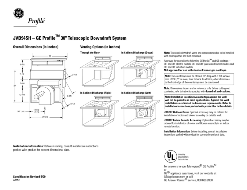
JVB98SH/94SH, JVB67H/37H
Note: The countertop must be at least 26" deep with a flat surface area
of 23-1/2" or more, front to back. In addition, other clearances to the
front edge must be considered.
Note: JP950S, JP940S, JP930S, JP910S, JGP940S require 23-5/8" flat
surface area.
Note: See specific cutout illustrations with your cooktop model to
determine requirements.
Note: A countertop with a raised or a rolled front edge may not allow
enough flat area for installation.
Planning Installation Preparing Cutout
“A” Fig. 1 “B” Fig. 1 “B” & Vent Fig. 1 “C” Fig. 2 “D” Fig. 2 “E” Fig. 2 “F” Fig. 2
Overall Min. required
Surface Depth setback from
Cooktop front edge Countertop Combined Combined
Cooktop Cooktop Depth + Vent to front edge inside cabinet Cutout Cutout
36" Models Overall Width Overall Depth Cover Depth of cutout clearance Width Depth
Electric
JP980S/JP960S/JP970S 36-1/8" 21-1/4" 25 -1/4" 2-1/2"* 22-11/16" 33-7/8" 21-7/8"
JP980/JP960/JP970 36" 21-3/16" 24-5/8" 2-1/2"* 22-11/16" 33-7/8" 21-3/4"
JP655S 36-1/8" 20-7/16"
JP655 36" 20-3/8"
JP626 35-1/2" 21" 25-1/4" 2-1/2" 22-11/16" 33-7/8" 21-7/8"
Gas
JGP975/JGP963/
JGP637/JGP630/JGP628 36" 21" 25-1/4" 2-1/2" 22-11/16" 33-7/8" 21-7/8"
JGP970S 36" 21-1/4" 24-11/16" 2-1/2"* 22-11/16" 33-7/8" 21-3/4"
JGP970 36" 21-3/16" 24-11/16" 2-1/2"* 22-11/16" 33-7/8" 21-3/4"
30" Models
Electric
JP950S/JP940S/
JP930S/JP910S 29-7/8" 21-1/2" 25-3/4" 2-1/2"* 22-7/16" 28-1/2" 22-3/8"
JP950/JP940/
JP930/JP910 29-3/4" 21-7/16" 25-1/8" 2-1/2"* 22-7/16" 28-1/2" 22-1/4"
JP355 29-3/4" 20-7/8" 25-1/2" 2-1/2" 22-7/16" 28-1/2" 22-3/8"
JP340 29-3/4" 20-7/8" 25-1/2" 2-1/2" 22-7/16" 28-1/2" 22-3/8"
Gas
JGP933/JGP337/
JGP330/JGP328 30" 21" 25-1/4" 2-1/2" 22-7/16" 28-1/2" 22-3/8"
JGP940S 29-3/4" 21-3/8" 25-1/4" 2-1/2"* 22-7/16" 28-1/2" 22-1/4"
JGP940 29-3/4" 21-7/16" 25-1/4" 2-1/2"* 22-7/16" 28-1/2" 22-1/4"
JGP321 30-1/4" 21-1/4" 25-1/2" 3-1/4" 22-7/16" 28-1/2" 22-1/4"
* Raised edge bull nose countertops may require up to 3/8" additional clearance to prevent
interference with curved front.
Flat Surface Area
No Gas or Electric
Service Inside
Shaded Area
Island or
Peninsula*
G
D
H
J
I
D
1-7/8"
7"
2-1/8"*
Vent
F
E
C
Island or
Peninsula*
C
L
C
D
H
F
E
G
Cooktop
Minimum
Inside Cabinet
Clearance
Fig. 2
Overall Cutout Dimensions
No Gas or Electric
Service Inside
Shaded Area
Island or
Peninsula*
*These vents are recommended
for island installation. Against the
wall installations are limited due
to dimension requirements. Refer
to installation instructions, packed
with product, for further details.
K = 34" For 36" Models
28-1/2" For 30" Models
J = 29-1/2
J= 32-1/4"
I= 29-1/2"
E
F
K
J
** Includes 1/8" required
gap between cooktop
and vent trim.
Vent
D
2-1/4"
12-3/8"
Max.
6-3/8"
2-1/8"*
14-3/4"
27"
8-1/2" Lift
36"/30"
36"/30"
Vent
Dim. D to
Cutout
2-1/4
6-3/8
24-3/4
27
3/4" Thick
Support Rail
Cooktop
Downdraft Vent
7
12-3/8
6" Dia. or 3-1/4" x 10"
Rectangular Duct required.
24"
A
B
No Gas or Electric
Service Inside
Shaded Area
G= 34" for 36" models
33-7/8" for 30" models
H= 27-1/2"
No Gas or Electric
Service Inside
Shaded Area
Island or
Peninsula*
G
D
H
J
I
D
1-7/8"
7"
2-1/8"*
Vent
F
E
C
Island or
Peninsula*
C
L
C
D
H
F
E
G
Cooktop
Minimum
Inside Cabinet
Clearance
Fig. 2
Overall Cutout Dimensions
No Gas or Electric
Service Inside
Shaded Area
Island or
Peninsula*
*These vents are recommended
for island installation. Against the
wall installations are limited due
to dimension requirements. Refer
to installation instructions, packed
with product, for further details.
K = 34" For 36" Models
28-1/2" For 30" Models
J = 29-1/2
J= 32-1/4"
I= 29-1/2"
E
F
K
J
** Includes 1/8" required
gap between cooktop
and vent trim.
Vent
D
2-1/4"
12-3/8"
Max.
6-3/8"
2-1/8"*
14-3/4"
27"
8-1/2" Lift
36"/30"
36"/30"
Vent
Dim. D to
Cutout
2-1/4
6-3/8
24-3/4
27
3/4" Thick
Support Rail
Cooktop
Downdraft Vent
7
12-3/8
6" Dia. or 3-1/4" x 10"
Rectangular Duct required.
24"
A
B
No Gas or Electric
Service Inside
Shaded Area
G= 34" for 36" models
33-7/8" for 30" models
H= 27-1/2"
Required to
maintain U.L. or
AGA approvals.
* Includes 1/8" required gap
between cooktop and vent trim.

Fig. 1
Overall cooktop dimensions
It is recommended that gas and/or electrical
service for cooktop and downdraft should not be
placed on the back wall because it may interfere
with the downdraft plenum.
* These vents are recommended for island installation. Against the wall installations are
limited due to dimension requirements. Refer to installation instructions, packed with product,
for further details.
No Gas or Electric
Service Inside
Shaded Area
Island or
Peninsula*
G
D
H
J
I
D
1-7/8"
7"
2-1/8"*
Vent
F
E
C
Island or
Peninsula*
C
L
C
D
H
F
E
G
Cooktop
Minimum
Inside Cabinet
Clearance
Fig. 2
Overall Cutout Dimensions
No Gas or Electric
Service Inside
Shaded Area
Island or
Peninsula*
*These vents are recommended
for island installation. Against the
wall installations are limited due
to dimension requirements. Refer
to installation instructions, packed
with product, for further details.
K = 34" For 36" Models
28-1/2" For 30" Models
J = 29-1/2
J= 32-1/4"
I= 29-1/2"
E
F
K
J
** Includes 1/8" required
gap between cooktop
and vent trim.
Vent
D
2-1/4"
12-3/8"
Max.
6-3/8"
2-1/8"*
14-3/4"
27"
8-1/2" Lift
36"/30"
36"/30"
Vent
Dim. D to
Cutout
2-1/4
6-3/8
24-3/4
27
3/4" Thick
Support Rail
Cooktop
Downdraft Vent
7
12-3/8
6" Dia. or 3-1/4" x 10"
Rectangular Duct required.
24"
A
B
No Gas or Electric
Service Inside
Shaded Area
G= 34" for 36" models
33-7/8" for 30" models
H= 27-1/2"
No Gas or Electric
Service Inside
Shaded Area
Island or
Peninsula*
G
D
H
J
I
D
1-7/8"
7"
2-1/8"*
Vent
F
E
C
Island or
Peninsula*
C
L
C
D
H
F
E
G
Cooktop
Minimum
Inside Cabinet
Clearance
Fig. 2
Overall Cutout Dimensions
No Gas or Electric
Service Inside
Shaded Area
Island or
Peninsula*
*These vents are recommended
for island installation. Against the
wall installations are limited due
to dimension requirements. Refer
to installation instructions, packed
with product, for further details.
K = 34" For 36" Models
28-1/2" For 30" Models
J = 29-1/2
J= 32-1/4"
I= 29-1/2"
E
F
K
J
** Includes 1/8" required
gap between cooktop
and vent trim.
Vent
D
2-1/4"
12-3/8"
Max.
6-3/8"
2-1/8"*
14-3/4"
27"
8-1/2" Lift
36"/30"
36"/30"
Vent
Dim. D to
Cutout
2-1/4
6-3/8
24-3/4
27
3/4" Thick
Support Rail
Cooktop
Downdraft Vent
7
12-3/8
6" Dia. or 3-1/4" x 10"
Rectangular Duct required.
24"
A
B
No Gas or Electric
Service Inside
Shaded Area
G
= 34" for 36" models
33-7/8" for 30" models
H= 27-1/2"
No Gas or Electric
Service Inside
Shaded Area
Island or
Peninsula*
G
D
H
J
I
D
1-7/8"
7"
2-1/8"*
Vent
F
E
C
Island or
Peninsula*
C
L
C
D
H
F
E
G
Cooktop
Minimum
Inside Cabinet
Clearance
Fig. 2
Overall Cutout Dimensions
No Gas or Electric
Service Inside
Shaded Area
Island or
Peninsula*
*These vents are recommended
for island installation. Against the
wall installations are limited due
to dimension requirements. Refer
to installation instructions, packed
with product, for further details.
K = 34" For 36" Models
28-1/2" For 30" Models
J = 29-1/2
J= 32-1/4"
I= 29-1/2"
E
F
K
J
** Includes 1/8" required
gap between cooktop
and vent trim.
Vent
D
2-1/4"
12-3/8"
Max.
6-3/8"
2-1/8"*
14-3/4"
27"
8-1/2" Lift
36"/30"
36"/30"
Vent
Dim. D to
Cutout
2-1/4
6-3/8
24-3/4
27
3/4" Thick
Support Rail
Cooktop
Downdraft Vent
7
12-3/8
6" Dia. or 3-1/4" x 10"
Rectangular Duct required.
24"
A
B
No Gas or Electric
Service Inside
Shaded Area
G= 34" for 36" models
33-7/8" for 30" models
H= 27-1/2"
Note: Minimum flat surface required is “B” + vent cover depth.
24" Power Cord provided
(on right-hand side).
Planning Installation Preparing Cutout
“A” Fig. 1 “B” Fig. 1 “B” & Vent Fig. 1 “C” Fig. 2 “D” Fig. 2 “E” Fig. 2 “F” Fig. 2
Overall Min. required
Surface Depth setback from
Cooktop front edge Countertop Combined Combined
Cooktop Cooktop Depth + Vent to front edge inside cabinet Cutout Cutout
36" Models Overall Width Overall Depth Cover Depth of cutout clearance Width Depth
Electric
JP980S/JP960S/JP970S 36-1/8" 21-1/4" 25 -1/4" 2-1/2"* 22-11/16" 33-7/8" 21-7/8"
JP980/JP960/JP970 36" 21-3/16" 24-5/8" 2-1/2"* 22-11/16" 33-7/8" 21-3/4"
JP655S 36-1/8" 20-7/16"
JP655 36" 20-3/8"
JP626 35-1/2" 21" 25-1/4" 2-1/2" 22-11/16" 33-7/8" 21-7/8"
Gas
JGP975/JGP963/
JGP637/JGP630/JGP628 36" 21" 25-1/4" 2-1/2" 22-11/16" 33-7/8" 21-7/8"
JGP970S 36" 21-1/4" 24-11/16" 2-1/2"* 22-11/16" 33-7/8" 21-3/4"
JGP970 36" 21-3/16" 24-11/16" 2-1/2"* 22-11/16" 33-7/8" 21-3/4"
30" Models
Electric
JP950S/JP940S/
JP930S/JP910S 29-7/8" 21-1/2" 25-3/4" 2-1/2"* 22-7/16" 28-1/2" 22-3/8"
JP950/JP940/
JP930/JP910 29-3/4" 21-7/16" 25-1/8" 2-1/2"* 22-7/16" 28-1/2" 22-1/4"
JP355 29-3/4" 20-7/8" 25-1/2" 2-1/2" 22-7/16" 28-1/2" 22-3/8"
JP340 29-3/4" 20-7/8" 25-1/2" 2-1/2" 22-7/16" 28-1/2" 22-3/8"
Gas
JGP933/JGP337/
JGP330/JGP328 30" 21" 25-1/4" 2-1/2" 22-7/16" 28-1/2" 22-3/8"
JGP940S 29-3/4" 21-3/8" 25-1/4" 2-1/2"* 22-7/16" 28-1/2" 22-1/4"
JGP940 29-3/4" 21-7/16" 25-1/4" 2-1/2"* 22-7/16" 28-1/2" 22-1/4"
JGP321 30-1/4" 21-1/4" 25-1/2" 3-1/4" 22-7/16" 28-1/2" 22-1/4"
* Raised edge bull nose countertops may require up to 3/8" additional clearance to prevent
interference with curved front.
Fig. 2
Cutout dimensions
Fig. 3
Venting island to outside wall

Before purchasing an appliance, read important
information about its estimated annual energy
consumption or energy efficiency rating that is
available from your retailer or ge.com
GE has a policy of continuous improvement of its
products and reserves the right to change materials
and specifications without notice.
GE Answer Center® saves you time. 800.626.2000
This 24-hour-a-day, 7-day-a-week service provides
answers on product features, installation, service
and more.
Quality features
SHOULD NOT EXCEED 150 EQUIVALENT FT.
*Equivalent lengths of duct pieces are based on actual tests conducted by GE Evaluation Engineering and reflect requirements for good venting
performance with any downdraft cooktop, with a downdraft rated at 500 CFM.
6" Round
Straight
3-1/4" x 10"
Straight
6"
90o Elbow
6"
45o Elbow
3-1/4" x 10"
90o Elbow
3-1/4" x 10"
45o Elbow
3-1/4" x 10"
90o Flat Elbow
6" Round
to 3-1/4" x 10"
Transition
3-1/4" x 10"
to 6" Round
Transition
6" Round
to 3-1/4" x 10"
Transition
90o Elbow
3-1/4" x 10"
to 6" Round
Transition
90o Elbow
6" Round
Wall Cap
with Damper
3-1/4" x 10"
Wall Cap
with Damper
6" Round
Roof Cap
6" Round
Roof Vent
Duct pieces Equivalent length*Equivalent length* Duct Pieces
1 ft. (per foot length)
15 ft.
9 ft.
16 ft.
5 ft.
24 ft.
7 ft.
5 ft.
20 ft.
12 ft.
21 ft.
27 ft.
20 ft.
24 ft.
1 ft. (per foot length)
Equivalent length*Duct pieces
Ducting information
The downdraft cooktop ventilation is
ideal for island or peninsula installations.
The downdraft vent retracts when
not in use.
• Vents smoke and vapors
• Quiet, powerful 500-CFM performance
Note: Approved for use with all GE
electric and sealed burner gas cooktops,
not approved for standard burner
gas cooktops.
Warranty information
Full one-year warranty (parts and labor at no additional
charge). See written warranty for details.
Installation information: Before installing, consult installation
instructions packed with product for current dimensional data.
Should not exceed 150 equivalent ft.
* Equivalent lengths of duct pieces are based on actual tests conducted by GE Evaluation Engineering and reflect
requirements for good venting performance with any downdraft cooktop, with a downdraft rated at 500-CFM.
JVB67HWW JVB37HWW
JVB67HCC JVB37HCC
JVB98SH JVB94SH JVB67HBB JVB37HBB
Features
Upfront variable-speed fan w/slide control ● ● ● ●
Separate remote raise/lower switch ● ●
Blower rating (CFM) 500 500 500 500
Optional blower mount capabilities ● ● ● ●
3-1/4" x 10" rectangular duct ● ● ● ●
Minimum 6" round duct capability ● ● ● ●
Removable grease filters ● ● ● ●
Appearance
WW WW
CC BB
Color appearance* SS SS BB BB
White White
Bisque Bisque
Cover plate SS SS Black Black
Telescopic snorkel assembly Black Black Black Black
Weights & Dimensions
Width (in inches) 36 30 36 30
Approx. shipping weight (lbs.) 76 72 76 72
Power/Ratings
Current rating amps @ 120V 4.0 4.0 4.0 4.0
*SS = Stainless steel, WW = White on white, CC = Bisque on bisque, BB = Black on black.
GE has a policy of continuous improvement of
its products and reserves the right to change
materials and specifications without notice.
© 2005 GE Company
Pub. No. 3-X085 PC40691
Other manuals for JGP628
5
This manual suits for next models
32
Table of contents
Other GE Ventilation Hood manuals

GE
GE PV976NSS Original instructions

GE
GE ZX42DC10 User guide

GE
GE JV635 Operating instructions

GE
GE PVB98STSS Manual

GE
GE UVW8301 Original instructions

GE
GE Profile PV977NSS User manual

GE
GE JV536 Operating instructions

GE
GE MONOGRAM ZV750SY User guide

GE
GE Monogram ZV900 User manual

GE
GE JV322 Installation instructions
Popular Ventilation Hood manuals by other brands

KOJA
KOJA HiFEK 18 Installation, operation and maintenance guide

Fagor
Fagor AF3-617IX Instruction on mounting and use

AEG
AEG DVK7990HB user manual

KitchenAid
KitchenAid Architect KXU8036YSS Installation Instructions and Use & Care Guide

AEG
AEG 865 D Installation and operating instructions

KitchenAid
KitchenAid KXI4342Y manual