17
Chapter 4 0041-46De121211_g.docx hu-gm
© Copyright by GEDORE Automotive GmbH, Germany
Product Information
6. Accessories
KL-0215-35 M25 Hydraulic Hand Pump
The hydraulic hand pump KL-0215-35 M25 is used to drive the hydraulic
cylinder KL-0040-2500.
KL-0041-380 Wheel Hub Puller with Adjusting
Spindle,
without Hydraulic Cylinder (German Utility Model)
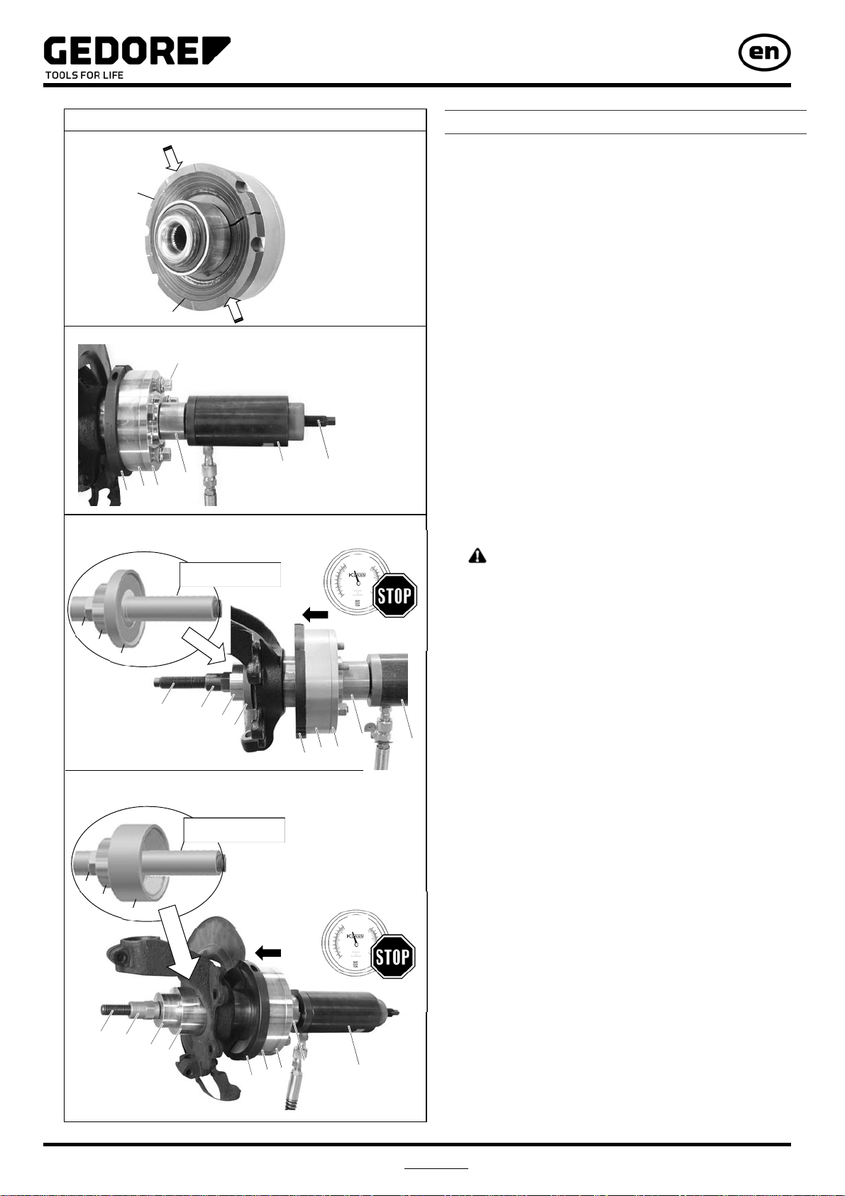
The wheel hub puller: KL-0041-380 enables the quick, safe, and
accurate extraction of wheel hub bearing units or wheel hubs. For this,
the hydraulic cylinder KL-0040-2500 and pull spindle M20 x 550 mm
KL-0039-1920-1 are necessary. Even bonded, seized or corroded
wheel hub bearing units or wheel hubs are no longer an issue thanks to
this tool.
Due to its special design, the wheel hub puller allows the extraction of a
wide range of different wheel hubs equipped with diameters of up to 250
mm.
Note: The plates KL-0041-3821 and KL-0041-3822 are used as
distance adjustment plates. They are needed if during the removal of a
wheel hub it is necessary to support on the rear side of the hooks and if
the supporting surface is not even.
KL-0040-2590 Safety Belt
By fastening the safety belt KL-0040-2590 to the vehicle and to the
hydraulic cylinder KL-0040-2500, the latter is prevented from falling.
7. Maintenance and Repair by the
GEDORE AUTOMOTIVE Service Centre
For safety reasons, as soon as damage is noticed on the wheel bearing
tool, immediate steps must be taken to prevent it from being used. For
professional checking and repair of the tool, please contact the
GEDORE AUTOMOTIVE Service Centre.
Address:
GEDORE AUTOMOTIVE GmbH
Breslauerstr. 41
DE-78166 Donaueschingen
Phone: +49 (0)771 83 22 371
For additional information concerning the use of our wheel bearing tool,
please contact the GEDORE AUTOMOTIVE Service Centre.
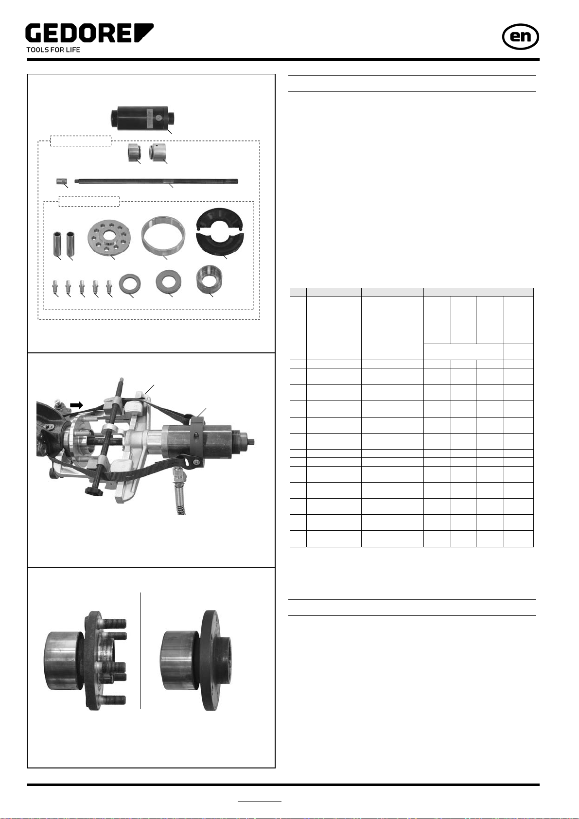
8. Spare Parts List
Pos. Part No. Description Qty.
KL-0041-46 D Wheel bearing tool with hydr. cyl. 1
bestehend aus:
KL-0041-460 D Wheel bearing tool without hydr. cyl. 1
1 KL-0040-2500 Hydraulic cylinder 17 t 1
Pos. Part No. Description Qty.
KL-0041-460 D Wheel bearing tool without hydr. cyl. 1
bestehend aus:
KL-0041-461 D Upgrade Kit Volvo, Ford, Mazda 1
2 KL-0039-1003 Retainer adaptor for hydraulic cylinder 1
3 KL-0039-1002 Retainer adaptor for clamping nut 1
4 KL-0040-3009 Clamping nut, M20 1
5 KL-0039-1920-1 Pull spindle M20 1
Pos. Part No. Description Qty.
KL-0041-461 D Upgrade Kit Volvo 1
bestehend aus:
6 KL-0041-4602 Guide sleeve Ø26.3 mm 1
7 KL-0041-4601 Guide sleeve Ø29.5 mm 1
8 KL-0041-4608 D Cover 1
9 KL-0041-4607 Housing 1
10 KL-0041-4600 D Clamping jaws (pair) Ø78 mm 1
11 KL-0041-3931 Pressure screw M14x1.5 5
12 KL-0039-1272 Pressure ring Ø72 mm 1
13 KL-0039-1288 Pressure ring Ø88 mm 1
14 KL-0039-1682 Pressure-/support sleeve (short) Ø82 mm 1
9. Environmentally Safe Disposal
Dispose of the wheel bearing tool and its packaging material in
compliance with the legal rules and regulations in force.
Fig. 10: Accessory: KL-0215-35 M25
Fig. 11: Accessory: KL-0041-380
Fig. 12: Accessory: KL-0040-2590
Fig. 13: Spare parts: KL-0041-46 D
KL-0041-461 D
KL-0041-460 D 1
2 3
4 5
6 7 8 9 10
11 12 13 14
11
11 11 11