Gedore KL-0041-50 K User manual

GEDORE WELTWEIT / GEDORE WORLDWIDE
Weltweite GEDORE Servicestellen / Niederlassungen finden Sie im Internet unter: www.gedore.com
Worldwide GEDORE service centers / offices are listed on the Internet at: www.gedore.com
GEDORE Automotive GmbH
Breslauer Straße 41
78166 - Donaueschingen
Postfach 1329
78154 Donaueschingen - GERMANY
T +49 (0) 771 / 8 32 23-0
F +49 (0) 771 / 8 32 23-90
www.gedore-automotive.com
GEDORE TOOLS, INC.
Only for USA, Canada & Mexico
Sólo para EE.UU., Canadá y México
Seulement pour les USA, le Canada et le Mexique
7187 Bryhawke Circle, Suite 700
North Charleston, SC 29418, USA
Phone +1-843 / 225 50 15
Fax +1-843 / 225 50 20
info@gedoretools.com
04/2019
www.gedore-automotive.com
0041-51Ke160107.docx
K
L
-0041-50 K
KL-0041-51 K
KL-0041-504
KL-0041-505
Wheel Bearing Tool Kits,
with Hydraulic Cylinder, in a Plastic Storage Case,
Mercedes Vito/Viano/Sprinter, VW Crafter (Pat.)

0041-51Ke160107.docx ©Copyright by GEDORE Automotive GmbH, Germany
23
Instruction Manual EN
Impressum
Im Zuge der Verbesserung und Anpassung an den Stand der Technik behalten wir uns Änderungen im Hinblick auf Aussehen, Abmessungen, Gewichte und Eigenschaften sowie
Leistungen vor.
Damit ist kein Anspruch auf Korrektur oder Nachlieferung bereits gelieferter Produkte verbunden. Streichungen können jederzeit vorgenommen werden, ohne dass ein rechtlicher
Anspruch entsteht.
Alle Hinweise zur Benutzung und Sicherheit sind unverbindlich. Sie ersetzen keinesfalls irgendwelche gesetzlichen oder berufsgenossenschaftlichen Vorschriften.
Für Druckfehler übernehmen wir keine Haftung.
Ein Nachdruck, auch auszugsweise, bedarf der vorherigen schriftlichen Zustimmung durch GEDORE Automotive GmbH.
Alle Rechte weltweit vorbehalten.
Wir verweisen auf unsere Allgemeinen Geschäftsbedingungen, ersichtlich im Impressum unter www.gedore-automotive.com.
© Copyright by GEDORE Automotive GmbH Donaueschingen (GERMANY)
Impressum/Legal Notice
As part of our commitment to continuous product improvement and adaptation to state-of-the art technology, we reserve the right to make modifications to our products with
regard to design, dimension, weight, features and performances at any time and without prior notice.
Thus, the right to adjustments or replacement deliveries of goods already delivered is excluded. Cuts and cancellations can be made by us at any time without notice and no legal
claims against us may arise or be derived from this.
All indications regarding use and safety are given for information only and without any commitment. In no case do they substitute for legal provisions or the regulations of the
Employer’s Liability Insurance Association.
Errors and omissions excepted.
Any reproduction, also in extracts, is subject to the prior written consent of GEDORE Automotive GmbH.
All rights reserved.
We refer to our General Terms and Conditions of Sale under ‘Imprint’ at www.gedore-automotive.com.
© Copyright by GEDORE Automotive GmbH Donaueschingen (GERMANY)
Impressum/Mentions légales
En raison des améliorations continues que nous apportons à nos produits et pour assurer leur adaptation constante à l'évolution des techniques, nous nous réservons le droit de
procéder à des modifications de nos produits quant à l’apparence, aux dimensions, aux poids, aux caractéristiques et aux performances à tout moment sanspréavis et sans obligation
de modifier ou de remplacer des produits précédemment livrés.
Des suppressions peuvent être effectuées à tout moment et sans préavis sans qu’elles puissent donner lieu à réclamation.
Toutes les instructions d’utilisation et conseils de sécurité sont donnés sans engagement de notre part. Ils ne se substituent en aucun cas aux réglementations légales en vigueur
ou à celles émises par les associations professionnelles.
Le plus grand soin possible a été apporté à la rédaction de ce document. Toutefois, nous n’assumons aucune responsabilité pour des erreurs, omissions ou défauts d’impression
éventuels.
Une reproduction, même en partie, ne peut être effectuée qu’après autorisation écrite préalable de GEDORE Automotive GmbH.
Tous droits réservés.
Vous trouverez nos conditions générales de vente, sous Impressum/Mentions légales sur www.gedore-automotive.com.
© Copyright by GEDORE Automotive GmbH Donaueschingen (GERMANY)
English
3 - 19

0041-51Ke160107.docx
©Copyright by GEDORE Automotive GmbH, Germany 3
3
Instruction Manual EN
Table of Contents
Page
1. Essential Safety Notices .......................................................................................................... 4
1.1 Safety Notices and Warnings ................................................................................................................................................4
1.2 Personal Protective Equipment ............................................................................................................................................4
1.3 Intended Use...........................................................................................................................................................................5
1.4 Safe and Proper Use ..............................................................................................................................................................5
1.5 Work Environment..................................................................................................................................................................5
1.6 Appropriate Users ..................................................................................................................................................................5
2. Product Description.................................................................................................................. 6
3. Preparatory Work...................................................................................................................... 7
3.1 Checking the Delivery (See Fig. 1, 2 or 3) ............................................................................................................................7
3.2 Preparing the Vehicle.............................................................................................................................................................7
3.3 Adjusting the Tool by Changing the Pull/Pressure Plate (Only applies to rear-wheel drive)........................................7
4. Examples of Use ....................................................................................................................... 8
4.1 Removing/Installing a Wheel Hub Bearing Unit (Rear-wheel drive)..................................................................................8
4.1.1 Removing the Wheel Hub Bearing Unit. (Rear-wheel drive) ........................................................................................8
4.1.2 Installing the Wheel Hub Bearing Unit. (Rear-wheel drive) .......................................................................................11
4.2 Removing/Installing a Wheel Hub and Wheel Bearing. (All-Wheel Drive) .....................................................................13
4.2.1 Removing the Wheel Hub. (All-Wheel Drive) ...............................................................................................................13
4.2.2 Removing the Wheel Bearing (All-Wheel Drive)..........................................................................................................15
4.2.3 Installing the Wheel Bearing. (All-Wheel Drive) ..........................................................................................................16
4.2.4 Installing the Wheel Hub. (All-Wheel Drive) ................................................................................................................17
5. Care and Storage .................................................................................................................... 18
6. Accessoires ............................................................................................................................ 18
7. Maintenance and Repair by the GEDORE Automotive Service Centre.............................. 18
8. Spare Parts List....................................................................................................................... 19
9. Environmentally Safe Disposal.............................................................................................. 19

0041-51Ke160107.docx ©Copyright by GEDORE Automotive GmbH, Germany
43
Instruction Manual EN
1. Essential Safety Notices
Before using the wheel bearing tool, it is imperative that you read and understand the Instruction Manual. Misuse can lead to
SERIOUS INJURIES and even DEATH.
This Instruction Manual is part of the wheel bearing tool. Keep the Instruction Manual in a safe place for further reference and
pass it on to subsequent users of the wheel bearing tool.
All specific vehicle data stated herein are supplied under reserve and without commitment.
1.1 Safety Notices and Warnings
For better differentiation, the warning notices in this instruction manual are classified as follows:
Warning
sign Sign reads Signification
DANGER
Indicates a hazardous situation which, if not avoided, may result in serious or fatal injuries.
CAUTION
Indicates a hazardous situation which, if not avoided, may result in moderate or minor injuries.
ATTENTION
Indicates a situation which, if not avoided, may result in possible damage to the wheel bearing
tool or its functioning, or to objects in its vicinity.
DANGER
When removing and installing wheel hub bearing units, there is a risk of the tool breaking and falling to pieces. This will lead to
parts becoming projectiles.
Observe and do not exceed the maximum load capacity of the tool.
Use hydraulic pump with pressure gauge KL-0040-2529.
Only use the original spare parts from GEDORE Automotive.
Always keep all parts of your body away from the axial extension of the tool.
CAUTION
A falling tool can cause injuries.
Always wear safety shoes/boots.
ATTENTION
Risk of damage to vehicle and tool.
Lubricate spindles with molybdenum disulphide paste KL-0014-0030 (accessory).
Any work on vehicles should only be performed by qualified specialist personnel observing and complying with the directions,
provisions, and safety regulations specified by the vehicle manufacturer!
Always refer to the vehicle manufacturer’s data and instructions as only these apply to all work that is carried out on the
vehicle.
1.2 Personal Protective Equipment
ALWAYS wear personal protective equipment when using the wheel bearing tool. The wheel bearing tool can cause mechanical
hazards leading to injuries such as contusions, cuts or concussions.
EYE PROTECTION (see OSHA 29 CFR 1910.133 and ANSI Z87) designed to protect you from flying debris/objects
must be worn when using the wheel bearing tool.
Particles may be ejected at high speed while working with the wheel bearing tool and could cause serious injuries to
your eyes.
SAFETY GLOVES must be worn when using the wheel bearing tool.
Working with the wheel bearing tool can cause skin abrasions and contusions.
SAFETY SHOES/BOOTS with slip resistant soles and steel-toe caps (see OSHA 29 CFR 1910.136 and ANSI 241)
must be worn when using the wheel bearing tool.
Falling parts can cause serious injuries to feet and toes.

0041-51Ke160107.docx
©Copyright by GEDORE Automotive GmbH, Germany 5
3
Instruction Manual EN
1.3 Intended Use
The KL-0041-51 K wheel bearing tool kit is only designed for the removal/installation of the wheel hub bearing units that are
found at the front axle of Mercedes Vito/Viano/Sprinter and VW Crafter vehicles with rear-wheel drive.
Note: For the removal/installation of wheel hubs and wheel bearings from/to the front axle of Mercedes Vito/Viano/Sprinter and
VW Crafter vehicles with all-wheel drive, the respective upgrade kits are needed in addition.
The wheel bearing tool may only be used in the manner as described in this Instruction Manual.
Any other use can result in serious injuries or even death.
1.4 Safe and Proper Use
Take the following safety precautions to prevent injuries and damage that could be caused by improper handling or unsafe use
of the wheel bearing tool.
Misuse can result in extremely severe injuries or even death.
NEVER overload the wheel bearing tool.
ALWAYS check the wheel bearing tool prior to EACH use in order to ensure that it is in good order and condition.
ALWAYS replace all damaged or worn parts prior to using the wheel bearing tool.
ONLY use the original spare parts and accessories from GEDORE Automotive on the wheel bearing tool.
1.5 Work Environment
For safety reasons, work with the wheel bearing tool should only be carried out in a safe work environment.
The workplace should always be clean and tidy.
The workplace should be sufficiently large and must be secured.
1.6 Appropriate Users
This Instruction Manual. is designed for technicians/mechanics in workshops.
DO NOT allow children to use the wheel bearing tool.
Purchasers/employers purchasing the wheel bearing tool MUST ensure that any person/employee using the wheel bearing tool
have read and understood this Instruction Manual prior to using the tool. This Instruction Manual MUST be made available to
the users of the wheel bearing tool for reference at all times.

0041-51Ke160107.docx ©Copyright by GEDORE Automotive GmbH, Germany
63
Instruction Manual EN
2. Product Description
2.1 KL-0041-51 K Wheel Bearing Tool Kit,
with 17t Hydraulic Cylinder,
in a Plastic Storage Case,
Mercedes Vito / Viano / Sprinter / VW Crafter
Designed for the front axle of Mercedes Vito/Viano (W639), Sprinter (906),
and VW Crafter (2E/2F) vehicles with rear-wheel drive.
This tool allows the removal and installation of wheel hub bearing units on the
specified front axles to be performed without the need for removing the steering
knuckle from the vehicle.
Note:
The KL-0041-50 K is similar to KL-0041-51 K, however not applicable to Mercedes
Vito/Viano vehicles.
For the removal/installation of wheel hubs and wheel bearings from/to the front axle
of Mercedes Vito/Viano/Sprinter and VW Crafter vehicles with all-wheel drive, the
respective upgrade kits are needed in addition.
Pos. Part No. Description
- KL-0041-51 K
Wheel Bearing Tool Kit with 17t Hydraulic Cylinder,
Mercedes Vito/Viano/Sprinter and VW Crafter
composed of:
- KL-0041-50 K
Wheel Bearing Tool Kit with 17t Hydraulic Cylinder,
Mercedes Sprinter and VW Crafter
4KL-0041-5030 Pull/pressure plate with closing plate, for bearing with 92mm Ø
Pos. Part No. Description
- KL-0041-50 K
Wheel Bearing Tool Kit with 17t Hydraulic Cylinder,
Mercedes Vito/Viano/Sprinter and VW Crafte
r
composed of:
1KL-0040-2500 Hydraulic Cylinder
2 KL-0041-501 Base Tool
2.1 KL-0041-5001 Base Plate
2.2 KL-0041-5002 Supporting Rod with Transverse Bore
2.3 KL-0041-5003 Screw with Cone, M16x1.5x80
2.4 KL-0041-5004 Washer, Ø 19mm (4 units)
2.5 KL-0041-5005 Hexagon Socket Screw, M14x70 (2 units)
2.6 KL-0041-5006 Shoulder Nut, M18 (3 units)
2.7 KL-0041-5007 Reinforcing Rail, 140mm
2.8 KL-0041-5008 Reinforcing Rail, 275mm
2.9 KL-0041-5009 Supporting Rod, 275mm (2 units)
2.10 KL-0041-5010 Adaptor, 2 ¼“-14 UNS to M42x2
2.11 KL-0041-5011 Pull/Pressure Spindle, M20x590
2.12 KL-0041-5012 Steering Knuckle Mounting Bracket
2.13 KL-0041-5013 Pressure Nut with Pilot Pin
3 KL-0041-502
Pull/Pressure Plate Kit with Bridge, for Bearing Ø
96mm, Mercedes Sprinter/VW Crafter
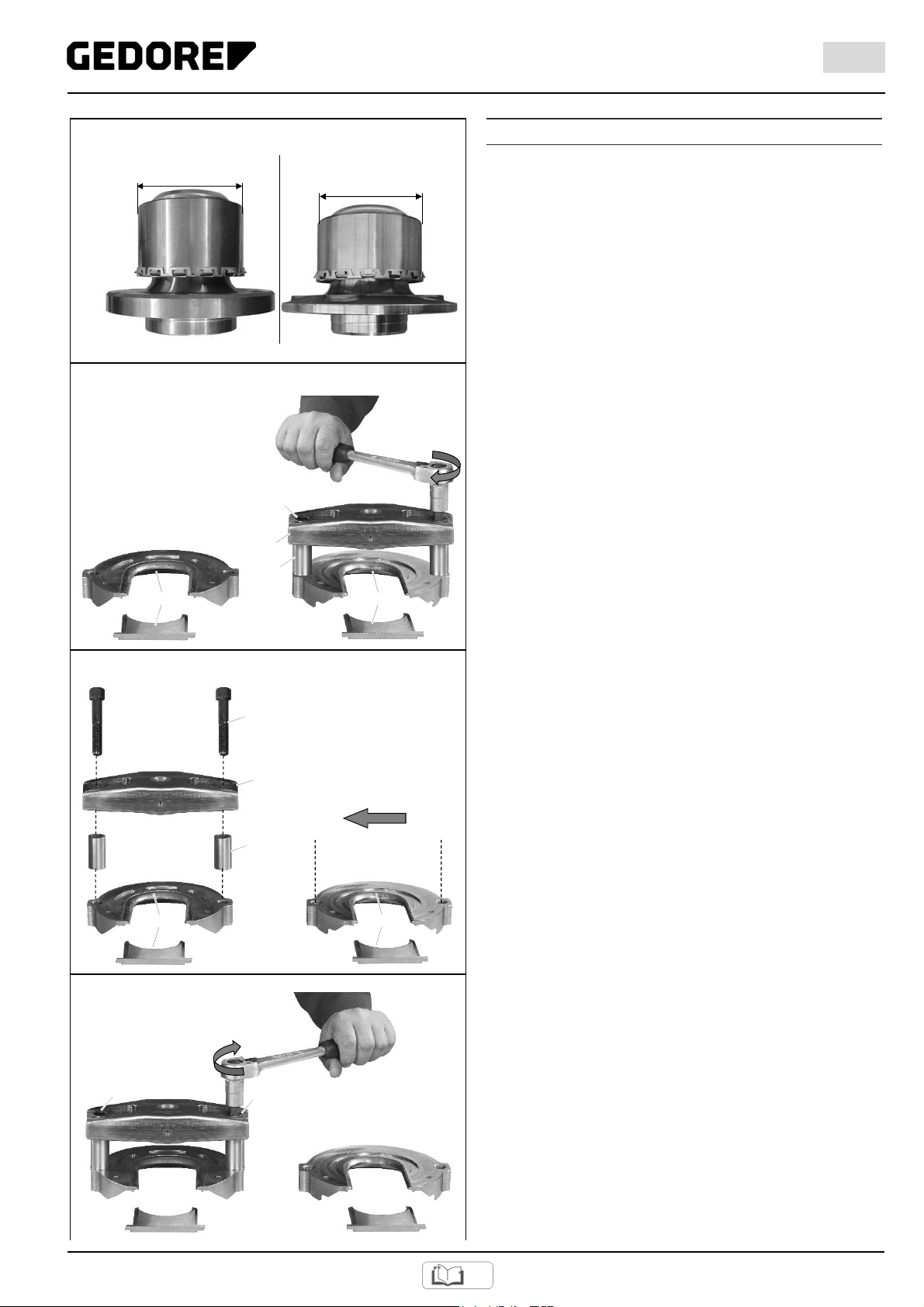
3.1 KL-0041-5020 Pull/Pressure Plate with Closing Plate, for Bearing Ø 96mm
3.2 KL-0041-5021 Bridge with Thread Insert
3.3 KL-0041-5022 Spacer Sleeve, Ø 27x50mm (2 units)
3.4 KL-0041-5023 Hexagon Socket Screw, M16x90 (2 units)
3.5 KL-0041-5024 Knurled Screw, M14x1.5 (3 units)
3.6 KL-0041-5025 Retaining Pin with O-Ring (2 units)
2.2 KL-0041-504 - Upgrade Kit, (Accessory)
Mercedes Sprinter/VW Crafter
with All-Wheel Drive
Pos. Part No. Description
- KL-0041-51 K Upgrade Kit, Mercedes Sprinter/VW Crafter
with All-Wheel Drive
composed of:
5KL-0039-1003 Retaining Adaptor with O-Rings, for Hydraulic Cylinder
6KL-0039-1002 Retaining Adaptor with O-Rings, for Clamping Nut (M20)
and Pressure Spindle
7KL-0039-1920-4 Clamping Nut, Ø 38mm
8KL-0041-5041 Pressure Nut with Pilot Pin
- KL-0040-506 Small Upgrade Kit, Mercedes Sprinter/ VW Crafte
r
9KL-0039-1270 Pressure Ring, Ø 70mm
10 KL-0039-1295 Pressure Ring, Ø 95mm
11 KL-0039-1351 Centring Ring, Ø 51mm
2.3 KL-0041-505 Upgrade Kit (Accessory)
Mercedes Vito/Viano All-Wheel Drive
Pos. Part No. Description
- KL-0041-51 K Upgrade Kit (Accessory)
Mercedes Vito/Viano All-Wheel Drive
composed of:
5KL-0039-1003 Retaining Adaptor with O-Rings, for Hydraulic
Cylinder
6KL-0039-1002 Retaining Adaptor with O-Rings, for Clamping Nut
(M20) and Pressure Spindle
7KL-0039-1920-4 Clamping Nut, Ø 38mm
8KL-0041-5041 Pressure Nut with Pilot Pin
- KL-0040-507 Small Upgrade Kit, Mercedes Vito/Viano
9KL-0039-1270 Pressure Rin
g
, Ø 70mm
12 KL-0039-1291 Pressure Ring, Ø 91mm
13 KL-0039-1274 Pressure Ring, Ø 74mm
14 KL-0039-1350 Centring Ring, Ø 50mm
2.4 Technical Data
Maximum load capacity of the tool:................................................................... 17t
Maximum load capacity of the hydraulic cylinder:............................................. 17t
Fig. 1: KL-0041-51 K
Fig. 2: KL-0041-504 Upgrade Kit (Accessory)
Fig. 3: KL-0041-505 Upgrade Kit (Accessory)
1
2
3
3.1
2.12
2.1
2.10 2.13
2.4
2.6
2.6
2.7
2.3
2.5
2.8 2.9
2.2
3.6
3.3
3.4
3.6
3.3 3.4 3.25
3.2
4
5 6
7 8
9 10 11
KL-0041-506
5 6
8 9
9 12 13 14
KL-0041-507
KL-0041-50 K

0041-51Ke160107.docx
©Copyright by GEDORE Automotive GmbH, Germany 7
3
Instruction Manual EN
3. Preparatory Work
Before the first commissioning of the wheel bearing tool kit,
check and confirm you have all the parts listed in the scope of
delivery. Then, read and follow the mounting instructions.
3.1 Checking the Delivery (See Fig. 1, 2 or 3)
3.2 Preparing the Vehicle
Loosen and/or remove components/parts as necessary.
3.3 Adjusting the Tool by Changing the Pull/Pressure
Plate (Only applies to rear-wheel drive)
Note: It is important to know that the Mercedes-Benz Sprinter
and VW Crafter vehicles feature a larger wheel bearing diameter
than the Mercedes-Benz Vito/Viano models. (Fig. 4)
Therefore, it may be necessary to adjust the tool and change the
pull/pressure plate with closing plate depending on the type of
vehicle to be worked on!
- With Sprinter/Crafter: Ø 96mm = pull/pressure plate “3.1“,
- With Vito / Viano: Ø 92mm = pull/pressure plate “4“,
1. Loosen hex socket screws “3.4“ on bridge “3.2“. (Fig. 5)
2. To adjust the tool to the respective bearing diameter, remove
hex socket screws “3.4“, sleeves “3.3“ and bridge “3.2“
from the inappropriate pull/pressure plate. Then, assemble
these with the other pull/pressure plate. (Fig. 6)
3. Tighten hex socket screws “3.4“ to approx. 30 Nm. (Fig. 7)
Fig. 4: Wheel bearing diameter
Crafter/Sprinter Vito/Viano
Fig. 5: Loosen hex socket screws on bridge
Fig. 6: Position hex socket screws, sleeves and bridge on
respective appropriate pull/pressure plate.
Fig. 7: Tighten hex socket screws to approx. 30 Nm.
Ø 96mm
Ø 92mm
3.1 4
3.4
3.3
3.2
3.1 4
3.4
3.3
3.2
3.4
3.4

0041-51Ke160107.docx ©Copyright by GEDORE Automotive GmbH, Germany
83
Instruction Manual EN
4. Examples of Use
4.1 Removing/Installing a Wheel Hub Bearing Unit
(Rear-wheel drive)
The following instructions describe the procedure of removing
and installing a wheel hub bearing unit from/to Mercedes
Sprinter/Vito/Viano and VW Crafter vehicles with rear-wheel
drive).
4.1.1 Removing the Wheel Hub Bearing Unit.
(Rear-wheel drive)
1. Insert bridge “3.2“ along with appropriate pull/pressure plate
“3.1“ or “4“ behind the wheel hub (between wheel hub and
steering knuckle). (Fig. 8)
Note: Remember that there are two different wheel bearing
diameters. It may therefore be necessary to adjust the tool
by changing the pull/pressure plate depending on the type of
vehicle to be worked on (see Section 3.3).
2.
CAUTION
Once the wheel hub bearing unit has been released, there is
a risk that it could fall.
Secure wheel hub bearing unit to prevent it from falling.
Insert retaining pins “3.6“ into appropriate pull/pressure plate
“3.1“ or “4“. (Fig. 9)
3. Fasten supporting rods “2.9“ to steering knuckle by means
of hex socket screws “2.5“ and appropriate reinforcing rail
“2.7“ or “2.8“ as shown in Fig. 10 Aand Fig. 10 B. Tighten
down hex socket screws “2.5“ to approx. 25 Nm.
Note: The reinforcing rails come in two different lengths.
Always be sure to use the correct rail depending on the type
of vehicle.
- With Sprinter/Crafter: Use reinforcing rail “2.7“ or “2.8“.
- With Vito/Viano: Use reinforcing rail “2.7“
4. Slide one washer “2.4“ onto each of supporting rods “2.9“.
(Fig. 10 A).
5. Note: When using reinforcing rail “2.7“, be sure to place
base plate “2.1“ with its small slotted holes onto supporting
rods “2.9“.
When using reinforcing rail “2.8“, be sure to place base
plate “2.1“ with its large slotted holes onto supporting
rods “2.9“.
Place base plate “2.1“ onto the two supporting rods “2.9“.
Loosely screw one shoulder nut “2.6“ onto each of
supporting rods “2.9“. Do not tighten yet. (Fig. 11)
6. Fitted with either one or two washers “2.4“ (depending on
vehicle) insert supporting rod with transverse bore “2.2“.
into base plate “2.1“. Next, loosely screw on shoulder
nut “2.6“ and screw in screw “2.3“.(Fig. 12 A)
Tighten screw “2.3“ to approx. 25 Nm.
Note:
- With Sprinter/Crafter, use two washers “2.4“.
- With Vito/Viano, use one washer “2.4“.
(See Fig. 12 B)
Fig. 8: Position bridge with pull/pressure plate.
Fig. 9: Insert retaining pins
Fig. 10: Secure supporting rods and reinforcing rail.
Fig. 11: Mount base plate to supporting rods.
Fig. 12: Secure supporting rod.
3.6
3.1 or 4
2.1
2.9
2.6
2.6
“A“
“B“
2.2
2.2 2.4
2.1
2.6
2.3
3.1 or 4
3.2
“A“ “B“
2.5
2.9
2.9
2.4
2.4
2.5
2.7 or 2.8

0041-51Ke160107.docx
©Copyright by GEDORE Automotive GmbH, Germany 9
3
Instruction Manual EN
7. To secure base plate, screw on 3x shoulder nuts “2.6“ and
tighten down to approx. 25 Nm. (Fig. 13)
8. Mount steering knuckle mounting bracket “2.12“ to
supporting rod with transverse bore “2.2“ and wishbone.
(Fig. 14)
9. Screw adaptor “2.10“ on pulling side of hydraulic cylinder
“1“.
Screw pull/pressure spindle “2.11“ into hydraulic
cylinder “1“ until the spindle protrudes about 10cm from the
hydraulic cylinder pulling side. (Fig. 15)
10.Screw hydraulic cylinder “1“ with adaptor “2.10“ into base
plate “2.1“. (Fig. 16)
11.
ATTENTION
Risk of damage to the tool if the spindle is not fully screwed
into the bridge.
Be sure to screw in pull/pressure spindle “2.11“ until its
thread protrudes from the reverse side of bridge “3.2“.
Screw pull/pressure spindle “2.11“ into bridge “3.2“ until
spindle thread slightly protrudes from reverse side of
bridge “3.2“. (see arrow in Fig. 17)
Fig. 13: Tighten down shoulder nuts.
Fig. 14: Mount steering knuckle mounting bracket.
Fig. 15: Prepare hydraulic cylinder.
Fig. 16: Screw hydraulic cylinder into base plate.
Fig. 17: Screw pull/pressure spindle into bridge.
2.6
2.6 2.6
2.2
2.12
2.10 1
Pulling side Pushing side
2.11
Approx. 10cm
2.10 1
2.1
2.11
3.2

0041-51Ke160107.docx ©Copyright by GEDORE Automotive GmbH, Germany
10 3
Instruction Manual EN
12. Connect hydraulic hand pump (accessory) to hydraulic
cylinder “1“.
13.
DANGER
When removing the wheel hub bearing unit, there is a risk
that the tool could break and fall to pieces. This will lead to
parts becoming projectiles.
Observe and do not exceed the maximum load capacity of
the tool.
Use hydraulic pump with pressure gauge KL-0040-2529.
Only use the original spare parts from GEDORE
Automotive.
Always keep all parts of your body away from the axial
extension of the tool.
During the removal process, the pressure must not exceed
17t, otherwise the complete steering knuckle along with the
wheel hub bearing unit will have to be replaced.
Operate hydraulic pump and remove wheel hub bearing unit
from steering knuckle. (Fig. 18)
Note: Remember that the stroke of hydraulic cylinder "1" is
45mm. As a result, the extraction of the wheel hub bearing
unit needs to be carried out in several steps.
As soon as you notice high pressure on the pump lever,
interrupt removal process and re-position hydraulic
cylinder “ 1“. For this, release pressure on hydraulic pump
and unscrew pull/pressure spindle “2.11“ until hydraulic
cylinder “1“ is fully relieved from pressure. Then, re-screw
pull/pressure spindle “2.11“ into bridge “3.2“.(See Fig. 18
and 19)
14.
CAUTION
There is a risk that the wheel hub bearing unit, bridge “3.2“
and pull/pressure plate could fall.
With one hand, hold wheel hub bearing unit with bridge
“3.2“ and pull/pressure plate to prevent these from falling.
Unscrew pull/pressure spindle “2.11“ from bridge “3.2“.
Remove wheel hub bearing unit along with bridge “3.2“ and
pull/pressure plate. (Fig. 19) Next, unscrew hydraulic
cylinder “1“ from base plate “2.1.
15. Remove bridge “3.2“ and pull/pressure plate from
dismantled wheel hub bearing unit. (Fig. 20)
16. Remove residues of the snap ring and thoroughly clean the
wheel bearing bore in the steering knuckle. (Fig. 21)
Fig. 18: Remove wheel hub bearing unit.
Fig. 19: Remove wheel hub bearing unit and
pull/pressure plate assembly.
Fig. 20: Remove pull/pressure plate assembly from
wheel hub bearing unit.
Fig. 21: Clean wheel bearing bore.
3.2 1
2.11
3.2
2.11
1
2.1
3.2

0041-51Ke160107.docx
©Copyright by GEDORE Automotive GmbH, Germany 11
3
Instruction Manual EN
4.1.2 Installing the Wheel Hub Bearing Unit.
(Rear-wheel drive)
1. Insert bridge “3.2“ along with pull/pressure plate“3.1“ or “4“
(as appropriate) into new wheel hub bearing unit. (Fig. 22)
2.
Attention
Risk of damage to pull/pressure plate.
Make absolutely sure that the closing plate is properly
inserted in the pull/pressure plate.
Insert closing plate with its rounded side facing upwards
(towards the wheel hub). (Fig. 23)
3. Attention
Risk of damage to closing plate.
Make sure that knurled screws “3.5“ do not push against
the closing plate of the pull/pressure plate.
Manually screw 3x knurled screws “3.5“ into the wheel bolt
bore holes of the wheel hub bearing unit. Tighten screws
until these engage the respective groove of the pull/pressure
plate, thus centring the latter on the wheel hub. (Fig. 24)
4.
CAUTION
There is a risk that bridge
“3.2“
and pull/pressure could fall.
Secure bridge “3.2“ and pull/pressure plate against falling.
Insert retaining pins “3.6“ into pull/pressure plate as far as it
goes. (Fig. 25)
5. On the pushing side of hydraulic cylinder “1“, screw
pressure nut “2.13“ onto pull/pressure spindle “2.11“ as
shown in Fig. 26.
Fig. 22: Insert bridge along with pull/pressure plate into new
wheel hub bearing unit.
Fig. 23: Insert closing plate.
Fig. 24: Screw knurled screws into
wheel bolt bore holes.
Fig. 25: Insert retaining pins into pull/pressure plate.
Fig. 26: Hydraulic cylinder with pull/pressure spindle and
pressure nut.
3.2
Closing plate
3.5
3.5 3.5
3.6 3.6
1
Pulling side
Pushing side
2.13 2.11
3.2
3.1 or 4

0041-51Ke160107.docx ©Copyright by GEDORE Automotive GmbH, Germany
12 3
Instruction Manual EN
6. Screw hydraulic cylinder “1“ with its pushing side into base
plate “2.1“. (Fig. 27)
7.
Attention
Risk of damage to pull/pressure plate
The closing plate of the pull/pressure plate must face
upwards; otherwise it will fall off the tool.
Check to make sure that the closing plate is properly
seated in the pull/pressure plate. (Fig. 28)
Apply bridge “3.2“ along with pull/pressure plate and wheel
hub bearing unit against steering knuckle.(Fig. 28)
Screw pull/pressure spindle “2.11“ into hydraulic cylinder “1“
until pressure nut “2.13“ engages bridge “3.2“ of the
pull/pressure plate. (Fig. 28)
8. Connect hydraulic pump (accessory) to hydraulic
cylinder “1“.
9.
DANGER
When installing the wheel hub bearing unit, there is a risk
that the tool could break and fall to pieces. This will lead to
parts becoming projectiles.
Observe and do not exceed the maximum load capacity of
the tool.
Use hydraulic pump with pressure gauge KL-0040-2529.
Only use the original spare parts from GEDORE
Automotive.
Always keep all parts of your body away from the axial
extension of the tool.
Operate hydraulic pump and install wheel hub bearing unit
into steering knuckle. (Fig. 29)
Note: Remember that the stroke of hydraulic cylinder "1" is
45mm. As a result, the installation of the wheel hub bearing
unit needs to be carried out in several steps.
As soon as you notice high pressure on the pump lever,
interrupt installation process and re-position hydraulic
cylinder “ 1“. For this, release pressure on hydraulic pump
and screw in pull/pressure spindle “2.11“ until pressure nut
“2.13“ rests against bridge “3.2“. Continue installation
process. (See Fig. 28 and 29)
10. Release pressure from hydraulic pump and dismantle tool.
11. Check to make sure that snap ring is seated properly in the
groove. (Fig. 30)
12. Reassemble the vehicle according to the manufacturer's
instructions.
Fig. 27: Screw hydraulic cylinder into base plate.
Fig. 28: Apply bridge with pull/pressure plate along with
wheel hub bearing unit against steering knuckle.
Fig. 29: Install wheel hub bearing unit
Fig. 30: Snap ring is properly seated in the groove.
1
2.1
3.2 1 2.11
2.13
2.13
3.2
Closing plate

0041-51Ke160107.docx
©Copyright by GEDORE Automotive GmbH, Germany 13
3
Instruction Manual EN
4.2 Removing/Installing a Wheel Hub and
Wheel Bearing. (All-Wheel Drive)
The following instructions describe the procedure of removing
and installing a wheel hub and a wheel bearing from/to
Mercedes Sprinter/Vito/Viano and VW Crafter vehicles with all-
wheel drive)
Note: For this, the respective upgrade kits are needed.
4.2.1 Removing the Wheel Hub. (All-Wheel Drive)
1. Fasten supporting rods “2.9“ to steering knuckle by means
of hex socket screws “2.5“ and appropriate reinforcing rail
“2.7“ or “2.8“ as shown in Fig. 31 Aand Fig. 31 B. Tighten
hex socket screws “2.5“ to approx. 25 Nm.
Note: The reinforcing rails come in two different lengths.
Always be sure to use the correct rail depending on the type
of vehicle.
- With Sprinter/Crafter: Use reinforcing rail “2.7“ or “2.8“.
- With Vito/Viano: Use reinforcing rail “2.7“
2. Slide one washer “2.4“ onto each of supporting rods “2.9“.
(Fig. 31 A).
3. Note: When using reinforcing rail “2.7“, be sure to place
base plate “2.1“ with its small slotted holes onto supporting
rods “2.9“.
When using reinforcing rail “2.8“, be sure to place base
plate “2.1“ with its large slotted holes onto the supporting
rods “2.9“.
Place base plate “2.1“ onto the two supporting rods “2.9“.
Loosely screw one shoulder nut “2.6“ onto each of the
supporting rods “2.9“. Do not tighten yet. (Fig. 32)
4. Fitted with washer/s “2.4“, swivel supporting rod with
transverse bore “2.2“ into base plate “2.1“ (see Fig 33 B).
Next, loosely screw on shoulder nut “2.6“ and screw in
screw “2.3“.(Fig. 33 A)
Tighten screw “2.3“ to approx. 25 Nm.
Note:
- With Sprinter/Crafter, use two washers “2.4“.
- With Vito/Viano, use one washer “2.4“.
(See Fig. 33 B)
5. To secure base plate, screw on 3x shoulder nuts “2.6“ and
tighten down to approx. 25 Nm. (Fig. 33 A).
6. Mount steering knuckle mounting bracket “2.12“ to
supporting rod with transverse bore “2.2“ and wishbone.
(Fig. 34)
Fig. 31: Secure supporting rods with reinforcing rail.
Fig. 32: Mount base plate to supporting rods.
Fig. 33: Secure supporting rod.
Fig. 34: Mount steering knuckle mounting bracket.
“A“
“B“ 2.5
2.9
2.9
2.4
2.4
2.5
2.7 or 2.8
2.1
2.6
2.6
2.9
2.9
2.2
“A”
“B“
2.2
2.4
2.6
2.3 2.1
2.6
2.6
2.2
2.12

0041-51Ke160107.docx ©Copyright by GEDORE Automotive GmbH, Germany
14 3
Instruction Manual EN
7. Screw adaptor “2.10“ onto pulling side of hydraulic cylinder
“1“.
Screw pull/pressure spindle “2.11“ into hydraulic
cylinder “1“ until the spindle protrudes about 35cm from the
hydraulic cylinder pulling side. (Fig. 35)
8. Screw hydraulic cylinder “1“ with adaptor “2.10“ into base
plate “2.1“. (Fig. 36 A).
9. Screw clamping nut “7“ onto pull/pressure spindle “2.11“.
(Fig. 36 B)
10. Connect hydraulic pump (accessory) to hydraulic
cylinder “1“.
11.
DANGER
When removing the wheel hub, there is a risk that the tool
could break and fall to pieces. This will lead to parts
becoming projectiles.
Observe and do not exceed the maximum load capacity of
the tool.
Use hydraulic pump with pressure gauge KL-0040-2529.
Only use the original spare parts from GEDORE
Automotive.
Always keep all parts of your body away from the axial
extension of the tool.
During the removal process, the pressure must not
exceed 17t, otherwise the complete steering knuckle along
with the wheel hub and wheel bearing will have to be
replaced.
Operate hydraulic pump and remove wheel hub from wheel
bearing. (Fig. 37)
Note: Remember that the stroke of hydraulic cylinder "1" is
45mm. As a result, the removal of the wheel hub needs to
be carried out in several steps. As soon as you notice high
pressure on the pump lever, interrupt removal process and
re-position hydraulic cylinder “ 1“.
For this, release pressure on hydraulic pump. Then, re-
adjust pull/pressure spindle “2.11“ until clamping nut “7“
rests against the wheel hub. (See Fig. 36 B and 37)
12. Remove wheel hub from pull/pressure spindle “2.11“. For
this, release pressure on hydraulic pump and unscrew
hydraulic cylinder “1“ and adaptor “2.10“ from base
plate “2.1“. Next, unscrew clamping nut “7“ from
pull/pressure spindle “2.11“ and remove wheel hub.
(Fig. 37)
13. If necessary, remove inner bearing race from wheel hub, e.g.
with the aid of the KL-0042-90 Kpuller set (accessory).
(Fig. 38)
Fig. 35: Prepare hydraulic cylinder.
Fig. 36: Screw hydraulic cylinder into base plate.
Screw on clamping nut.
Fig. 37: Remove wheel hub
Fig. 38: Pull off inner bearing race, e.g. with the aid of
KL-0042-90 K (accessory).
2.10 1
Pulling side Pushing side
2.11
Approx. 35cm
KL-0042-90
K
(
Accessor
y)
2.10
1
2.1
7
2.11
2.11
“A“
“B“
2.11
1
2.1 2.10
17t

0041-51Ke160107.docx
©Copyright by GEDORE Automotive GmbH, Germany 15
3
Instruction Manual EN
4.2.2 Removing the Wheel Bearing (All-Wheel Drive)
1. Screw hydraulic cylinder “1“ with adaptor “2.10“ into base
plate “2.1“. (Fig. 39 A).
2. Slide pressure ring “9“ with adaptor “6“ and centring
ring “11 (or 14“ as appropriate) onto pull/pressure
spindle “2.11“ as shown in Fig 39 B. Next, screw on
clamping nut “7“.
Note:
- With Sprinter/Crafter: Use centring ring “11“.
- With Vito/Viano: Use centring ring “14“
3. Connect hydraulic pump to hydraulic cylinder “1“.
4.
DANGER
When removing the wheel bearing, there is a risk that the
tool could break and fall to pieces. This will lead to parts
becoming projectiles.
Observe and do not exceed the maximum load capacity of
the tool.
Use hydraulic pump with pressure gauge KL-0040-2529.
Only use the original spare parts from GEDORE
Automotive.
Always keep all parts of your body away from the axial
extension of the tool.
During the removal process, the pressure must not exceed
17t, otherwise the complete steering knuckle along with the
wheel hub and wheel bearing will have to be replaced.
Operate hydraulic pump and remove wheel bearing from
steering knuckle. (Fig. 40)
Note: Remember that the stroke of hydraulic cylinder "1" is
45mm. As a result, the removal of the wheel bearing needs
to be carried out in several steps. As soon as you notice high
pressure on the pump lever, interrupt removal process and
re-position hydraulic cylinder “ 1“.
For this, release pressure on hydraulic pump. Then, re-
adjust pull/pressure spindle “2.11“ until clamping nut “7“ ,
pressure ring “9“ with adaptor “6“ and centring ring “11 or
14“ rest against the wheel bearing. (See Fig. 39 B and 40)
5. Remove wheel bearing from pull/pressure spindle “2.11“
(Fig. 40). For this, release pressure on hydraulic pump and
unscrew hydraulic cylinder “1“ and adaptor “2.10“ from
base plate. Next, unscrew clamping nut “7“, pressure
ring “9“ with adaptor “6“ and centring ring “11 or 14“ from
pull/pressure spindle “2.11“. Remove wheel bearing.
6. Remove residues of safety ring and thoroughly clean the
wheel bearing bore in the steering knuckle. (Fig. 41)
Fig. 39: Screw hydraulic cylinder into base plate.
Mount pressure ring and
adaptor. Screw on clamping nut.
Fig. 40: Remove wheel bearing
Fig. 41: Clean wheel bearing bore.
2.11
1
2.1 2.10
17t
2.10
1
2.1
2.11
7
“A“
“B“
6
9
11 or 14
Wheel bearing
2.11

0041-51Ke160107.docx ©Copyright by GEDORE Automotive GmbH, Germany
16 3
Instruction Manual EN
4.2.3 Installing the Wheel Bearing. (All-Wheel Drive)
1. On the pushing side of hydraulic cylinder “1“, screw
pressure nut “8“ onto pull/pressure spindle “2.11“ as shown
in Fig. 42.
2. Screw hydraulic cylinder “1“ with its pushing side into base
plate “2.1“. (Fig. 43)
3. Place retaining adaptor “6“ with pressure ring “10 or 12“
and centring ring “11 or 14“ as appropriate onto pressure
nut “8“. (Fig. 44 B)
Note:
- With Sprinter/Crafter: Use pressure ring “10“,
and centring ring “11“.
- With Vito/Viano: Use pressure ring “12“,
and centring ring “14“.
4. Slide new wheel bearing onto centring ring “11 or 14“. Screw
pull/pressure spindle “2.11“ into hydraulic cylinder until
wheel bearing rests against steering knuckle. (Fig. 44
A and 44 B)
5. Connect hydraulic pump to hydraulic cylinder “1“.
6.
DANGER
When installing the wheel bearing, there is a risk that the tool
could break and fall to pieces. This will lead to parts
becoming projectiles.
Observe and do not exceed the maximum load capacity of
the tool.
Use hydraulic pump with pressure gauge KL-0040-2529.
Only use the original spare parts from GEDORE
Automotive.
Always keep all parts of your body away from the axial
extension of the tool.
Operate hydraulic pump and install wheel bearing into
steering knuckle. (Fig. 45)
Note: Remember that the stroke of hydraulic cylinder "1" is
45mm. As a result, the installation of the wheel bearing
needs to be carried out in several steps. As soon as you
notice high pressure on the pump lever, interrupt installation
process and re-position hydraulic cylinder “ 1“.
For this, release pressure on hydraulic pump. Then, re-
adjust pull/pressure spindle “2.11“ until pressure ring “10 or
12“ rests against the wheel bearing. Continue installation
process until wheel bearing is properly installed in steering
knuckle.
The wheel bearing is correctly installed when its safety ring
engages the groove of the steering knuckle and pressure on
hydraulic pump increases noticeably. (See Fig. 44 B and 45)
7. Release pressure from hydraulic pump and remove tool from
steering knuckle.
8. Check to make sure that safety ring is properly seated in the
groove. (Fig. 46)
Fig. 42: Prepare hydraulic cylinder.
Fig. 43: Screw hydraulic cylinder into base plate.
Fig. 44: Mount retaining adaptor, centring ring and pressure ring.
Slide wheel bearing onto centring ring.
Fig. 45: Install wheel bearing. Safety ring properly engaged.
Fig. 46: Safety ring is fully engaged in the groove.
1
Pulling side
Pushing side
8 2.11
1
2.1
11 or 14
Wheel bearing
“B“
6
8
10 or 12
“A“
1
2.1
2.11
2.11
1
10 or 12
17t

0041-51Ke160107.docx
©Copyright by GEDORE Automotive GmbH, Germany 17
3
Instruction Manual EN
4.2.4
Installing the Wheel Hub.
(All-Wheel Drive)
1. Screw retaining adaptor “5“ onto pulling side of hydraulic
cylinder “1“ . Then, slide pressure ring “10 or 13“ onto
retaining adaptor “5“.
Screw pull/pressure spindle “2.11“ into hydraulic
cylinder “1“ until the spindle protrudes about 20cm from the
hydraulic cylinder pulling side. (Fig. 47)
Note:
- With Sprinter/Crafter: Use pressure ring “10“.
- With Vito/Viano: Use pressure ring “13“
2. Slide wheel hub onto pull/pressure spindle “2.11“ and insert
tool through wheel bearing as shown in Fig. 48 A. Slide
pressure ring “9“ with adaptor “6“ onto pull/pressure
spindle “2.11“ as shown in Fig 48 B. Next, screw on
clamping nut “7“.
3. Connect hydraulic pump to hydraulic cylinder “1“.
4.
DANGER
When installing the wheel hub, there is a risk that the tool
could break and fall to pieces. This will lead to parts
becoming projectiles.
Observe and do not exceed the maximum load capacity of
the tool.
Use hydraulic pump with pressure gauge KL-0040-2529.
Only use the original spare parts from GEDORE
Automotive.
Always keep all parts of your body away from the axial
extension of the tool.
Operate hydraulic pump and install wheel hub into wheel
bearing. (Fig. 49)
Note: Remember that the stroke of hydraulic cylinder "1" is
45mm. As a result, the installation of the wheel hub needs to
be carried out in several steps. As soon as you notice high
pressure on the pump lever, interrupt installation process
and re-position hydraulic cylinder “ 1“.
For this, release pressure on hydraulic pump. Then, re-
adjust pull/pressure spindle “2.11“ until pressure ring “9“
rests against the wheel hub. Continue installation process
until wheel hub is properly installed in wheel bearing. (See
Fig. 48 B and 49)
5. Release pressure from hydraulic pump and remove tool from
steering knuckle.
6. Check to make sure that wheel hub is properly installed in
wheel bearing. (Fig. 50)
7. Reassemble the vehicle according to the manufacturer's
instructions.
Fig. 47: Prepare hydraulic cylinder.
Fig. 48: Slide on wheel hub. Mount pressure ring and retaining
adaptor. Screw on clamping nut.
Fig. 49: Install wheel hub.
Fig. 50: Wheel hub and wheel bearing installed.
5
Pulling side Pushing side
10 or 13 1
Approx. 20cm
2.11
1
17t
9
“B“
2.11
7
“A“
1
Wheel
hub
2.11
6

0041-51Ke160107.docx ©Copyright by GEDORE Automotive GmbH, Germany
18 3
Instruction Manual EN
5. Care and Storage
ATTENTION Petroleum ether and chemical solvents can damage plastic parts.
Always clean all parts after their use with a clean cloth only. In order to protect
against corrosion, lightly lubricate all metal parts after their use with oil and store
them in a clean and dry place.
6. Accessoires :
KL-0215-35 M25 - Hydraulic Hand Pump
The hydraulic hand pump KL-0215-35 M25 is used to operate the KL-0040-2500
hydraulic cylinder.
KL-0041-504 - Upgrade Kit, Mercedes Sprinter/
VW Crafter with All-Wheel Drive
Designed for the front axle of Mercedes Sprinter (906) and VW Crafter (2E/2F)
vehicles with all-wheel drive. The kit allows the removal and installation of wheel
bearings and hubs. For this, wheel bearing tool KL-0041-50 or KL-0041-51 K is
needed in addition.
Pos. Part No. Description Qty
5 KL-0039-1003 Retaining Adaptor with O-Rings, for Hydraulic
Cylinder
1
6 KL-0039-1002 Retaining Adaptor with O-Rings, for Clamping Nut
(M20) and Pressure Spindle
1
7 KL-0039-1920-4 Clamping Nut, Ø 38mm 1
8 KL-0041-5041 Pressure Nut with Pilot Pin 1
- KL-0041-506 Upgrade Kit (Small Kit), Mercedes Sprinter/VW
Crafter with All-Wheel Drive 1
KL-0041-505 - Upgrade Kit, Mercedes Vito/Viano
with All-Wheel Drive
Designed for the front axle of Mercedes Vito/Viano (W639) vehicles with all-
wheel drive. The kit is designed for the removal and installation of wheel bearings
and hubs. For this, the wheel bearing tool KL-0041-50 Kor KL-0041-51 K is
necessary in addition.
Pos. Part No. Description Qty
5 KL-0039-1003 Retaining Adaptor with O-Rings, for Hydraulic
Cylinder
1
6 KL-0039-1002 Retaining Adaptor with O-Rings, for Clamping Nut
(M20) and Pressure Spindle
1
7 KL-0039-1920-4 Clamping Nut, Ø 38mm 1
8 KL-0041-5041 Pressure Nut with Pilot Pin 1
- KL-0041-507 Upgrade Kit (Small Kit), Mercedes-Benz Vito/Viano
with All-Wheel Drive 1
KL-0041-506 - Upgrade Kit (Small Kit), Mercedes-
Benz Sprinter/VW Crafter with
All-Wheel Drive
Designed for the front axle of Mercedes Sprinter (906) and VW Crafter (2E/2F)
vehicles with all-wheel drive. The kit is designed for the removal and installation
of wheel bearings and hubs. For this, the wheel bearing tool KL-0041-50 or
KL-0041-51 K, retaining adaptor KL-0039-1002, retaining adaptor KL-0039-1003,
clamping nut KL-0039-1920-4, and pressure nut KL-0041-5041 are necessary in
addition.
Pos. Part No. Description Qty
9 KL-0039-1270 Pressure ring, Ø 70mm 1
10 KL-0039-1295 Pressure Ring, Ø 95mm 1
11 KL-0039-1351 Centring ring, Ø 51mm 1
KL-0041-507 - Upgrade Kit (Small Kit), Mercedes
Vito/Viano with All-Wheel Drive
Designed for the front axle of Mercedes Vito/Viano (W639) vehicles with all-
wheel drive. The kit allows for the removal and installation of wheel bearings and
hubs. For this, the wheel bearing tool KL-0041-50 K or KL-0041-51 K, retainer
adaptor KL-0039-1002, retainer adaptor KL-0039-1003, and pressure nut
KL-0041-5041 are necessary in addition.
Pos. Part No. Description Qty
9 KL-0039-1270 Pressure Ring, Ø 70mm 1
12 KL-0039-1291 Pressure Ring, Ø 91mm 1
13 KL-0039-1274 Pressure Ring, Ø 74mm 1
14 KL-0039-1350 Centring Ring, Ø 50mm 1
7. Maintenance and Repair by the GEDORE
Automotive Service Centre.
For safety reasons, as soon as damage is noticed on the wheel bearing
tool, immediate steps must be taken to prevent it from being used. For
professional inspection and repair of the wheel bearing tool, please
contact the GEDORE Automotive Service Centre.
Address:
GEDORE Automotive GmbH
Breslauerstraße 41 // 78166 Donaueschingen
Phone: 0771 83 22 371 / Email: info@gedore-automotive.com
For additional information concerning the use of our wheel bearing tool,
please contact the GEDORE Automotive Service Centre.
Fig. 51: Accessories: KL-0215-35 M25
Fig. 52: KL-0041-504 Upgrade Kit (Accessory)
Fig. 53: KL-0041-505 Upgrade Kit (Accessory)
5 6
7 8
9 10 11
KL-0041-506
5 6
7 8
9 12 13 14
KL-0041-507

0041-51Ke160107.docx
©Copyright by GEDORE Automotive GmbH, Germany 19
3
Instruction Manual EN
8. Spare Parts List
Pos. Part No. Description Qty
- KL-0041-51 K Wheel Bearing Tool with 17t Hydraulic
Cylinder (in a Plastic Storage Case),
Mercedes Vito/Viano/Sprinter, VW Crafter 1
composed of:
- KL-0041-50 K Wheel Bearing Tool with Hydraulic Cylinder (
in a Plastic Storage Case), Mercedes
Sprinter/VW Crafter 1
4 KL-0041-5030 Pull/Pressure Plate Kit, for Bearing Ø 92mm,
Mercedes Vito/Viano (W636) 1
Pos. Part No. Description Qty
- KL-0041-50 K Wheel Bearing Tool with Hydraulic Cylinder (
in a Plastic Storage Case), Mercedes
Sprinter/VW Crafter 1
composed of:
-KL-0041-50 Wheel Bearing Tool with Hydraulic Cylinder,
Mercedes Sprinter/VW Crafter 1
- KL-0041-5090 Plastic Storage Case (not shown) 1
Pos. Part No. Description Qty
-KL-0041-50 Wheel Bearing Tool with Hydraulic Cylinder,
Mercedes Sprinter/VW Crafter 1
composed of:
- KL-0041-500 Wheel Bearing Tool without Hydraulic
Cylinder, Mercedes Sprinter/VW Crafter 1
1 KL-0040-2500 Hydraulic Cylinder 1
Pos. Part No. Description Qty
- KL-0041-500 Wheel Bearing Tool without Hydraulic
Cylinder, Mercedes Sprinter/VW Crafter 1
composed of:
2 KL-0041-501 Base Tool 1
3 KL-0041-502 Pull/Pressure Plate with Bridge, for Bearing Ø
96mm, Mercedes Sprinter/VW Crafter 1
Pos. Part No. Description Qty
2 KL-0041-501 Base Tool 1
composed of:
2.1 KL-0041-5001 Base Plate 1
2.2 KL-0041-5002 Supporting Rod with Transverse Bore 1
2.3 KL-0041-5003 Screw with Cone, M16x1.5x80 1
2.4 KL-0041-5004 Washer, Ø 19mm 4
2.5 KL-0041-5005 Hexagon Socket Screw, M14x70 2
2.6 KL-0041-5006 Shoulder Nut, M18 3
2.7 KL-0041-5007 Reinforcing Rail, 140mm 1
2.8 KL-0041-5008 Reinforcing Rail, 275mm 1
2.9 KL-0041-5009 Supporting Rod, 275mm 2
2.10 KL-0041-5010 Adaptor, 2 ¼“-14 UNS to M42x2 1
2.11 KL-0041-5011 Pull/Pressure Spindle, M20x590 1
2.12 KL-0041-5012 Steering Knuckle Mounting Bracket 1
2.13 KL-0041-5013 Pressure Nut with Pilot Pin 1
Pos. Part No. Description Qty
3 KL-0041-502 Pull/Pressure Plate with Support, for Bearing-
Ø96 mm, Mercedes Sprinter/VW Crafter 1
composed of:
3.1 KL-0041-5020 Pull/Pressure Plate, for Bearing Ø 96mm 1
3.2 KL-0041-5021 Bridge with Thread Insert 1
3.3 KL-0041-5022 Spacer Sleeve, Ø 27x50mm 2
3.4 KL-0041-5023 Hexagon Socket Screw, M16x90 2
3.5 KL-0041-5024 Knurled Screw, M14x1.5 3
3.6 KL-0041-5025 Retaining Pin with O-Ring 2
Pos. Part No. Description Qty
3.1 KL-0041-5020 Pull/Pressure Plate, for Bearing-Ø96 mm,
Mercedes Sprinter/VW Crafter 1
composed of:
3.1.1 KL-0041-5020-1 Pull/Pressure Plate, for Bearing Ø 96mm 1
3.1.2 KL-0041-5020-2 Closing Plate 1
Pos. Part No. Description Qty
4KL-0041-5030 Pull/Pressure Plate Kit, for Bearing Ø 92mm,
Mercedes Vito/Viano (W636) 1
composed of:
4.1 KL-0041-5030-1 Pull/Pressure Plate, for Bearing Ø 92mm 1
4.2 KL-0041-5030-2 Closing Plate 1
KL-0041-50 K Wheel Bearing Tool Kit
with Hydraulic Cylinder (Pat.)
Mercedes Sprinter/VW Crafter
The KL-0041-50 K is similar to KL-0041-51 K, however not applicable to
Mercedes Vito/Viano vehicles.
KL-0041-510 K Wheel Bearing Tool Kit
without 17t Hydraulic Cylinder (Pat.)
Mercedes Vito/Viano/Sprinter, VW Crafter
As the KL-0041-51 K, but without the hydraulic cylinder
9. Environmentally Safe Disposal
Recycle/dispose of wheel bearing tool and its packaging material in
compliance with the legal rules and regulations in force.
Fig. 54: Spare Parts: KL-0041-51 K
KL-0041-501
KL-0041-50 K
KL-0041-500
KL-0041-502
1
2.12
2
2.1
2.6
2.6
2.6
2.4
2.4
2.4
2.4
2.9
2.9
2.2
2.3
2.8
2.7
2.10 2.13
2.11
3
3.1
2.5
2.5
3.3
3.3
3.4
3.4
3.6
3.6
3.2
3.5
3.1.1
3.1.2
4.1
4.2
4

GEDORE WELTWEIT
GEDORE WORLDWIDE
GEDORE Automotive GmbH
Breslauer Straße 41
78166 Donaueschingen
Postfach 1329
78154 Donaueschingen - GERMANY
T +49 (0) 771 / 8 32 23-0
F +49 (0) 771 / 8 32 23-90
www.gedore-automotive.com
Only for USA, Canada & Mexico
Sólo para EE.UU., Canadá y México
Seulement pour les USA,
le Canada et le Mexique
GEDORE TOOLS, INC.
Weltweite GEDORE Servicestellen / Niederlassungen
finden Sie im Internet unter: www.gedore.com
Worldwide GEDORE service centers / offices
are listed on the Internet at: www.gedore.com
7187 Bryhawke Circle, Suite 700
North Charleston, SC 29418
USA
Phone +1-843 / 225 50 15
Fax +1-843 / 225 50 20
© Copyright by GEDORE Automotive GmbH, Germany
This manual suits for next models
3
Table of contents
Other Gedore Tools manuals
Popular Tools manuals by other brands

IGM Fachmann
IGM Fachmann 125-508819 Operationg instructions

TOOLCRAFT
TOOLCRAFT 40 53 84 operating instructions

BGS technic
BGS technic BGS 18087 instruction manual

Gardens Best
Gardens Best GB 85 KSG User instructions

RED ROOSTER
RED ROOSTER RRI-BA10BOA H19 manual

CERATIZIT
CERATIZIT KOMflex operating instructions