Gedore KL-0041-44 C User manual

GEDORE Automotive GmbH
Breslauer Straße 41 Postfach 1329 Phone: +49 (0) 771 / 8 32 23-0 Email: info@gedore-automotive.com
78166 Donaueschingen 78154 Donaueschingen - GERMANY Fax: +49 (0) 771 / 8 32 23-90 Internet: www.gedore.com
0041-44Ce160604.docx
KL-0041-44 C
KL-0041-440 C
KL-0041-441 C
Wheel Bearing Tool
with 17t Hydraulic Cylinder (Pat.)

2
Chapter 4
0041-44Ce160604.docx hu-gm © Copyright by GEDORE Automotive GmbH, Germany
Instruction Manual
English 3 - 8
Impressum
Im Zuge der Verbesserung und Anpassung an den Stand der Technik behalten wir uns Änderungen im Hinblick auf Aussehen, Abmessungen, Gewichte und Eigenschaften sowie
Leistungen vor.
Damit ist kein Anspruch auf Korrektur oder Nachlieferung bereits gelieferter Produkte verbunden. Streichungen können jederzeit vorgenommen werden, ohne dass ein rechtlicher
Anspruch entsteht.
Alle Hinweise zur Benutzung und Sicherheit sind unverbindlich. Sie ersetzen keinesfalls irgendwelche gesetzlichen oder berufsgenossenschaftlichen Vorschriften.
Für Druckfehler übernehmen wir keine Haftung.
Ein Nachdruck, auch auszugsweise, bedarf der vorherigen schriftlichen Zustimmung durch GEDORE Automotive GmbH.
Alle Rechte weltweit vorbehalten.
Wir verweisen auf unsere Allgemeinen Geschäftsbedingungen, ersichtlich im Impressum unter www.gedore-automotive.com.
© Copyright by GEDORE Automotive GmbH Donaueschingen (GERMANY)
Impressum/Legal Notice
As part of our commitment to continuous product improvement and adaptation to state-of-the art technology, we reserve the right to make modifications to our products with
regard to design, dimension, weight, features and performances at any time and without prior notice.
Thus, the right to adjustments or replacement deliveries of goods already delivered is excluded. Cuts and cancellations can be made by us at any time without notice and no legal
claims against us may arise or be derived from this.
All indications regarding use and safety are given for information only and without any commitment. In no case do they substitute for legal provisions or the regulations of the
Employer’s Liability Insurance Association.
Errors and omissions excepted.
Any reproduction, also in extracts, is subject to the prior written consent of GEDORE Automotive GmbH.
All rights reserved.
We refer to our General Terms and Conditions of Sale under ‘Imprint’ at www.gedore-automotive.com.
© Copyright by GEDORE Automotive GmbH Donaueschingen (GERMANY)
Impressum/Mentions légales
En raison des améliorations continues que nous apportons à nos produits et pour assurer leur adaptation constante à l'évolution des techniques, nous nous réservons le droit de
procéder à des modifications de nos produits quant à l’apparence, aux dimensions, aux poids, aux caractéristiques et aux performances à tout moment sans préavis et sans obligation
de modifier ou de remplacer des produits précédemment livrés.
Des suppressions peuvent être effectuées à tout moment et sans préavis sans qu’elles puissent donner lieu à réclamation.
Toutes les instructions d’utilisation et conseils de sécurité sont donnés sans engagement de notre part. Ils ne se substituent en aucun cas aux réglementations légales en vigueur
ou à celles émises par les associations professionnelles.
Le plus grand soin possible a été apporté à la rédaction de ce document. Toutefois, nous n’assumons aucune responsabilité pour des erreurs, omissions ou défauts d’impression
éventuels.
Une reproduction, même en partie, ne peut être effectuée qu’après autorisation écrite préalable de GEDORE Automotive GmbH.
Tous droits réservés.
Vous trouverez nos conditions générales de vente, sous Impressum/Mentions légales sur www.gedore-automotive.com.
© Copyright by GEDORE Automotive GmbH Donaueschingen (GERMANY)

3
Chapter 4 0041-44Ce160604.docx hu-gm
© Copyright by GEDORE Automotive GmbH, Germany
Instruction Manual
Table of Contents
Page
1. Essential Safety Notices .....................................................................................................4
1.1 Safety Notices and Warnings .......................................................................................................4
1.2 Personal Protective Equipment ...................................................................................................4
1.3 Intended Use..................................................................................................................................5
1.4 Safe and Proper Use .....................................................................................................................5
1.5 Work Environment.........................................................................................................................5
1.6 Appropriate Users .........................................................................................................................5
2. Product Description.............................................................................................................6
2.1 KL-0041-44 C - Wheel Bearing Tool with 17t Hydraulic Cylinder (Pat.)....................................6
2.2 Scope of Delivery .........................................................................................................................6
2.3 Technical Data ...............................................................................................................................6
3. Preparatory Work.................................................................................................................6
3.1 Checking the Delivery. ..................................................................................................................6
3.2 Preparing the Vehicle....................................................................................................................6
3.3 Preparing the Tool.........................................................................................................................6
4. Wheel Hub Bearing Unit Installation ....................................................................................7
5. Care and Storage .................................................................................................................8
6. Accessoires :........................................................................................................................8
7. Maintenance and Repair by the GEDORE Automotive Service Centre. ..........................8
8. Spare Parts List....................................................................................................................8
9. Environmentally Safe Disposal...........................................................................................8

4
Chapter 4
0041-44Ce160604.docx hu-gm © Copyright by GEDORE Automotive GmbH, Germany
Instruction Manual
1. Essential Safety Notices
Before using the wheel bearing tool, it is imperative that you read and understand the Instruction Manual. Misuse can lead to
SERIOUS INJURIES and even DEATH.
This Instruction Manual is part of the wheel bearing tool. Keep the Instruction Manual in a safe place for future reference and
pass it on to subsequent users of the wheel bearing tool.
All specific vehicle data stated herein are supplied under reserve and without commitment.
1.1 Safety Notices and Warnings
For better differentiation, the warning notices in this Instruction Manual are classified as follows:
Warning
sign Sign reads Signification
DANGER
Indicates a hazardous situation which, if not avoided, may result in serious or fatal injuries.
CAUTION
Indicates a hazardous situation which, if not avoided, may result in moderate or minor
injuries.
ATTENTION
Indicates a situation which, if not avoided, may result in possible damage to the wheel bearing
tool or its functioning, or to objects in its vicinity.
DANGER
When removing and installing wheel bearings, there is a risk that the tool could break and fall to pieces. This will lead to parts
becoming projectiles.
Observe and do not exceed the maximum load capacity of the tool.
Use hydraulic pump with pressure gauge KL-0040-2529.
Only use the original spare parts from GEDORE Automotive.
Always keep all parts of your body away from the axial extension of the tool.
CAUTION
A falling tool can cause injuries.
Use safety belt KL-0040-2590 to prevent tool from falling.
Always wear safety shoes/boots.
ATTENTION
Risk of damage to vehicle and tool.
Any work on vehicles should only be performed by qualified specialist personnel observing and complying with the directions,
provisions, and safety regulations specified by the vehicle manufacturer.
Always refer to the vehicle manufacturer’s data and instructions as only these apply to all work that is carried out on the
vehicle.
1.2 Personal Protective Equipment
ALWAYS wear personal protective equipment when using the wheel bearing tool. The wheel bearing tool can cause mechanical
hazards leading to injuries such as contusions, cuts or concussions.
EYE PROTECTION (see OSHA 29 CFR 1910.133 and ANSI Z87) designed to protect you from flying debris/objects
must be worn when using the wheel bearing tool.
Particles may be ejected at very high speed when working with the wheel bearing tool and could cause serious
injuries to your eyes.
SAFETY GLOVES must be worn when using the wheel bearing tool.
Working with the wheel bearing tool can cause skin abrasions and contusions.
SAFETY SHOES/BOOTS with slip resistant soles and steel-toe caps (see OSHA 29 CFR 1910.136 and ANSI 241)
must be worn when using the wheel bearing tool.
Falling parts can cause injuries to feet and toes.

5
Chapter 4 0041-44Ce160604.docx hu-gm
© Copyright by GEDORE Automotive GmbH, Germany
Instruction Manual
1.3 Intended Use
The wheel bearing tool is only designed for the installation of wheel hub bearing units to vehicles having a bearing Ø of 72mm
such as Audi A2 (form 2000 onwards), Seat Ibiza (from 2002 onwards), Škoda Fabia (from 2000 onwards) and VW Polo (from
2002 onwards), Fox, etc.
The wheel bearing tool may only be used in the manner as described in this Instruction Manual.
Any other use can result in severe injuries or even death.
1.4 Safe and Proper Use
Take the following safety precautions to prevent injuries and damage that could be caused by improper handling or unsafe use
of the wheel bearing tool.
Misuse can result in extremely severe injuries or even death.
NEVER overload the wheel bearing tool.
ALWAYS check the wheel bearing tool prior to EACH use in order to ensure that it is in good order and condition.
ALWAYS replace all damaged and worn parts prior to using the wheel bearing tool.
ONLY use the original spare parts and accessories from GEDORE Automotive on the wheel bearing tool.
1.5 Work Environment
For safety reasons, work with the wheel bearing tool should only be carried out in a safe work environment.
The workplace should always be clean and tidy.
The workplace should be sufficiently large and must be secured.
1.6 Appropriate Users
This Instruction Manual is designed for technicians/mechanics in workshops.
DO NOT allow children to use the wheel bearing tool.
Purchasers/employers purchasing the wheel bearing tool MUST ensure that any person/employee using the wheel bearing tool
have read and understood this Instruction Manual prior to using the tool. This Instruction Manual MUST be made available to
the users of the wheel bearing tool for reference at all times.

6
Chapter 4
0041-44Ce160604.docx hu-gm © Copyright by GEDORE Automotive GmbH, Germany
Instruction Manual
2. Product Description
2.1 KL-0041-44 C - Wheel Bearing Tool
with 17t Hydraulic Cylinder (Pat.)
Suitable for use on vehicles with bearing Ø of 72mm (both
with and without snap ring [such as SKF bearings]); e.g.
Audi A2 (from 2000 onwards), Seat Ibiza (from 2002
onwards), Škoda Fabia (from 2000 onwards) and VW Polo
(from 2002 onwards), Fox, etc.
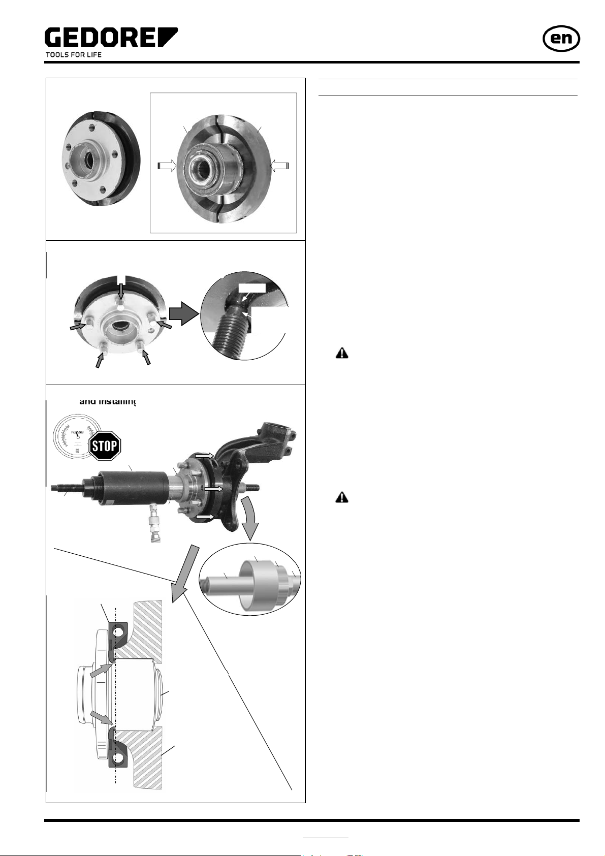
The KL-0041-44 Cwheel bearing tool enables the quick and
safe installation of wheel hub bearing units without the risk of
damaging them.
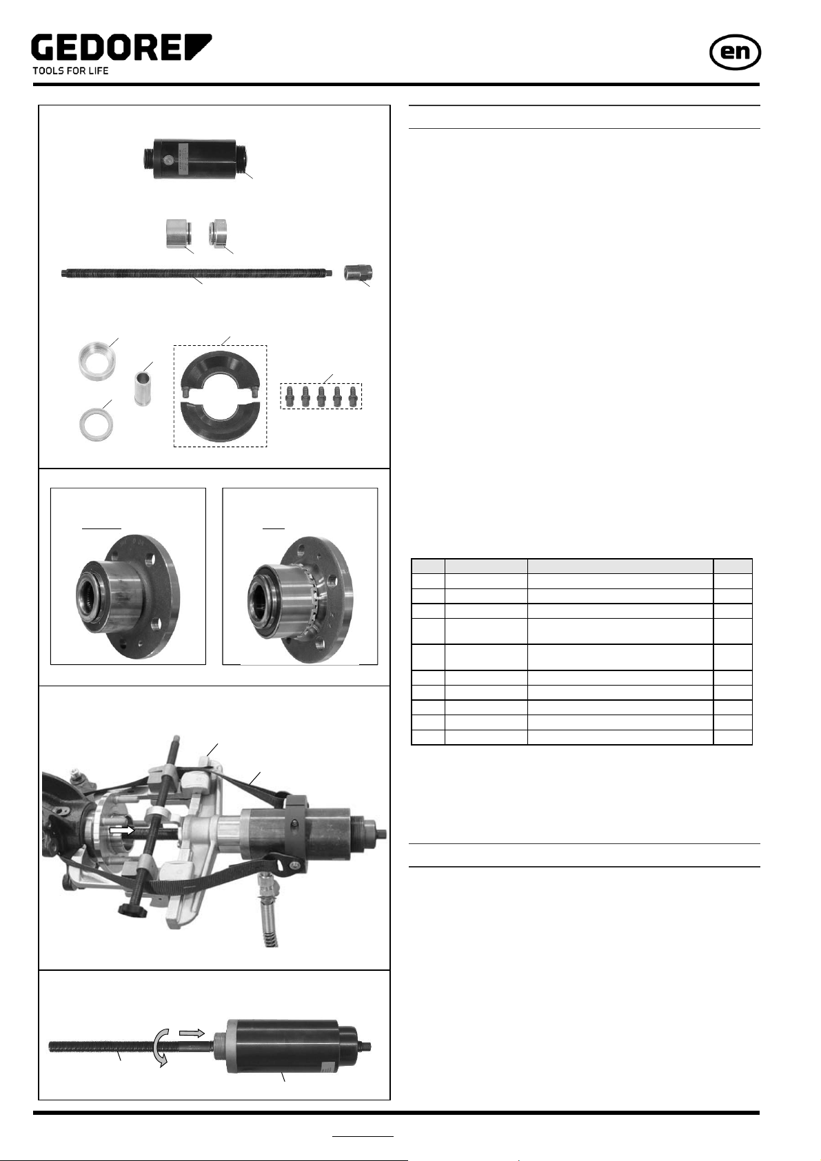
Due to the particular design of the wheel hub bearing units,
conventional installation by means of a thrust piece under a
workshop press or by using standard wheel bearing tools is no
longer feasible. This is because, with this type of bearing, the
outer bearing race is covered by the wheel hub. GEDORE
Automotive have now come up with a solution to this problem
with the specifically designed clamping shells which are
mounted against the wheel bearing outer race behind the wheel
hub, thus allowing for professional installation of the wheel hub
bearing units.
The clamping shells feature a securing collar designed to ensure
that wheel hub bearing units without snap ring are pressed in
completely/into deepened position.
For the removal of wheel hub bearing units, the wheel hub puller
KL-0041-38 is needed.
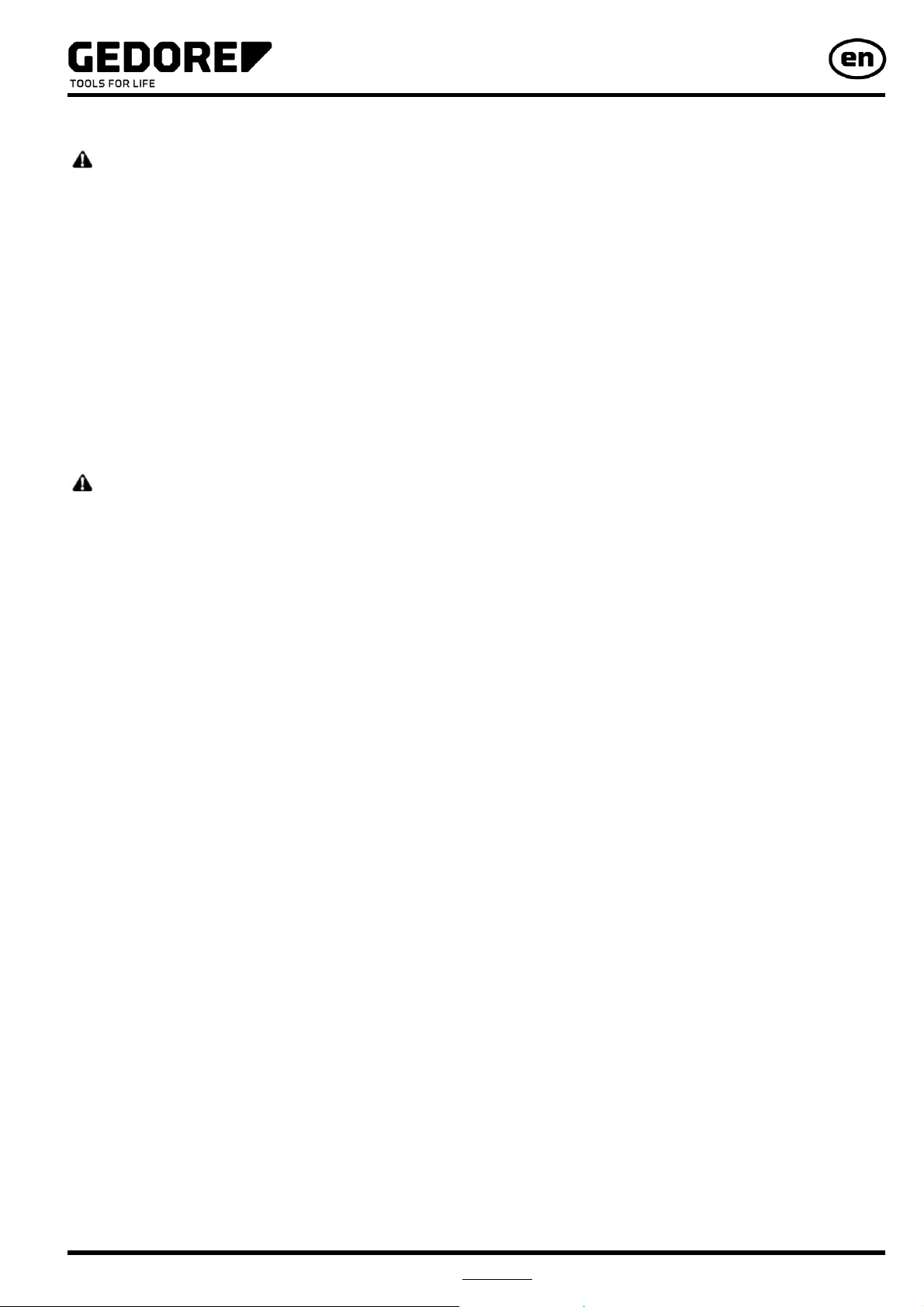
2.2 Scope of Delivery:
Pos. Part No. Description Qty
1 KL-0040-2500 Hydraulic Cylinder (17t) 1
2 KL-0040-3009 Clamping Nut, M20 1
3 KL-0039-1920-1 Pull Spindle, M20 1
4 KL-0039-1002 Retaining Adaptorwith O-Rings,
for Clamping Nut and Pressure Spindle 1
5 KL-0039-1003 Retaining Adaptor with O-Rings, for
Hydraulic Cylinder 1
6 KL-0041-4400 C Clamping Shells (Pair), Ø 72mm 1
7 KL-0041-3931 Pressure Screw, M14x1.5 5
8 KL-0039-1802 CentringSleeve, long, Ø 27.4mm 1
9 KL-0039-1265 Pressure Ring, Ø 65mm 1
10 KL-0039-1674 Pressure-/Support Sleeve, short, Ø 74mm 1
2.3 Technical Data
Maximum load capacity of the pull spindle: ......................... 20t
Maximum load capacity of the hydraulic cylinder:................ 17t
Weight: .......................................................................... 15.8kg
3. Preparatory Work
Before the first commissioning of the wheel bearing tool, check
and confirm you have all the parts listed in the scope of delivery.
Then, read and follow the mounting instructions.
3.1 Checking the Delivery.
3.2 Preparing the Vehicle.
1. Loosen and/or remove components as necessary.
Remove wheel hub bearing unit using the KL004138 wheel
hub puller (accessory). (Fig. 1)
Note: Secure tool with safety belt KL-0040-2590
(accessory) to prevent it from falling.
3.3 Preparing the Tool.
1. Screw pull spindle “3“ into hydraulic cylinder “1“. (Fig. 2)
KL-0041-44 C
Wheel Hub Bearing Unit:
Fig. 1: Removing the wheel hub bearing unit.
Fig. 2: Screwing the pull spindle into hydraulic cylinder.
KL-0041-38 (accessory)
KL-0040-2590 (accessory)
1
3
10
9
8
7
1
6
3 2
5 4
Wheel hub bearing unit
without snap ring
Wheel hub bearing unit
with snap ring

7
Chapter 4 0041-44Ce160604.docx hu-gm
© Copyright by GEDORE Automotive GmbH, Germany
Instruction Manual
4. Wheel Hub Bearing Unit Installation
The following instructions describe the procedure of installing a
wheel hub bearing unit at the front axle.
Installing the Wheel Hub Bearing Unit
1.
ATTENTION
Risk of damage to clamping shells “6“ and wheel hub
bearing unit.
Make sure that clamping shells “6“ are properly seated on
the wheel hub bearing unit.
Mount clamping shells “6“ to wheel hub bearing unit as
shown in Fig. 3.
2. Screw pressure screws “7“ evenly into wheel hub until the
non-threaded end of pressure screws “7“ completely
engages the groove of clamping shells “6“. Then, tighten
screws evenly in a crosswise sequence. (Fig. 4).
Note: Use a vernier calliper to check that pressure screws
“7“ are level with each other if necessary.
3.
CAUTION
A falling tool can cause injuries.
Use safety belt KL-0040-2590 to prevent tool from falling.
Always wear safety shoes/boots.
Mount tool to steering knuckle as shown in Fig. 5.
4. Connect hydraulic cylinder “1“ to hydraulic pump
(accessory).
5.
DANGER
When installing the wheel hub bearing unit, there is a risk
that pull spindle “3“ could break and fall to pieces. This will
lead to parts becoming projectiles.
Observe and do not exceed the maximum load capacity of
pull spindle “3“ and hydraulic cylinder “1“.
Use hydraulic pump with pressure gauge KL-0040-2529.
Only use the original spare parts from GEDORE
Automotive.
Always keep all parts of your body away from the axial
extension of the pull spindle.
Operate hydraulic pump and install wheel hub bearing unit.
(Fig. 5)
During the installation process, read and observe the force
indicated on the pressure gauge of the hydraulic pump.
Stop the installation process as soon as the wheel hub
bearing unit is correctly positioned.
Note: With wheel hub bearing units featuring a snap ring,
make sure that the snap ring engages completely!
6. Remove tool from steering knuckle. Check the position of the
wheel hub bearing unit and reassemble the vehicle
according to the manufacturer's directions and instructions.
Fig. 3: Mounting the clamping shells.
Fig. 4: Mounting the pressure screws.
Fig. 5: Mounting the tool to steering knuckle
and installing the wheel hub bearing unit.
6 6
7
7
7
7
Screw pressure screws “7“ evenly
into wheel hub.
Groove
Non-threaded
end of
pressure screw
7
17t
2
4
10
8
1 9
3
5
Pair of clamping shells
with securing collar “9“
Steering knuckle
Wheel hub
bearing unit
(without snap ring)

8
Chapter 4
0041-44Ce160604.docx hu-gm © Copyright by GEDORE Automotive GmbH, Germany
Instruction Manual
5. Care and Storage
ATTENTION Petroleum ether and chemical solvents can damage plastic
parts. Always clean all parts after their use with a clean cloth only.
In order to protect against corrosion, lightly lubricate all metal parts after
their use with oil and store them in a clean and dry place.
6. Accessoires :
KL-0215-35 M25 - Hydraulic Hand Pump
The hydraulic hand pump KL-0215-35 M25 is used to drive the hydraulic
cylinder KL-0040-2500.
KL-0040-2590 - Safety Belt
By fastening the safety belt KL-0040-2590 to the vehicle and the KL-
0040-2500 hydraulic cylinder, the latter is prevented from falling.
7. Maintenance and Repair by the GEDORE
Automotive Service Centre.
For safety reasons, as soon as damage is noticed on the wheel bearing
tool, immediate steps must be taken to prevent it from being used. For
professional inspection and repair of the wheel bearing tool, please
contact the GEDORE Automotive Service Centre.
Address:
GEDORE Automotive GmbH
Breslauerstraße 41
DE-78166 Donaueschingen
Phone: 0771 83 22 371
For additional information concerning the use of our wheel bearing tool,
please contact the GEDORE Automotive Service Centre.
8. Spare Parts List
Pos. Part No. Description Qty
- KL-0041-44 C Wheel Bearing Tool with 17t Hydraulic
Cylinder, Polo, Bearing Ø 72mm 1
composed of:
1 KL-0040-2500 Hydraulic Cylinder (17t) 1
- KL-0041-440 C
Wheel Bearing Tool without
17t Hydraulic Cylinder,
Polo, Bearing Ø 72mm
1
Pos. Part No. Description Qty
- KL-0041-440 C
Wheel Bearing Tool without
17t Hydraulic Cylinder,
Polo, Bearing Ø 72mm
1
composed of:
2 KL-0040-3009 Clamping Nut, M20 1
3 KL-0039-1920-1 Pull Spindle, M20 1
4 KL-0039-1002 Retaining Adaptor with O-Rings,for
Clamping Nut and Pressure Spindle 1
5 KL-0039-1003 Retaining Adaptor with O-Rings, for
Hydraulic Cylinder 1
- KL-0041-441 C Upgrade Kit, Polo, Bearing Ø 72mm 1
Pos. Part No. Description Qty
- KL-0041-441 C Upgrade Kit, Polo, Bearing Ø 72mm 1
composed of:
6 KL-0041-4400 C Clamping Shells (Pair), Ø 72mm 1
7 KL-0041-3931 Pressure Screw, M14x1.5 5
8 KL-0039-1802 CentringSleeve, long, Ø 27.4mm 1
9 KL-0039-1265 Pressure Ring, Ø 65mm 1
10 KL-0039-1674 Pressure-/Support Sleeve, short, Ø 74mm 1
9. Environmentally Safe Disposal
Recycle/dispose of wheel bearing tool and its packaging material in
compliance with the legal rules and regulations in force.
Fig. 6: Accessory: KL-0215-35 M25
Fig. 7: Accessory: KL-0040-2590
Fig. 8: Spare Parts: KL-0041-44 C
KL-0041-440 C
KL-0041-441 C
10
9
8
7
1
6
3 2
5 4
This manual suits for next models
2
Table of contents
Other Gedore Tools manuals
Popular Tools manuals by other brands

Tohnichi
Tohnichi ProTork CPT20X10D-G operating instructions

BorMann
BorMann BWR5123 user manual

XPOtool
XPOtool 60326 Operation manual

Paslode
Paslode IM350+ Lithium General safety instructions

Partex
Partex PHCT400-Kit SAFE OPERATION & MAINTENANCE INSTRUCTIONS

SUHNER ABRASIVE
SUHNER ABRASIVE LBC 16-TOP Technical document