Genie GSD106 User manual

GSD106
10x Optical High Speed PTZ Dome Camera
User Manual

3
Contents
Chapter 1 Product Overview................................................................................................................................. 1
I. Performance Features...................................................................................................................................... 1
II. Functions......................................................................................................................................................... 1
Chapter 2 Dome Wiring and Setup....................................................................................................................... 2
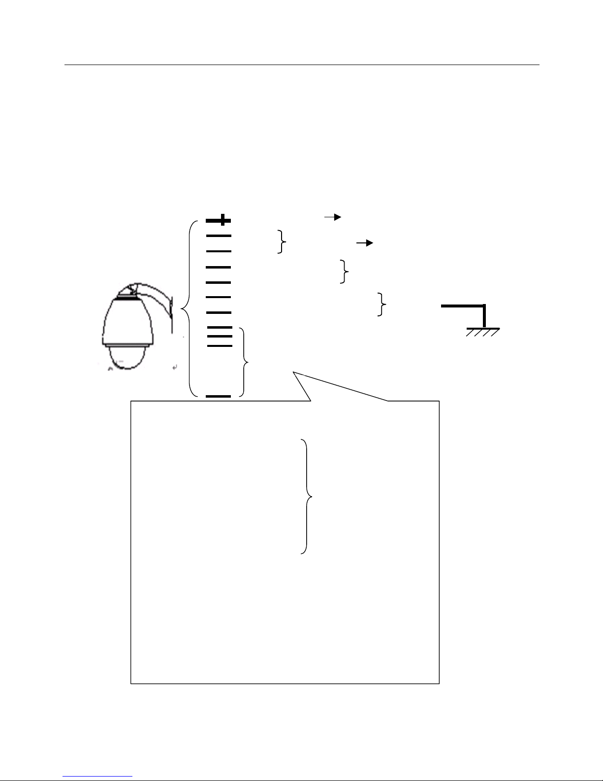
I. Wiring the Dome............................................................................................................................................... 2
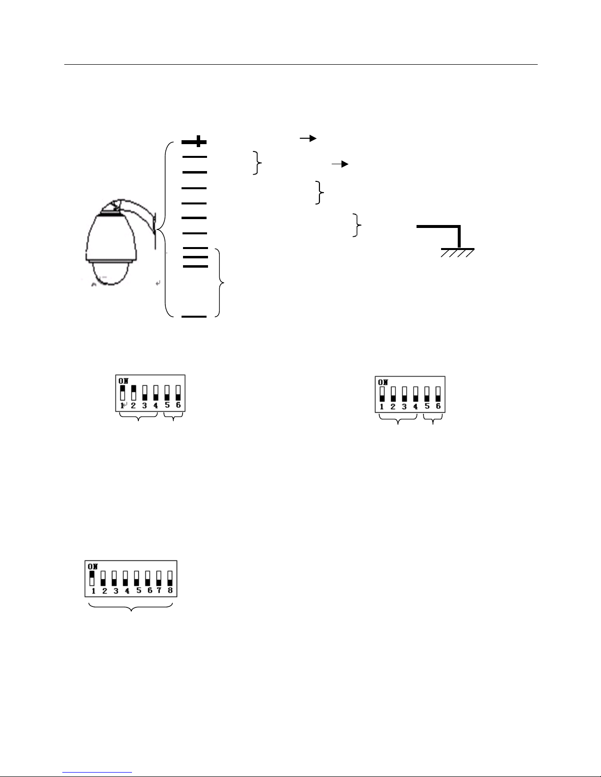
II. Setting the Device Communications ............................................................................................................... 3
Chapter 3 Quick Operating Guide ........................................................................................................................ 5
I. Wiring . ............................................................................................................................................................. 5
II. Setting the Protocol and Baud Rate. ............................................................................................................... 5
III. Setting the Device Address. ........................................................................................................................... 5
IV. Installing the Camera. .................................................................................................................................... 5
V. Connecting the Power..................................................................................................................................... 6
VI. Controller Setting ........................................................................................................................................... 6
VII. Start Testing.................................................................................................................................................. 6
VIII. Complete the Test (Summary)..................................................................................................................... 6
Chapter 4 Operation Menu .................................................................................................................................... 8
I. Operating Instructions ...................................................................................................................................... 8
II. Menu Tree List. ............................................................................................................................................... 9
1.Language Options .................................................................................................................................. 10
2.Display Options....................................................................................................................................... 10
3.Control Options....................................................................................................................................... 14
4.System Options ...................................................................................................................................... 16
5.Camera Options...................................................................................................................................... 18
6.Function Programming ........................................................................................................................... 24
7. User Admin ............................................................................................................................................ 30
8. Date/Time .............................................................................................................................................. 31
Chapter 5 Shortcut Operations and Specification............................................................................................ 34
Chapter 6 Main Technical Parameters ............................................................................................................... 36

1
Chapter 1 - Product Overview
I. Performance Features
1. Dome Address from 1 - 255
2. Multiple protocols and auto protocol negotiation
3. Pan 360°continuous rotation
4. Tilt 90°action plus 2°angle adjustment
5. Pan manual operation speed ranging from 0.1°to 300°/S
6. Tilt manual operation speed ranging from 0.1°to 120°/S
7. 255 Preset positions
8. The maximum Preset running speed, when called, can reach 400°/S with an accuracy of ±0.1°
9. Power supply AC24V, 2A
10. Easy installation interface
11. IP66 environmental protection
12. RS-485 transmission
13. Transmission speed, baud rate selectable
II. Functions
1. Multi-language OSD menu and display
2. Display for camera name, operating position and angle
3. Crosshair operating function
4. Six Tour operations with 2 minutes recording per Tour
5. Eight groups of programmable vector scans
6. Vertical auto flip with 10°automatic forward tracing
7. Eight programmable sectional mask zones
8. Eight programmable sectional display sectors
9. The dome returns to run mode after self-test, or no communication received
10. Image frame freeze
11. Operation resume function
12. Intelligent manual scan function
13. Intelligent power off. Data held in real time memory and resumes operation on power on
14. Highly efficient 3-dimensional scan
15. Proportional zoom
16. User management and operation authorisation
17. Time & Date Display
18. Assignment programming
19. Timer for startup and shutdown
20. Alarm and warning mechanism
21. Real-time operating temperature display
22. Temperature alarm and high temperature shutdown

2
Chapter 2 - Wiring and Setup of Dome System
I. Wiring the Dome
1.Basic System Connection
The basic system connections are shown below. When using this product for the first time, please read and
carefully follow this electrical wiring schematic as incorrect wiring may lead to permanent damage of the dome or
damage of other attached equipment.
Yellow-Green
Yellow-Green
Orange RS485A (+)
Yellow RS485B (-)
BNC Video Output
Red
Black
Description for Alarm Function:
No.1 Alarm Input: Red and White
No.2 Alarm Input: Yellow and White
No.3 Alarm Input: Grey and White
No.4 Alarm Input: Orange and White
No.5 Alarm Input: Brown
No.6 Alarm Input: Green and White
No.7 Alarm Input: Brown and White
No.8 Alarm Input: Blue and White
No.8 Alarm Input: Grey and White
Alarm Input Public Terminal(COM1): Black/White
No.1 Alarm Constant ON Output(NO1): Blue and Green
No.1 Alarm Output Public Terminal(COM1): Blue
No.2 Alarm Constant ON Output(NC2): Brown and Green
No.2 Alarm Output Public Terminal(COM2): Green
The brown stranded
wire with alarm input wire
is the alarm system ground
Connected to
Ground
Controller of
the Dome
Power Supply of Dome
Display
External Connection for Alarm Input/Output
AC24V Input

3
2. Multi Dome Connection
When connecting multiple domes together you can embed them in a multi-device system with auxiliary
connection to devices, such as surge protectors, video matrixes, DVR’s and alarm boxes.
AC24V: Power supply for the dome, which converts 220V/50HZinput to an AC24V output.
RS-485 Bus: Is for the control signal (RS-485 signal) output of a controller - connected to the communication
input terminals of the control cable of each dome.
Video: Is for image signal output of each dome (can be directly output to video equipment, such as a monitor,
DVR or video matrix.
II. Setting the Device Communications
Before installation and use, the settings for the communication protocol and transmission speed (baud rate)
should match those used by the control system.

4
1.Setting the dome’s protocol and baud rate.
Note: The protocol and baud rate
of dome should match with those
used by the controller. The dome needs to be restarted after revision.
2. Address setting of dome device
Dome device range: 1~255
On/Off
Protocol
1st
digit
2nd
digit
3rd
digit
4th
digit
5th
digit
6th
digit
PELCO-D
ON
ON
OFF
OFF
**
**
PELCO-P
OFF
ON
OFF
OFF
**
**
DYNACOLOR
ON
OFF
OFF
OFF
**
**
ULTRACK
OFF
OFF
ON
OFF
VICON
OFF
OFF
OFF
OFF
**
**
On/Off
Baud Rate
5th
digit
6th
digit
2400
OFF
OFF
4800
OFF
ON
9600
ON
OFF
19200
ON
ON
协
议
设
置
波
特
率
设
置
拔
码
开
关
This figure shows the setting PELCO-D
protocol and baud rate of 2400bps
Address setting address
for dome (this figure shows the
dome address of dome as 1)
On/Off
Setting method: The sum of switch numbers when they
are in the ON position is the address of the dome.
Calculation example of a dome address:
(2+4+16=22)the address is 22.
1
2
4
8
16
32
64
128
Matching numbers
24 16
On/Off and
matching numbers
On/Off
switch
Baud Rate Setting
Protocol Setting

5
Chapter 3 - Quick Operating Guide
I. Wiring
II. Setting Protocol and Baud Rate
The figure shows: Protocol: PELCO-D The figure shows: Auto detection protocol.
Baud rate: 2400 bps Baud rate: 2400bps
(Refer to detailed parameters in the next chapter)
III. Setting Dome Address
The figure shows: A Dome Address of 1
(Refer to detailed parameters in the next chapter)
This dip switch is located on the PCB in the dome
IV. Install Camera
Note: 1.Do not connect the camera and dome with FFC in an incorrect manner.
2.The installation fixing holes of for different camera may differ.
Set address for Dome
Protocol
Setting
Baud Rate
Setting
Protocol
Setting
Baud Rate
Setting
Turn the power Off when setting, and restart the dome after revision
Orange RS485A (+)
Yellow RS485B (-)
Controller of
the Dome
Yellow-Green Interphase Colour
BNC Video Output
Red
Black
External Connection for Alarm Input/Output
AC24V Input
Connected to
Ground
Power Supply of Dome
Display

6
V. Connect the Dome Power
When power is applied to the Dome the product enters a self-test routine which outputs the video image to an
attached monitor.
Note: When the dome is self-testing it is normal to hear sounds made by the Dome’s pan and tilt motors.
VI. Controller
Set the communication protocol, baud rate and address of the keyboard controller. These must be identical to
those used for the Dome.Please refer to the Keyboard Controller instruction manual.
Note: If the protocol for the Dome is set to auto detection, the protocol for the Keyboard Controller can be set
arbitrarily, but the baud rate must be set identical with that of the Dome.
VII. Start Testing
When the above are complete, the Dome testing can be started.
1. Direction Control Test 2. Zoom Control Test
The up, down, left and right directions of the The Camera Zoom can be controlled using the
Dome can be controlled by using the Joystick zoom function, or by the TELE (Zoom in)
Keyboard Controller, as indicated above. and WIDE (Zoom out) keyboard buttons.
VIII. Complete the Test
1.If the test performance is normal it indicates the system is operating normally. Please do not make any
changes to the wiring and or settings. To do so may cause faults and/or unnecessary damage and loss.
2.If the test performance is abnormal, or only one test is performing normally, please check the wiring (items 1
and IV) and the settings (item II, III and VI).
Up
Down
Left
Right
Zoom In
Zoom Out
Rotate

7

8
Chapter 4 – Operation Menu
I. Operating Instructions
<1>. Menu Operation Instructions
1. Input a Tilt movement command for cursor movement and option selection, namely the controller moves the
Joystick up and down; hereinafter called Joystick Up/Down
2. Input a Pan movement command for entering into an option or for changing a setting value, namely the
controller moves the Joystick left and right; hereinafter called Joystick Left/Right
3. Input an Iris Open command for confirming setup or for changing value(s), namely the controller initiates an
IRIS OPEN command; hereinafter called Press IRIS OPEN
4. Input an Iris Close command to cancel a setting or to Exit, namely the controller initiates an IRIS CLOSE
command; hereinafter called Press IRIS CLOSE
<2>. To Input a Numeric Value
1. Move the Joystick Left/Right for the cursor to select the numeric value to be entered.
2. Press IRIS OPEN to confirm, and the number selected is displayed; as indicated in the pictures below.
3. Move the Joystick Left/Right to select the next number to be entered.
4. Press IRIS OPEN to confirm, the selected number is displayed in the corresponding data bit.
5. Press IRIS CLOSE to confirm and exit when complete.
.
<3>. To Input a Character
1. Move the Joystick Left/Right for the cursor to select the character to be entered.
2. Press IRIS OPEN to confirm, and the character selected is displayed; as indicted in the pictures below.
3. Move the Joystick Left/Right to select the next character to be entered.
4. Press IRIS OPEN to confirm, the character is displayed in the corresponding data bit.
5. Input other characters, as required by repeating the above procedure.
6. Press IRIS CLOSE to save and exit when complete.
1~255
001
0 1 2 3 4 5 6 7 8 9
IRIS CLOSE when done
1~255
001
0 1 2 3 4 5 6 7 8 9
IRIS CLOSE when done

9
<4>. Logon
1. Invoke Preset 92 preset for the Administrator logon.
Invoke Preset 93 preset for the Operator logon.
Factory Set Password: Administrator: 000000 Operator: 111111
Note: The Administrator password should be changed and be kept secure.
2. Move the cursor after entering the Please enter the Password interface. Select the bit to be entered.Then
press IRIS OPEN to enter the alphanumeric and press IRIS OPEN to confirm. Input the correct 6 digit
passwords as shown above.
After the input is complete, press IRIS CLOSE. Error will be prompted on screen if the input is wrong. The
screen goes directly into the window to be operated if the input is correct.
II. Menu Tree List
<1> Main Menu. Press 90+PRE to enter the Main Menu.
——————
IRIS CLOSE when done
0 1 2 3 4 5 6 7 8 9 A B C D E F G H
I J K LM NOPQ R S T UV W X Y Z
IRIS OPEN when done
IRIS CLOSE to exit
PARK——
IRIS CLOSE when done
CAMERA OPTIONS
1.ZOOM AND FOCUS
2.CAMERA EXPOSURE
3.MASK ZONE
4.MASK COLOR
5.OTHERS
0123456789ABCD
EFGHIJKLMNOPQ
RSTUVWXYZ
PLS enter the password
******
IRIS CLOSE when done
1.LANGUAGE ENGLISH
2.DISPLAY OPTIONS
3.CONTROL OPTIONS
4.SYSTEM OPTIONS
5.CAMERA OPTIONS
6.FUNCTION PROGRAMMIING
7.USER ADMIN
8.DATE/TIME

10
<2> All sub-menus can be seen in this tree list
1.Language Options
<<Language Options Jovstick Left/Right to select
2.Display Options
<<Display Options Press IRIS OPEN or Jovstick Left/Right to enter
2.1.Preset Setup
<<Preset Setup Options
①Number 1
<<Preset Number Selection Press IRIS OPEN or Jovstick Left/Right to enter
<<The default number after entering is 001 (hundred bit/ten
bit/single bit). Joystick Left/Right to select the Preset position and
press IRIS OPEN to confirm. Joystick Left/Right again to select
numbers (0~~9). Press IRIS OPEN to confirm the selection.
Press IRIS CLOSE to exit to the upper level menu when
programming is complete.
②Set Preset
<<Set Preset Press IRIS OPEN or Jovstick Left/Right to enter
Move the cursor to select the Preset position. Press IRIS CLOSE
to finalise your selection. The screen displays STORED and
returns to the previous menu.
③Call Preset
<<Call Preset Press IRIS OPEN or Joystick Left/Right to enter
Select the number to be called. Joystick Up/Down to select the Call Preset Menu. Joystick Left/Right or
press IRIS OPEN and the camera moves to corresponding Preset number.
1~255
001
↑
0 1 2 3 4 5 6 7 8 9
IRIS CLOSE when done
STORED
(English/Espanol/Polski)

11
④Delete Preset
<<Delete Preset Press IRIS OPEN or Joystick Left/Right to enter
Select the number needed to be deleted from the number options.Move the cursor to Delete Preset.
Joystick Left/Right or press IRIS OPEN to enter into the Delete Preset menu. Press IRIS OPEN to confirm
the selection or IRIS CLOSE to cancel the selection and exit.
<<Reminder: Are you sure you want to delete the Preset?
Press IRIS OPEN to confirm
Press IRIS CLOSE to exit to the upper level menu.
⑤Name _ _ _ _ _ _ _ _
<<Edit the Preset Name Press IRIS OPEN or Joystick Left/Right to enter
Press IRIS OPEN to enter
⑥Name Display ON
<<Name Display ON/OFF Joystick Left/Right to select
IRIS CLOSE to exit
2.2.Sector Setup
<<Sector Setup Press IRIS OPEN or Joystick Left/Right to enter
Are you sure to do this?
IRIS OPEN to confirm
IRIS CLOSE to cancel
_ _ _ _ _ _ _ _
↑
IRIS CLOSE when done
<<Joystick Left/Right when programming to select the Preset and
press IRIS OPEN to confirm.
Joystick Left/Right to select (0~~9 or A~~Z). Press IRIS OPEN to
confirm selection.
Press IRIS CLOSE to exit to the upper level menu when
programming is complete.
0 1 2 3 4 5 6 7 8 9 A B C D E
F G H IJ K L M N O P Q R S
TU V W X Y Z _
IRIS OPEN when done
IRIS CLOSE to exit

12
①Number 1
<<Number Selection (1 ~ 8) Joystick Left/Right to select
②Name _ _ _ _ _ _ _ _
<<Name Editing Press IRIS OPEN or Joystick Left/Right to enter
Press IRIS OPENto enter
③Pan Start Pos 0.0
④Pan End Pos 0.0
⑤Tilt Start Pos 0.0
⑥Tilt End Pos 0.0
_ _ _ _ _ _ _ _
↑
IRIS CLOSE when done
<< Joystick Left/Right when programming to select the
Preset and press IRIS OPEN to confirm.
Joystick Left/Right to select (0~9 or A~Z). Press IRIS OPEN
to confirm selection.
Press IRIS CLOSE to exit to upper level menu when
programming is complete.
<< Setup Tilt start point. Press IRIS OPEN or Joystick Left/Right to
enter.Use joystick to capture Tilt start point. Press IRIS CLOSE to
confirm and exit to upper level menu.
<< Setup Tilt end point. Press IRIS OPEN or Joystick Left/Right to
enter. Use joystick to capture Tilt end point. Press IRIS CLOSE to
confirm and exit to upper level menu.
0123456789ABCDE
FGHIJKLMN
↑
OPQRSTUVWXYZ _
IRIS OPEN when done
IRIS CLOSE to exit
<< Setup Pan end point. Press IRIS OPEN or Joystick
Left/Right to enter. Use joystick to capture Pan end point.
Press IRIS CLOSE to confirm and exit to upper level menu.
<< Setup Pan start point. Press IRIS OPEN or Joystick
Left/Right to enter.Use joystick to capture Pan start point.
Press IRIS CLOSE to confirm and exit to upper level menu.

13
⑦Name Display ON <<Sector Name Display ON/OFF
Joystick Left/Right to select
IRIS CLOSE to exit
2.3. Co-ordinates ON
<<Co-ordinates display On/Off Joystick Left/R ight to select
2.4. Crosshairs OFF
<<Crosshairs On/Off Joystick Left/Right to select
2.5.Start-Up Scr Msg ON
<<Start-Up screen message display On/Off Joystick Left/Right to select
2.6. OSD Style NORMAL
<<The style of the OSD menu is Nomal Joystick Left/Right to select
2.7.Dome Name Setup
<<Setup the Name of the Dome Joystick Left/Right to select
Press IRIS OPEN to enter
Press IRIS CLOSE to exit
1.DOME NAME
2.NAME DISPLAY OFF
_ _ _ _ _ _ _ _
↑
IRIS CLOSE when done

14
3.Control Options
<<Control Options Press IRIS OPEN or Joystick Left/Right to enter
3.1.Set Pan and Tilt
<<Dome Pan/Tilt Setup Press IRIS OPEN or Joystick Left/Right to enter
①Pan Reverse OFF << Pan Reverse ON/OFF Joystick Left/Right to select
②Tilt Reverse OFF << Tilt Reverse ON/OFF Joystick Left/Right to select
③+2 Tilt Limit OFF <<+2 Tilt Limit ON/OFF Joystick Left/Right to select
④Find Home On Sta. ON << Find Home on Start ON/OFF Joystick Left/Right to select
IRIS CLOSE to exit
3.2.Set Default Function
<<Set Home Position Press IRIS OPEN or Joystick Left/Right to enter
①Default Function P/V/T
<<Select default function (Preset/Tour/PTZ) Press IRIS OPEN or Joystick Left/Right to enter
②Number 1
<< Function number selection Press IRIS OPEN or Joystick Left/Right to enter
③Delay 60
<<Time delay setting (in seconds) Press IRIS OPEN or Joystick Left/Right to enter
1~255
001
0123456789
IRIS CLOSE when done
1~999
060
0123456789
IRIS CLOSE when done
<< Joystick Left/Right when programming to select the Preset.
Press IRIS OPEN to confirm. Joystick Left/Right to select (0~~9).
Press IRIS OPEN to confirm selection. Press IRIS CLOSE to exit
to upper level menu when programming is complete.
<< Joystick Left/Right when programming to select the
Preset. Press IRIS OPEN to confirm. Joystick Left/Right to
select (0~9). Press IRIS OPEN to confirm. Press IRIS
CLOSE to exit to upper level menu when programming is
complete.

15
④Operation OFF
<<Default function ON/OFF Joystick Left/Right to select
IRIS CLOSE to exit
3.3. Speed Limit ON
<<Operation speed limit ON/OFF Joystick Left/Right to select
3.4. Auto Flip ON
<<Auto flip ON/OFF Joystick Left/Right to select
3.5. Auto Focus PTZ
<<Auto focus options PTZ/OFF/Z Joystick Left/Right to select
3.6. Auto AE PTZ
<<Auto AE option PTZ/OFF/Z Joystick Left/Right to select
3.7. VectorScan AF OFF
<<VectorScan auto focus control ON/OFF Joystick Left/Right to select
3.8. VectorScan Still OFF
<< VectorScan Still ON/OFF Joystick Left/Right to select
IRIS CLOSE to exit

16
4. System Options
<< System Options Press IRIS OPEN or Joystick Left/Right to enter
Function Description: This option is used for data information management of the dome. The operating
authority on this option is limited to the Administrator (with the correct password).
4.1. Clear Memory
<<Clear data in the memory Press IRIS OPEN or Joystick Left/Right to enter
4.2. Restore Default Settings
<<Restore default settings Press IRIS OPEN or Joystick Left/Right to enter
4.3. Colour System PAL/NTSC
<< PAL/NTSC switch Joystick Left/Right to select
4.4. Restart the Dome
<< Restart the Dome
Are you sure to do this?
IRIS OPEN to confirm
IRIS CLOSE to cancel
Are you sure to do this?
IRIS OPEN to confirm
IRIS CLOSE to cancel
<<Reminder: Are you sure you want to do this?
Press IRIS OPEN to confirm.
Press IRIS CLOSE to exit and return to upper level menu.
<< Reminder: Are you sure you want to do this?
Press IRIS OPEN to confirm.
Press IRIS CLOSE to exit and return to upper level menu.
Are you sure to do this?
IRIS OPEN to confirm
IRIS CLOSE to cancel
<<Reminder: Are you sure you want to do this?
Press IRIS OPEN to confirm.
Press IRIS CLOSE to exit and return to upper level menu.

17
4.5. Dome Information
<<Dome Information Press IRIS OPEN or Joystick Left/Right to enter
Press IRIS CLOSE to exit
4.6.Communications Settings
<< Comm Setings Joystick Left/Right to select
①COMM MODE HW/SW
<< Hardware Address/Software Address Joystick Left/Right to select
②Dome ID 1
<< ID Adress of the Dome Joystick Left/Right to select. Can only be set by the R/W mode
of the comm setting
③Baud Rate 1
<< Baud Rate of the Dome Joystick Left/Right to select. Can only be set by the R/W mode
of the comm setting
④INPUT SN Joystick Left/Right to select
⑤SN
<<Serial Number N/A
4.7 Camera Memory OFF/ON
<< Automatic defaults to the last model Joystick Left/Right to select
of the Camera module
Camera: FCB-EX1020P
Protocol: Pelco-D
Baud Rate: 2400
Dome No.:1
COMM MODE: HW
SN: 10000084
IRIS CLOSE to exit
<<Type of Camera module
<<Control Protocol
<<Baud Rate
<<Dome Number
<<Communication Mode
<<Serial Number
<<Press IRIS CLOSE to exit and return to upper level
menu.
<< Press CLOSE to exit and return to upper stage
menu.

18
5.Camera Options
<< Camera Options Press IRIS OPEN or Joystick Left/Right to enter
5.1. Zoom and Focus
<< Zoom and Focus Press IRIS OPEN or Joystick Left/Right to enter
①Zoom Speed 7
<< Zoom Speed 1~8Joystick Left/Right to select
②Digital Zoom OFF
<<Digital Zoom ON/OFF Joystick Left/Right to select
③AF Sensitivity High
<< AF Sensitivity High/Low Joystick Left/Right to select
Press IRIS CLOSE to exit
5.2. Camera Exposure
<< Camera Exposure Press IRIS OPEN or Joystick Left/Right to enter
①AE Mode AUTO
<<AE Mode AUTO/Manual/Shutter/Iris/Bright Joystick Left/Right to select
②Slow Shutter ON
<< Slow Shutter ON/OFF Joystick Left/Right to select
③Shutter Speed AUTO
<< Shutter Speed AUTO Joystick Left/Right to select
Is adjustable under AE mode Manual or Shutter.
④Iris Level AUTO
<< Iris Level AUTO Joystick Left/Right to select
Is adjustable under AE mode Manual or Iris.
⑤AGC Level AUTO
<< AGC Level AUTO Joystick Left/Right to select
Is adjustable under AE mode Manual.
⑥Brightness Level AUTO
<< Brightness Level AUTO Joystick Left/Right to select
Is adjustable under AE mode Bright.
⑦Spot AE OFF
<< Spot AE ON/OFF Joystick Left/Right to select
Press IRIS CLOSE to exit
Table of contents
Other Genie Security Camera manuals

Genie
Genie W70SBIR User manual

Genie
Genie PWIP4BVAF User manual

Genie
Genie DN83SPX/12 Manual

Genie
Genie GSDNR-6358 Manual

Genie
Genie GIP5NCMIR User manual

Genie
Genie TPH-4000P User manual

Genie
Genie WIP1VD User manual

Genie
Genie GAHDB21W User manual

Genie
Genie TPC 8922 Series User manual

Genie
Genie PWIPN2EB User manual

Genie
Genie Geniewatch NSD5451 User manual

Genie
Genie GAHD18IRPTZ User manual

Genie
Genie VRD73IR User manual

Genie
Genie WIPX8VDVAF5 User manual

Genie
Genie WISH96 Series User manual

Genie
Genie SSIP2DVAF User manual

Genie
Genie PWIPN2EBV User manual

Genie
Genie ZD2812IR User manual

Genie
Genie ZD2812WL User manual

Genie
Genie ZD5502 User manual