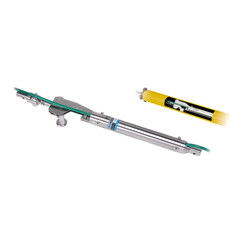
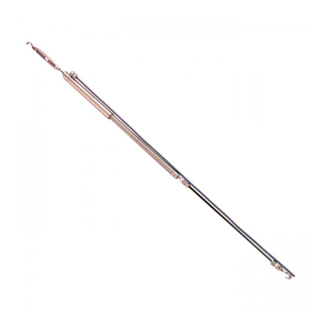
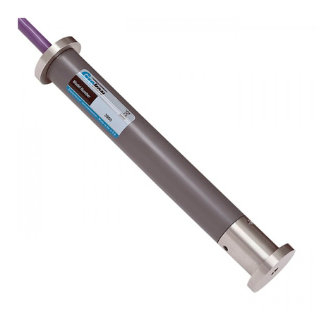
Geokon 4700 User manual

Instruction Manual
Model 4700
VW Temperature Gage
No part of this instruction manual may be reproduced, by any means, without the written consent of Geokon, Inc.
The information contained herein is believed to be accurate and reliable. However, Geokon, Inc. assumes no responsibility for
errors, omissions, or misinterpretation. The information herein is subject to change without notification.
Copyright © 1984-2018 by Geokon, Inc.
(Doc Rev H, 03/01/18)


Warranty Statement
Geokon, Inc. warrants its products to be free of defects in materials and workmanship, under
normal use and service for a period of 13 months from date of purchase. If the unit should
malfunction, it must be returned to the factory for evaluation, freight prepaid. Upon examination
by Geokon, if the unit is found to be defective, it will be repaired or replaced at no charge.
However, the WARRANTY is VOID if the unit shows evidence of having been tampered with
or shows evidence of being damaged as a result of excessive corrosion or current, heat, moisture
or vibration, improper specification, misapplication, misuse or other operating conditions outside
of Geokon's control. Components which wear or which are damaged by misuse are not
warranted. This includes fuses and batteries.
Geokon manufactures scientific instruments whose misuse is potentially dangerous. The
instruments are intended to be installed and used only by qualified personnel. There are no
warranties except as stated herein. There are no other warranties, expressed or implied, including
but not limited to the implied warranties of merchantability and of fitness for a particular
purpose. Geokon, Inc. is not responsible for any damages or losses caused to other equipment,
whether direct, indirect, incidental, special or consequential which the purchaser may experience
as a result of the installation or use of the product. The buyer's sole remedy for any breach of this
agreement by Geokon, Inc. or any breach of any warranty by Geokon, Inc. shall not exceed the
purchase price paid by the purchaser to Geokon, Inc. for the unit or units, or equipment directly
affected by such breach. Under no circumstances will Geokon reimburse the claimant for loss
incurred in removing and/or reinstalling equipment.
Every precaution for accuracy has been taken in the preparation of manuals and/or software,
however, Geokon, Inc. neither assumes responsibility for any omissions or errors that may
appear nor assumes liability for any damages or losses that result from the use of the products in
accordance with the information contained in the manual or software.

TABLE of CONTENTS
1. THEORY OF OPERATION ................................................................................................................................. 1
2. INSTALLATION.................................................................................................................................................... 1
3. READOUT PROCEDURES .................................................................................................................................. 1
4. DATA REDUCTION.............................................................................................................................................. 2
5. TROUBLE SHOOTING ........................................................................................................................................ 2
APPENDIX A. SPECIFICATIONS .......................................................................................................................... 2
APPENDIX B. TYPICAL CALIBRATION SHEET .............................................................................................. 3
APPENDIX C. THERMISTOR TEMPERATURE DERIVATION...................................................................... 4
APPENDIX D. HIGH TEMPERATURE THERMISTOR LINEARIZATION ................................................... 5
FIGURES
FIGURE 1-TYPICAL CALIBRATION SHEET..................................................................................................................... 3
TABLES
TABLE 1-SPECIFICATIONS ............................................................................................................................................ 2
TABLE 2-THERMISTOR RESISTANCE VERSUS TEMPERATURE ....................................................................................... 4
TABLE 3-THERMISTOR RESISTANCE VERSUS TEMPERATURE FOR HIGH TEMPERATURE MODELS................................ 5
EQUATIONS
EQUATION 1-TEMPERATURE ........................................................................................................................................ 2
EQUATION 2-RESISTANCE TO TEMPERATURE .............................................................................................................. 4
EQUATION 3-HIGH TEMPERATURE RESISTANCE TO TEMPERATURE............................................................................. 5

1
1. THEORY OF OPERATION
A tensioned steel wire is clamped axially inside a cylindrically shaped, stainless steel body and is
made to vibrate at its fundamental frequency by means of electrical pulses fed from a readout,
through ac cable, to an electronic coil and permanent magnet assembly mounted close to the
wire. Temperature changes cause the stainless steel body to expand and contract at a different
rate than the vibration wire. This causes a corresponding change in the wire tension and in its
vibrational frequency. Vibration of the wire in the permanent magnetic field induces an
alternating current in the electronic coil with the same frequency. The readout used to pluck the
wire is mow used to measure this frequency, which can then be related to the temperature by
means of a calibration factor supplied with each gage.
All components are made from stainless steel for corrosion protection. The gages are waterproof
and contain internal protection against lightning damage. Each gage also incorporates a
thermistor for use as a backup or as an independent check on the temperature reading.
The thermal response of the Model 4700 is quite slow; it is not suitable for the measurement of
rapidly changing temperatures. (See Appendix A for details.)
2. INSTALLATION
The Model 4700 Vibrating Wire Temperature Sensor are fully waterproof and can be installed
inside boreholes, buried in fill, or cast inside concrete with no particular requirements needed.
Preliminary readings should be taken to ensure that the sensor is functioning properly. Most
models incorporate a thermistor that can be used as a check on the vibrating wire readout.
3. READOUT PROCEDURES
Connect the black and red leads to the GK-403, GK-404 or GK-405 VW Readout Box and read
on channel B. If the GK-403, GK 404 or GK-405 Readout Box or 8600 Datalogger is used, the
thermistor readout can be displayed directly in °C.
The thermistor can be read on the green and white conductors using a digital ohmmeter in
conjunction with the conversion Table 2 in Appendix C. For High Temperature models, use
Table 3 in Appendix D. (Since the resistance changes with temperature are large, the effect of
cable resistance is usually insignificant. For long cables a correction can be applied, equal to 14.7
ohms per one thousand feet. Multiply this factor by two to account for both directions.)

2
4. DATA REDUCTION
The temperature (T) is given by the formula:
T = G (R1–R0) in degrees Centigrade
Equation 1 - Temperature
Where;
R0is the initial reading on channel B at 0 °C (from the calibration sheet).
R1is the subsequent reading on channel B
Gis the gage factor found on the calibration sheet. (A typical calibration sheet is shown in
Appendix B.)
For greater accuracy, use the polynomial equation found on the calibration sheet provided with
the instrument.
5. TROUBLE SHOOTING
Maintenance and troubleshooting of vibrating wire temperature sensors are confined to periodic
checks of cable connections and maintenance of terminals. The transducers themselves are
sealed and cannot be opened for inspection.
Normal resistance between black and red conduction is 180Ω(±5Ω), plus cable resistance of
14.7 Ωper one thousand feet. (Multiply this factor by two to account for both directions.)
Normal resistance between white and green conduction depends on the temperature. (See Table 2
in Appendix C. For High Temperature models, use Table 3 in Appendix D.). If the resistance
deviates from the norms, inspect the cable for damage.
APPENDIX A. SPECIFICATIONS
Standard Range
–20 °C to +80 °C
Optional Range
Any 200 °C span from –200 °C to +200 °C.
Resolution
0.034 °C (Approximate)
Accuracy1
±0.5°C
Response Time2
2.5 minutes
Thermal Equilibrium3
15 minutes
Frequency Range
1400 – 3500 Hz
Diameter
.75” (19.05 mm)
Length
5.125” (130.175 mm)
Weight
115 gm
Cable
Four conductor, shielded, 22 AWG
Table 1 - Specifications
1Established under laboratory conditions.
2Time required to reach 63.2% of an instantaneous temperature change.
3Maximum time required to reach thermal equilibrium.

3
APPENDIX B. TYPICAL CALIBRATION SHEET
Figure 1 - Typical Calibration Sheet

4
APPENDIX C. THERMISTOR TEMPERATURE DERIVATION
Thermistor Type: YSI 44005, Dale #1C3001-B3, Alpha #13A3001-B3
Resistance to Temperature Equation:
T= 1
A+B(LnR)+C(LnR)3-273.2
Equation 2 - Resistance to Temperature
Where;
T =Temperature in °C.
LnR =Natural Log of Thermistor Resistance
A =1.4051 ×10⁻³
B =2.369 ×10⁻⁴
C =1.019 ×10⁻⁷
Note: Coefficients calculated over the −50 to +150°C. span.
Ohms
Temp
Ohms
Temp
Ohms
Temp
Ohms
Temp
Ohms
Temp
201.1K
-50
16.60K
-10
2417
+30
525.4
+70
153.2
+110
187.3K
-49
15.72K
-9
2317
31
507.8
71
149.0
111
174.5K
-48
14.90K
-8
2221
32
490.9
72
145.0
112
162.7K
-47
14.12K
-7
2130
33
474.7
73
141.1
113
151.7K
-46
13.39K
-6
2042
34
459.0
74
137.2
114
141.6K
-45
12.70K
-5
1959
35
444.0
75
133.6
115
132.2K
-44
12.05K
-4
1880
36
429.5
76
130.0
116
123.5K
-43
11.44K
-3
1805
37
415.6
77
126.5
117
115.4K
-42
10.86K
-2
1733
38
402.2
78
123.2
118
107.9K
-41
10.31K
-1
1664
39
389.3
79
119.9
119
101.0K
-40
9796
0
1598
40
376.9
80
116.8
120
94.48K
-39
9310
+1
1535
41
364.9
81
113.8
121
88.46K
-38
8851
2
1475
42
353.4
82
110.8
122
82.87K
-37
8417
3
1418
43
342.2
83
107.9
123
77.66K
-36
8006
4
1363
44
331.5
84
105.2
124
72.81K
-35
7618
5
1310
45
321.2
85
102.5
125
68.30K
-34
7252
6
1260
46
311.3
86
99.9
126
64.09K
-33
6905
7
1212
47
301.7
87
97.3
127
60.17K
-32
6576
8
1167
48
292.4
88
94.9
128
56.51K
-31
6265
9
1123
49
283.5
89
92.5
129
53.10K
-30
5971
10
1081
50
274.9
90
90.2
130
49.91K
-29
5692
11
1040
51
266.6
91
87.9
131
46.94K
-28
5427
12
1002
52
258.6
92
85.7
132
44.16K
-27
5177
13
965.0
53
250.9
93
83.6
133
41.56K
-26
4939
14
929.6
54
243.4
94
81.6
134
39.13K
-25
4714
15
895.8
55
236.2
95
79.6
135
36.86K
-24
4500
16
863.3
56
229.3
96
77.6
136
34.73K
-23
4297
17
832.2
57
222.6
97
75.8
137
32.74K
-22
4105
18
802.3
58
216.1
98
73.9
138
30.87K
-21
3922
19
773.7
59
209.8
99
72.2
139
29.13K
-20
3748
20
746.3
60
203.8
100
70.4
140
27.49K
-19
3583
21
719.9
61
197.9
101
68.8
141
25.95K
-18
3426
22
694.7
62
192.2
102
67.1
142
24.51K
-17
3277
23
670.4
63
186.8
103
65.5
143
23.16K
-16
3135
24
647.1
64
181.5
104
64.0
144
21.89K
-15
3000
25
624.7
65
176.4
105
62.5
145
20.70K
-14
2872
26
603.3
66
171.4
106
61.1
146
19.58K
-13
2750
27
582.6
67
166.7
107
59.6
147
18.52K
-12
2633
28
562.8
68
162.0
108
58.3
148
17.53K
-11
2523
29
543.7
69
157.6
109
56.8
149
55.6
150
Table 2 - Thermistor Resistance versus Temperature

5
APPENDIX D. HIGH TEMPERATURE THERMISTOR LINEARIZATION
Resistance to Temperature Equation for US Sensor 103JL1A:
T= 1
A+B(LnR)+C(LnR)3+D(LnR)3-273.2
Equation 3 - High Temperature Resistance to Temperature
Where;
T =Temperature in °C.
LnR =Natural Log of Thermistor Resistance.
A =1.127670 ×10⁻³
B =2.344442 ×10⁻⁴
C =8.476921 ×10⁻⁸
D =1.175122 ×10⁻¹¹
Note: Coefficients optimized for a curve “J” Thermistor over the temperature range of 0°C to
+250°C.
Ohms Temp Ohms Temp Ohms Temp Ohms Temp Ohms Temp Ohms Temp Ohms Temp Ohms Temp
32,650 0 7,402 32 2,157 64 763.5 96 316.6 128 148.4 160 76.5 192 42.8 224
31,029
1
7,098
33
2,083
65
741.2
97
308.7
129
145.1
161
75.0
193
42.1
225
29,498 2 6,808 34 2,011 66 719.6 98 301.0 130 142.0 162 73.6 194 41.4 226
28,052 3 6,531 35 1,942 67 698.7 99 293.5 131 138.9 163 72.2 195 40.7 227
26,685 4 6,267 36 1,876 68 678.6 100 286.3 132 135.9 164 70.8 196 40.0 228
25,392
5
6,015
37
1,813
69
659.1
101
279.2
133
133.0
165
69.5
197
39.3
229
24,170 6 5,775 38 1,752 70 640.3 102 272.4 134 130.1 166 68.2 198 38.7 230
23,013 7 5,545 39 1,693 71 622.2 103 265.8 135 127.3 167 66.9 199 38.0 231
21,918 8 5,326 40 1,637 72 604.6 104 259.3 136 124.6 168 65.7 200 37.4 232
20,882
9
5,117
41
1,582
73
587.6
105
253.1
137
122.0
169
64.4
201
36.8
233
19,901 10 4,917 42 1,530 74 571.2 106 247.0 138 119.4 170 63.3 202 36.2 234
18,971 11 4,725 43 1,480 75 555.3 107 241.1 139 116.9 171 62.1 203 35.6 235
18,090 12 4,543 44 1,432 76 539.9 108 235.3 140 114.5 172 61.0 204 35.1 236
17,255
13
4,368
45
1,385
77
525.0
109
229.7
141
112.1
173
59.9
205
34.5
237
16,463 14 4,201 46 1,340 78 510.6 110 224.3 142 109.8 174 58.8 206 33.9 238
15,712 15 4,041 47 1,297 79 496.7 111 219.0 143 107.5 175 57.7 207 33.4 239
14,999 16 3,888 48 1,255 80 483.2 112 213.9 144 105.3 176 56.7 208 32.9 240
14,323
17
3,742
49
1,215
81
470.1
113
208.9
145
103.2
177
55.7
209
32.3
241
13,681 18 3,602 50 1,177 82 457.5 114 204.1 146 101.1 178 54.7 210 31.8 242
13,072 19 3,468 51 1,140 83 445.3 115 199.4 147 99.0 179 53.7 211 31.3 243
12,493 20 3,340 52 1,104 84 433.4 116 194.8 148 97.0 180 52.7 212 30.8 244
11,942
21
3,217
53
1,070
85
421.9
117
190.3
149
95.1
181
51.8
213
30.4
245
11,419 22 3,099 54 1,037 86 410.8 118 186.1 150 93.2 182 50.9 214 29.9 246
10,922 23 2,986 55 1,005 87 400.0 119 181.9 151 91.3 183 50.0 215 29.4 247
10,450 24 2,878 56 973.8 88 389.6 120 177.7 152 89.5 184 49.1 216 29.0 248
10,000
25
2,774
57
944.1
89
379.4
121
173.7
153
87.7
185
48.3
217
28.5
249
9,572 26 2,675 58 915.5 90 369.6 122 169.8 154 86.0 186 47.4 218 28.1 250
9,165
27
2,579
59
887.8
91
360.1
123
166.0
155
84.3
187
46.6
219
8,777 28 2,488 60 861.2 92 350.9 124 162.3 156 82.7 188 45.8 220
8,408 29 2,400 61 835.4 93 341.9 125 158.6 157 81.1 189 45.0 221
8,057 30 2,316 62 810.6 94 333.2 126 155.1 158 79.5 190 44.3 222
7,722
31
2,235
63
786.6
95
324.8
127
151.7
159
78.0
191
43.5
223
Table 3 - Thermistor Resistance versus Temperature for High Temperature Models
Other manuals for 4700
1
Table of contents
Other Geokon Measuring Instrument manuals

Geokon
Geokon 4370 User manual

Geokon
Geokon 4200ER User manual

Geokon
Geokon Stressmeter 4300 Series User manual

Geokon
Geokon 4422 User manual

Geokon
Geokon 3400 Series User manual

Geokon
Geokon 4675LV User manual

Geokon
Geokon 4855 User manual

Geokon
Geokon 4420 User manual

Geokon
Geokon 6165 User manual

Geokon
Geokon 4425 User manual

Geokon
Geokon 4300 Series User manual

Geokon
Geokon GK-404 User manual

Geokon
Geokon 3900 User manual

Geokon
Geokon GK-405 User manual

Geokon
Geokon 6101 User manual

Geokon
Geokon 4430 User manual

Geokon
Geokon 4500S User manual

Geokon
Geokon 4650 User manual

Geokon
Geokon 4700 User manual

Geokon
Geokon 4420 User manual