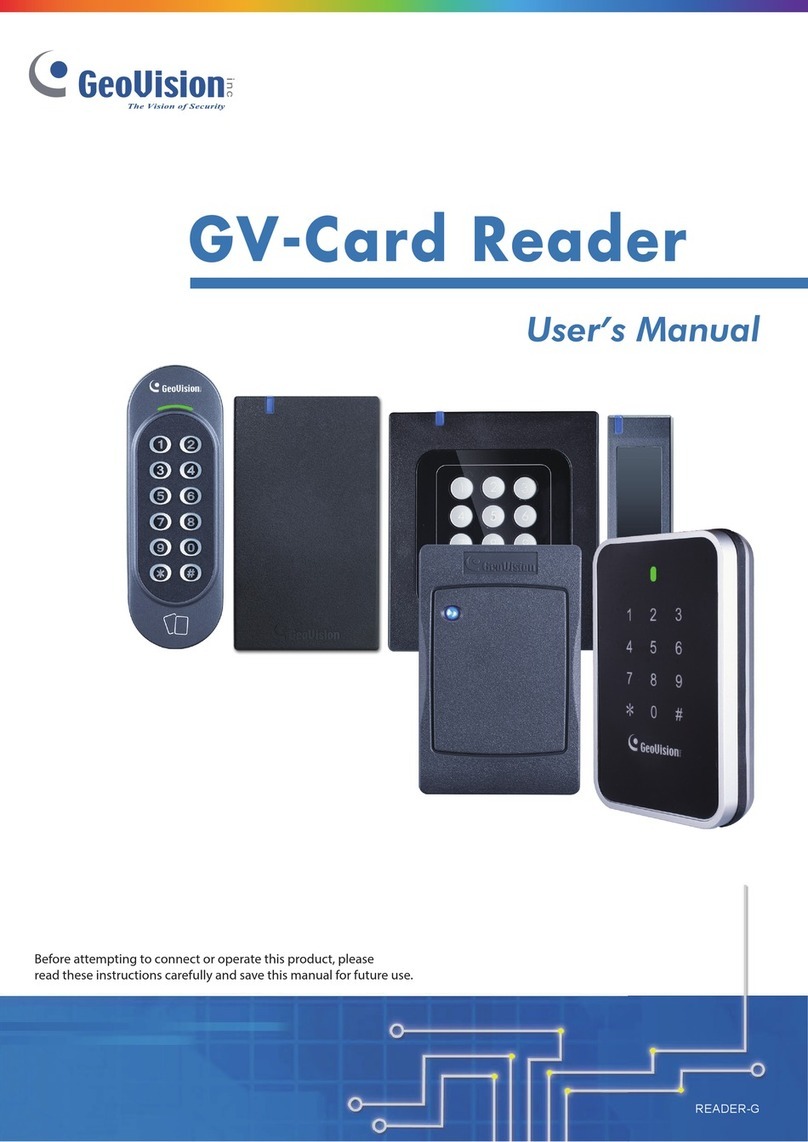
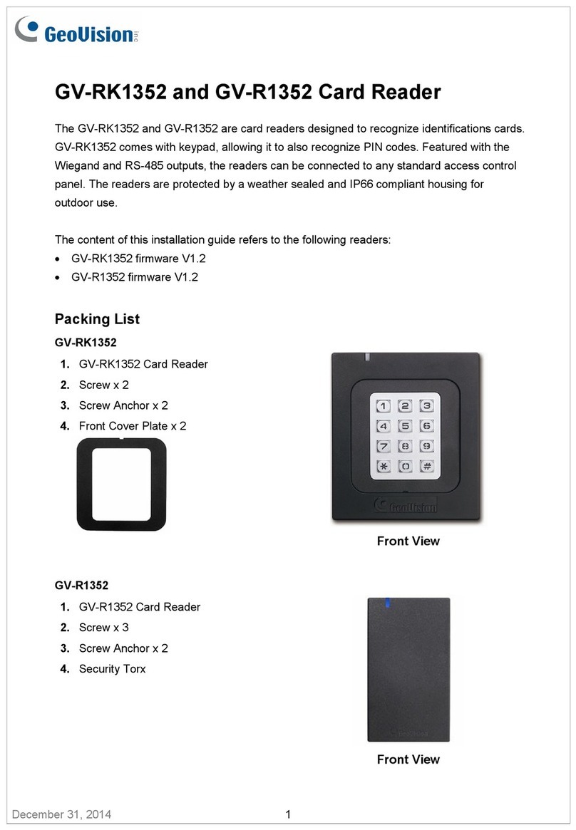
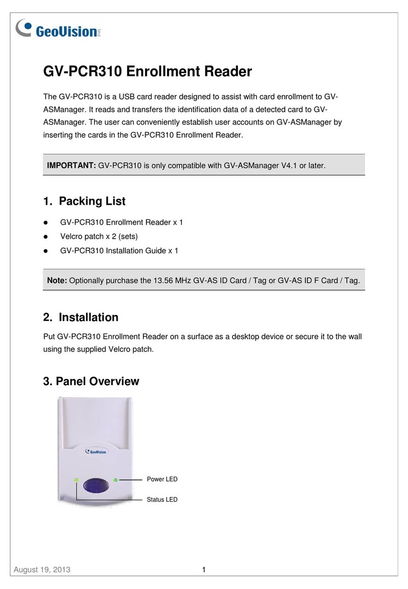
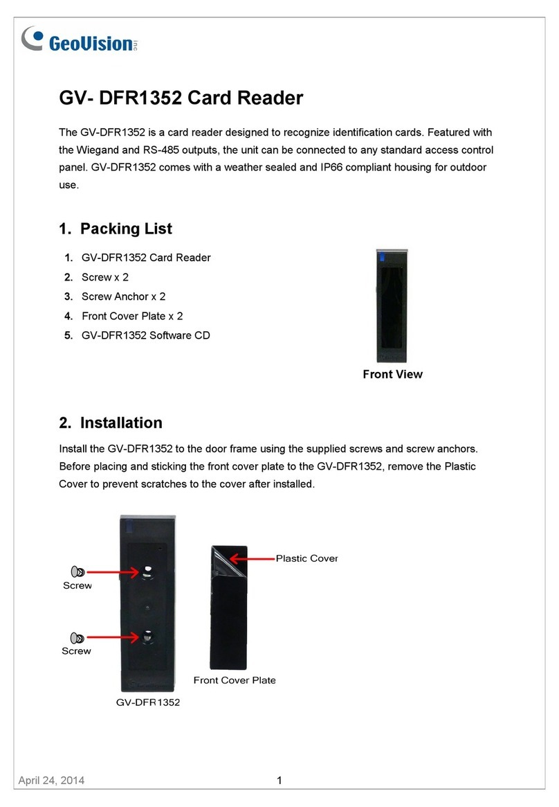
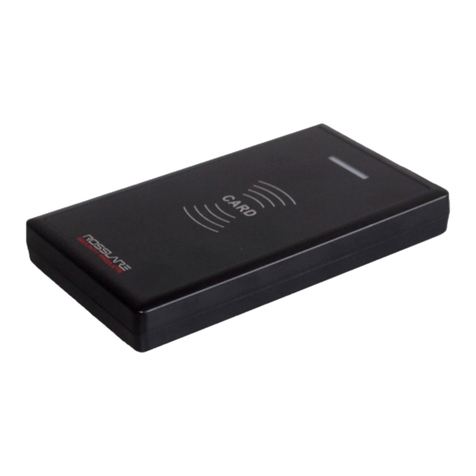
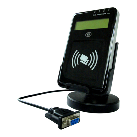
GV-Reader
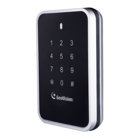
The GV-Reader includes transmit-receive antenna and electronics. It has both
Wiegand and RS-485 outputs that can be connected to an standard access
control panel. The GV-Reader has a bi-color LED indicator, which is
controllable b the host s stem and changes from red to green to indicate
access granted. The GV-Reader also has a host-controllable buzzer.
1
2
Packing List
GV-Reader x 1
Bag of screws x 1
Switch Setting
Default settings are all ON.
ID 0 1 2 3 4 5 6 7
SW5 OFF
SW 1 Beeper Control
The default mode for the Beeper Control is the internal control. When the setting
is “On”, the Reader is sounded after a card is read. When the setting is “Off”, the
Beeper is controlled externall . You can use the external beeper control line to
activate the beeper.
SW2-SW3 Green/Red L D Control
The default mode for the Green/Red LED Control is the internal control. The
LED is normall red. When a card is read, the LED flashes green. When the
setting is “Off”, the Green/Red LED is controlled externall . The external control
lines can then be used to operate the LEDs.
SW4 Master/Slave
The switch is used to select the Reader’s communication interface. When the
setting is “On”, the Reader is controlled b Wiegand signal. When the setting is
“Off”, the Reader is for RS-485 signal.
SW5-SW7 ID Setting
The switch 5 to switch 7 is used to set the Reader’s ID during a chain
connection.
SW8 RS-485 Terminal Resistor
When the setting is “On,” a 120-ohm resistor is connected between RS-485+
and RS-485-. This setting is used in the last device when multiple RS-485
devices are connected together.
NOT : After the change of dip switch settings, the unit must be reset b powering down
then up again before the new switch setting will take effect.
Overview
1234567 8
ON ECE
1234567 8
ON ECE
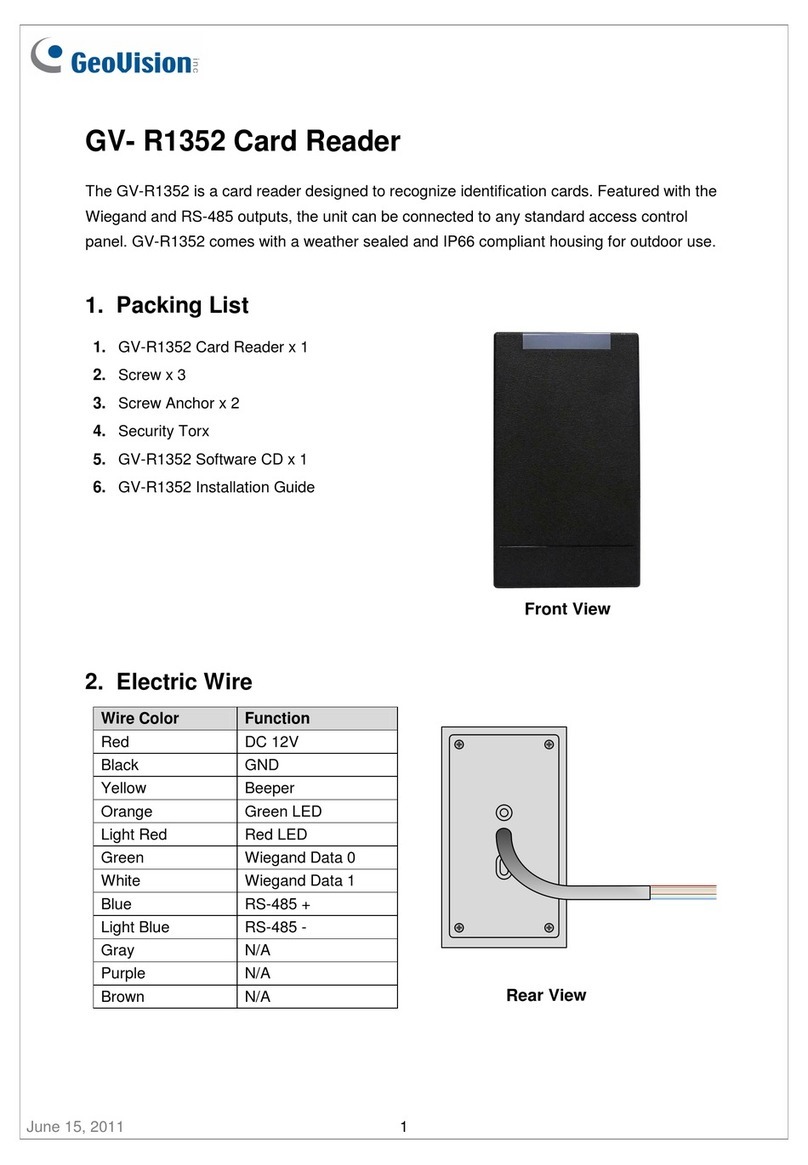
Electric Wire
Switch
Electric Wire
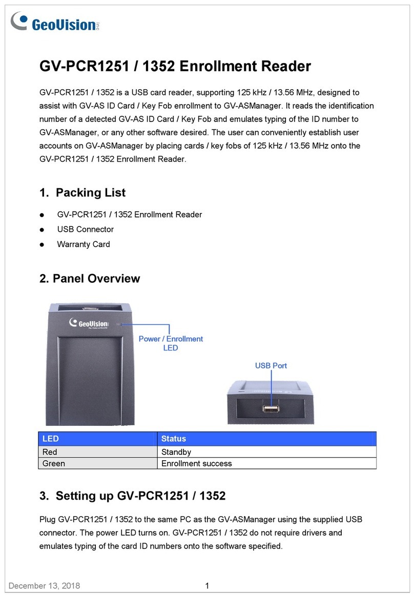
GV-Reader Software CD
GV-Reader Installation Guide
3
4
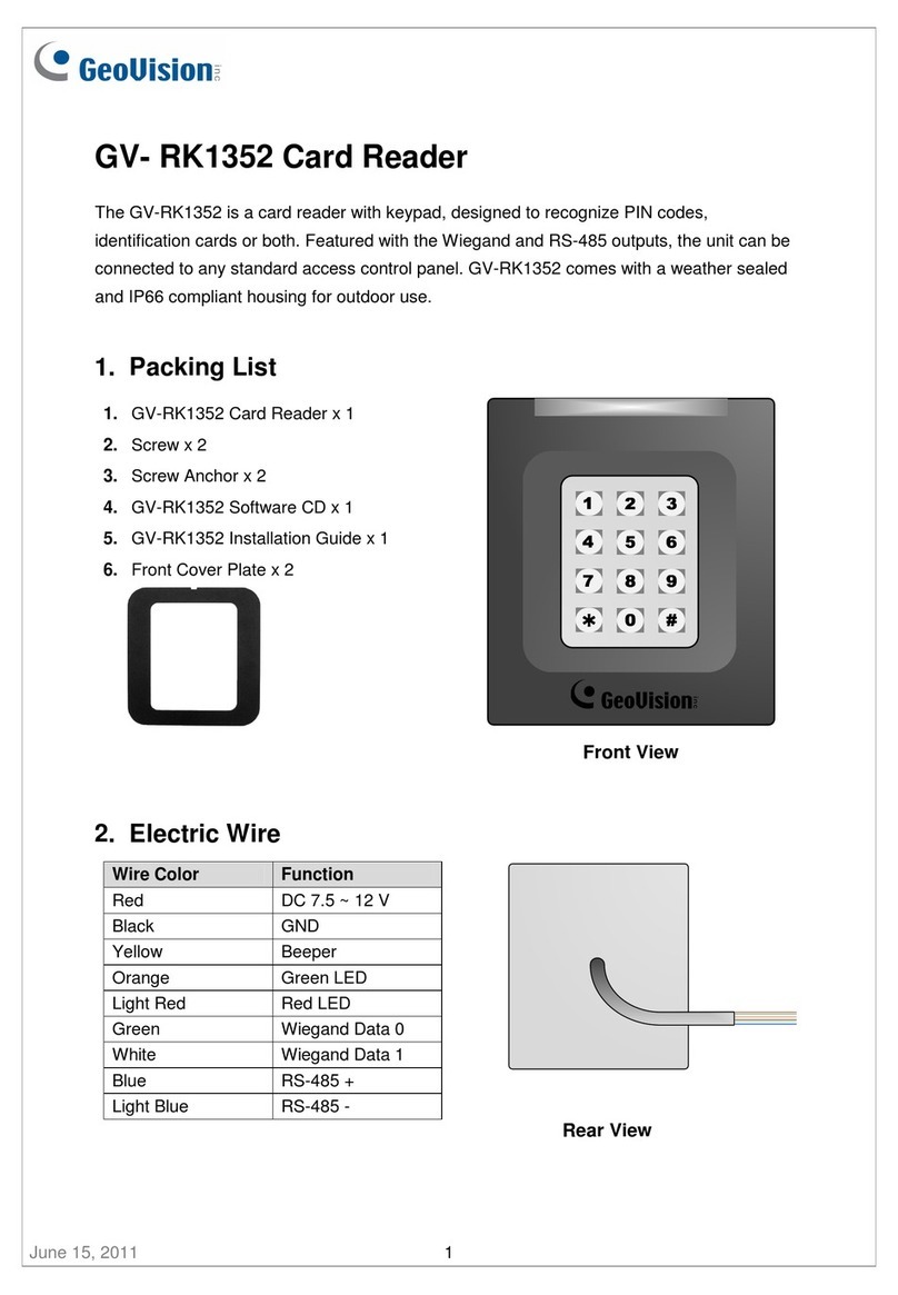
Red 7.5 ~ 12 V DC
Black GND
Green Wiegand Data0
White Wiegand Data1
Blue RS-485 +
Light Blue RS- 485 -
Yellow Beeper
Orange Green LED
Light Red Red LED
