September 23, 2010
2
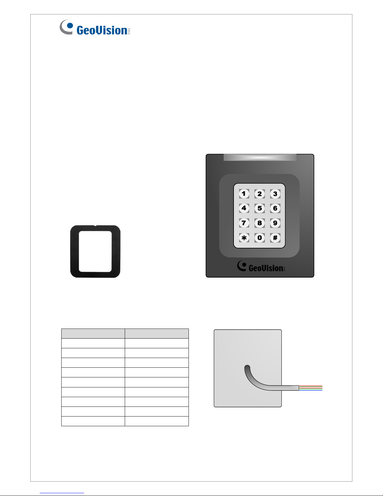
3. Keypad
When accessing an entry, you can enter the door’s PIN code on the keypad or present the
card and then enter the card’s PIN code on the keypad to be granted access. The access
mode is defined on GV-ASManager.
1. 0~9 Number Keys: Press the number keys to enter the PIN code.
2. # Key: Press the # key to confirm the PIN code.
3. ﹡Key: Press the ﹡key to cancel the PIN code.
4. LED Indicator and Beeper
In standby mode, the LED is blue. When a card is read, the LED flashes green and the
beeper beeps once.
GV-RK1352 comes with the external control wires of Green LED, Red LED and Beeper.
When these control wires are connected to GV-AS Controller, the status of LED and Beeper
can be defined by GV-AS Controller. For details on how to configure the settings, refer to
6.Configuring the Beeper and LED Indicator later in this installation guide.
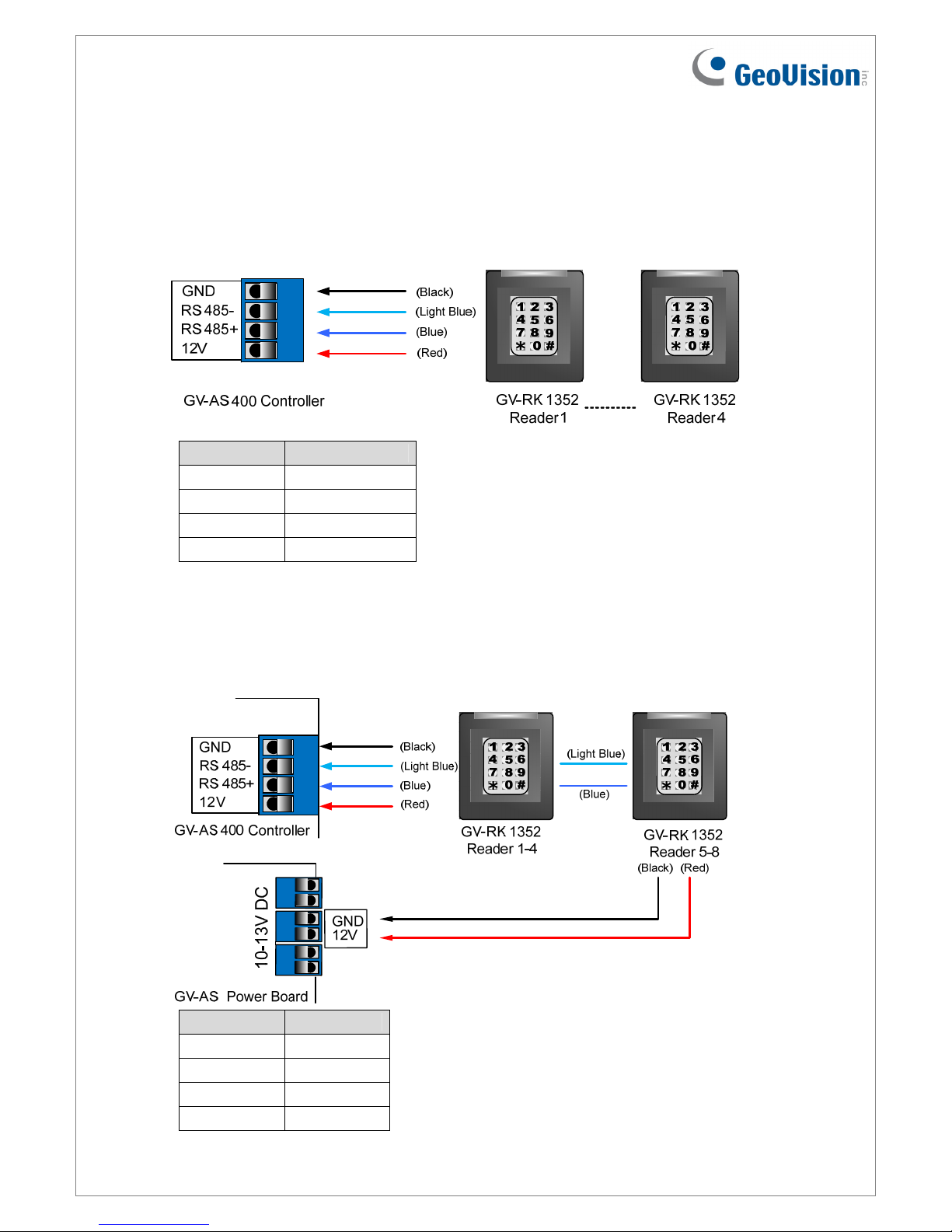
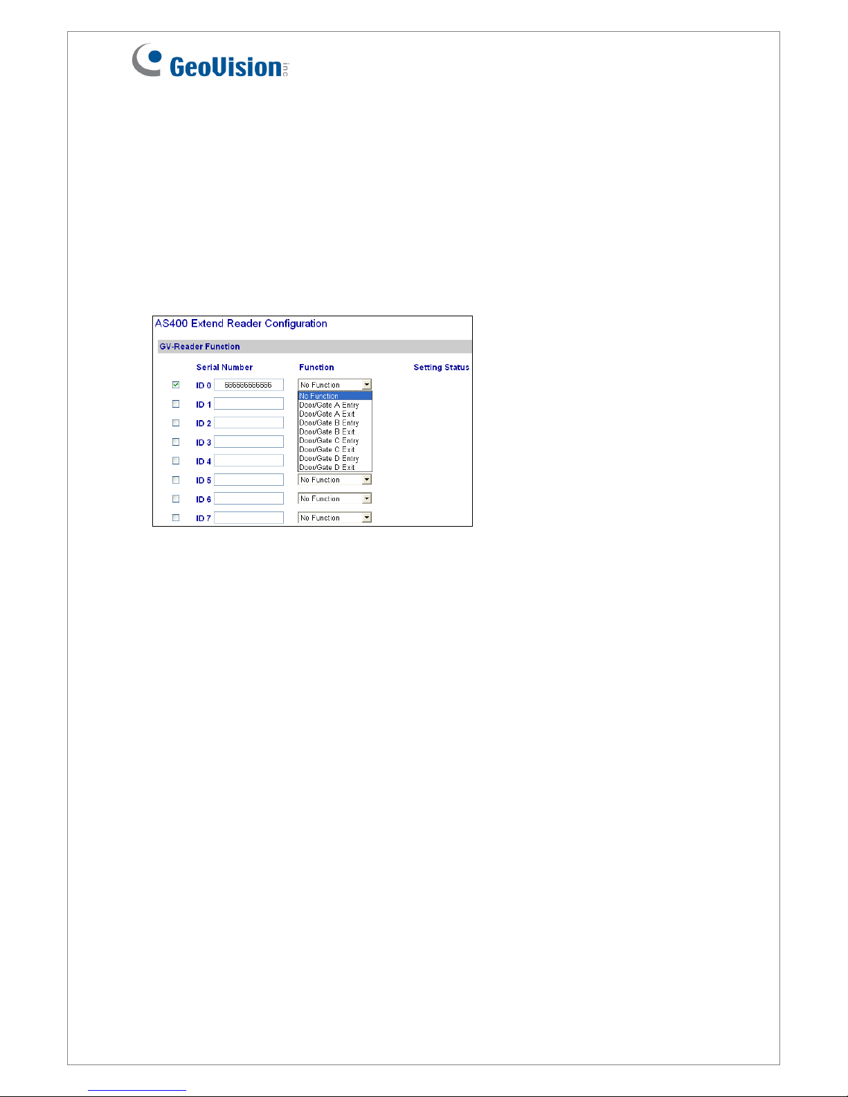
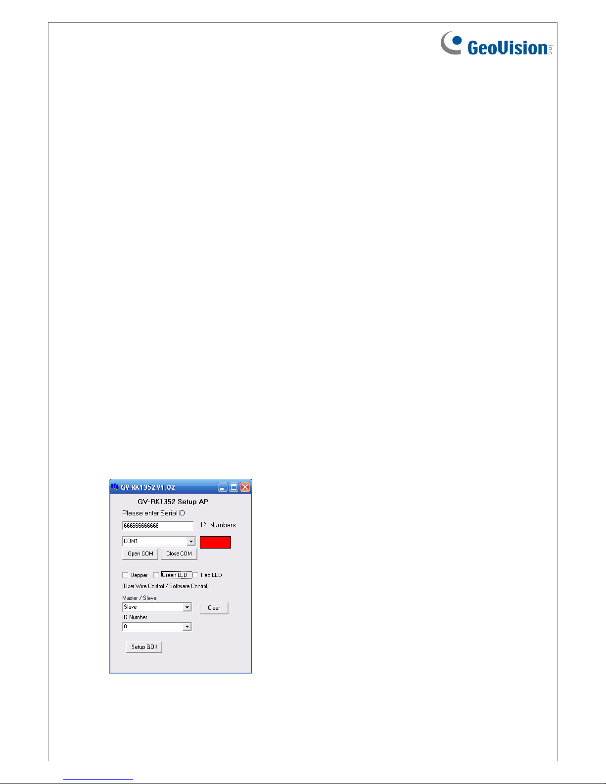
5. Connecting GV-RK1352 to GV-AS Controller
The connection between GV-RK1352 and GV-AS Controller varies with different controller
models. The following diagrams illustrate how to connect GV-RK1352 to GV-AS400
Controller through Wiegand or RS-485 interface.
Note: GV-RK1352 is compatible with GV-AS100/200/400 Controllers. However, to enable
the keypad function, you can only connect GV-RK1352 to GV-AS100/200 Controllers
through the Wiegand interface. For GV-AS400 Controller, the connection through either
Wiegand or RS-485 interface is workable for the keypad function.