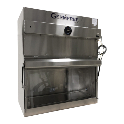
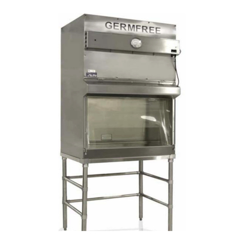
Germfree LAF User manual

Germfree - LAF Vertical Laminar Flow Hood - User Manual - v1.0 - 06/01/21 - RMH
LAF
Vertical Laminar Flow Hood
User Manual
Models LAF-6 / LAF-8

LAF Vertical Laminar Flow Hood
User Manual
ii
Germfree
4 Sunshine Blvd., Ormond Beach, Florida USA
www.germfree.com
+1 386.265.4300
For Customer Service Inquiries:
Creating Environments that Serve Life Science Innovation and Advance Global Health

LAF Vertical Laminar Flow Hood
User Manual
iii
Contents
Equipment Warranty ................................................... v
Introduction ........................................................... 1
Installation ............................................................ 2
Features............................................................... 2
Airflow ................................................................ 3
Use of the LAF Series Hood ............................................. 4
Advance Planning ................................................ 4
Good Technique ................................................. 4
Operation ....................................................... 5
Cleaning ........................................................ 5
Cautionary Notes ................................................ 6
Maintenance .......................................................... 7
Prefilters ........................................................ 7
HEPA Filters ..................................................... 7
Motor Blower .................................................... 7
Filter Diffuser .................................................... 8
Sensocon® Pressure Gauge ....................................... 8
Acrylic Sides ..................................................... 8
Lighting ......................................................... 8
Errors and Troubleshooting ....................................... 9

LAF Vertical Laminar Flow Hood
User Manual
iv
Certification / Testing Expectations ...................................... 10
Filter Housing Disassembly and Assembly ................................ 11
Parts List .............................................................. 12
Service Log ............................................................ 13
Quality Statement ..................................................... 14
Our Company ......................................................... 14
Germfree’s Mission .................................................... 14
Appendix A: LAF-6 Drawing Package
Appendix B: LAF-8 Drawing Package
Appendix C: Electrical Diagrams

LAF Vertical Laminar Flow Hood
User Manual
v
Equipment Warranty
All Germfree Laboratories equipment is constructed with quality materials to meet the highest standards of
workmanship. Our warranty covers equipment of our manufacture, which shows defects in workmanship
or materials, for a period of 24 months from date of final customer acceptance. We will send prepaid
replacements for any defective pieces. Labor incurred for repairs or defective pieces is covered until
acceptance of third party certification documents by the owner. Upon certification acceptance, labor
expenses are not covered as part of the warranty. An optional preventative maintenance contract and service
agreement is available for purchase.
THIS LIMITED GUARANTEE WILL BE HONORED ONLY IN THE LIMITS OF LOCATION/SERVICE IN WHICH
GERMFREE PLACED THE EQUIPMENT.
Germfree has the sole discretion in determining if repairs or replacement of workmanship or materials will be
provided in accordance with the warranty which is subject to all conditions or limitations included herein. The
guarantee does not cover circumstances beyond our control, or problems caused by an inability to follow the
described methods of use in the equipment manuals.
Germfree does not offer any other explicit or implicit guarantee for this product. In the case where the
exclusion of all implicit guarantees is contradicted by the law, the duration of the implicit guarantee will be
for one year from the date of purchase.
Excluded from the coverage are the routine replacement and or maintenance of consumable pieces. This
guarantee is void in the case of modification done without direct authorization by Germfree, negligence or
abuse on the part of the user.
Germfree offers optional “Total Customer Care” (TCC) plans for our equipment. The TCC programs provide
extended service and maintenance periods, by Germfree Factory Authorized Representatives (FAR), to ensure
that the product(s) provided continue to meet or exceed expected levels of performance beyond the initial
warranty period. Please contact a Germfree Salesperson for details.

LAF Vertical Laminar Flow Hood
User Manual
1
Introduction
The LAF Series Hood is designed for the unencumbered and fluid handling of non-hazardous materials in a
sterile working environment. The work area is bathed by constant positive pressure vertical airflow that has
passed through a High Efficiency Particulate Air (HEPA) filter. This filter removes organisms and particulates 0.3
micron in size with an efficiency of 99.99%. It is even more efficient for both larger and smaller particles due
to the tendency for larger particles to get inertially trapped by the filter, while smaller particles exhibit particle
diffusion in the direction of the fiber. The HEPA filter is positioned above the work area and is protected by
a removable, perforated metal diffuser located immediately below it. The airflow utilized by the LAF Series
Hood consists of moving individual streams of unidirectional, ultra-clean air along parallel lines with minimal
turbulence. This airflow paern is known as laminar.
Your LAF Series Hood is intended to be used as a work area that maximizes product quality control and
minimizes risk of product exposure to contaminates. It should only be used with non-hazardous materials since
the air being bathed over the product is reintroduced into the laboratory environment without being filtered
again. The LAF hood does not provide any protection to the user.
Your LAF Series Hood has been thoroughly tested. The HEPA filter was integrity tested by the filter manufacturer
and again at our factory during the assembly process. Refer to Certification/Testing section for more information
regarding the testing process. All testing was performed in accordance with established standards and
procedures, including ISO 14644.

LAF Vertical Laminar Flow Hood
User Manual
2
Installation
The LAF Series Hood should be transported and moved in an upright position. Your unit will arrive in two pieces
(filter housing and stand) and needs to be carefully uncrated. It is very unlikely that your hood will arrive with
damage, but if you have any concerns about the quality of the unit, contact Germfree immediately.
In order to get the hood inside the room, the filter housing needs to be removed from the unit (the hood is too
tall for standard doorways) and assembled once the unit is inside. See Appendix A: Filter Housing Disassembly
and Assembly for detailed instructions.
Once the LAF Series Hood is inside the laboratory, it should be positioned so that it is out of traffic paerns and
away from room air currents that could disrupt its airflow. At least a foot of free space should be le on both
sides of the unit for maintenance purposes. Air intake for the hood is located above the unit so you should take
care that no neighboring equipment or storage blocks the airflow. If there is a window in the room it should
remain closed at all times. The hood should not be placed in a location where air conditioning vents might
disturb the air flow. A simple smoke test will help determine a proper location for the unit. An optimal location
will have no turbulent airflow in front of, next to, or above the hood.
Features
Before shipping, the LAF Series Hood is wiped completely with an industrial cleaner/polisher. This reduces
fingerprints on the hood without leaving an oily residue. The polish is non-carcinogenic and non-toxic to the
touch. The polish will be removed from the surface of the hood during your first cleaning and poses no threat to
the cleaner.
All LAF Series Hoods are shipped complete and include the following accessories:
• Variable speed blower motor control
• Metal diuser in front of supply filter
• One (1) prefilter set
• One (1) clear acrylic adjustable sash
All electrical components are in the control panel located above the work area on the front of the unit. The
pressure gauge is also located here. The LED light and power switch are housed in the control panel. The motor
blower, speed control and circuit breaker are mounted in the filter housing, above the work deck.
There are two operator controls on the hood: a power switch and light switch. There is only a single operating
mode and the operator should not change any motor blower set points.
The unit’s speed control has been calculated and set at the factory. Adjustments may occasionally have to
be made during certification. The speed control seing should only be changed if air velocity falls below the
specified range, which usually takes several years. This should only be done by your certifier.
You should not adjust the speed control unless it is an emergency.
The LAF Series Hood does not require any specific accessories for safety reasons.

LAF Vertical Laminar Flow Hood
User Manual
3
Airflow
The LAF Series Hood intakes air through a
prefilter placed on the top of the hood. Five
motor blowers push air through a HEPA filter
and diffuser, causing uniform, laminar air to
bath over the entire work surface.
The blower motors are extremely efficient
throughout a wide pressure range; they will
overcome the resistance of both a clean and
moderately “loaded” HEPA filter. Loaded refers
to the number of particles trapped in the filter.
The variable motor blower speed control is set at
the factory to give a laminar airflow velocity of
80-100 linear feet per minute as measured by a
thermoanemometer or velometer.
As the HEPA filter becomes “loaded” with
particulate maer, the blower will overcome
a considerable increase in resistance without
having to be reset. Over time filter loading will
necessitate an adjustment of the speed control.
To best determine when the filters should be
changed, direct readings of airflow in feet per
minute should be taken. This is usually done
with a velometer or thermoanemometer.
These adjustments and measurements should
only be performed by a certifier.

LAF Vertical Laminar Flow Hood
User Manual
4
Use of the LAF Series Hood
The successful use of the LAF Series Hood depends upon two factors: advance planning and good technique.
Even the most sophisticated and elaborate system would be useless if proper technique were not employed.
The head of the involved department should make sure that personnel who use the unit are trained and exercise
good technique.
Advance Planning
To achieve maximum sterility from your unit, you must take into account the equipment and materials necessary
for the proposed project and outline the procedural details for your particular operation.
The best way to accomplish this is to use a checklist and/or protocol for both materials and procedures.
Materials should include equipment, apparatus, media, supplies, diluents, drugs and all other items that will
be used. The procedural checklist should include the order of events in sequence and other details that are
necessary for the successful completion of the proposed operation or experiment.
Your advance planning should include a layout for the arrangement of items in the work area. This should be
planned so that, if there are dirty items, they are segregated from clean ones. The movement of the dirty items
above clean items should be minimized. Base your layout on a logical progression for each specific operation.
In a complex situation, an ideal arrangement of equipment may not be achievable, so it may be necessary to
compromise.
Good Technique
The operator is the critical factor in the successful performance of any LAF Series Hood. It is dangerous to rely on
the unit to do all of the work. When properly maintained and operated, the LAF Series Hood will do an excellent
job of controlling airborne contamination.
Using your checklist, collect all items that will be placed inside the hood for the procedure. Clean all of these
items thoroughly before placing them into the work area. Keep the items at a comfortable distance away from
the open front of the unit. All items used during operation should be placed behind this line. Because the
airflow is downward, the movement of an item should not pass over or under another item. The items should be
brought around the sides of other items to maintain cleanliness.
Aer all of the items on the checklist have been arranged in the work area, the unit should have been in
operation for at least 10 minutes. Wait an additional 5 minutes before beginning the procedure. This will allow
sufficient time for the ultra-clean air passing over the work area to remove airborne contamination, especially
particulate maer from the newly introduced items.
Prior to beginning work inside the hood, the operator should wash their hands and arms with germicidal
soap. It is recommended that technicians working in the LAF Series Hood wear PPE as per regulations. This will
minimize the shedding of skin flora into the work area. Conventional laboratory coats with open cuffs allow
the entrapment of contaminated air between the technician’s wrist and forearms and the inside sleeves. This
contaminated air can thus be introduced into the work area.
Abrupt movements of forearms and hands should be avoided. Excessive activity in the room also creates
disruptive air currents. Therefore, such activity should be held to a minimum or eliminated when work is being
performed.
While working in the hood, the operator should use slow and purposeful movements, and movements should be
limited in number. Fast and erratic movements in the hood can have adverse effects on the airflow.
Since the hood does not provide any protection to the user from the activities performed, it is equally important

LAF Vertical Laminar Flow Hood
User Manual
5
for the operator to wear PPE to protect themselves as much as the product.
Operation
1. To start-up the hood, the power cord first needs to be plugged into a dedicated 10A, 235V power source.
2. The power buon can now be pushed on, which is located on the control panel. The power buon will
illuminate green while running, and the running motor blower will be audible.
3. The Sensocon® pressure gauge mounted on the front of the control panel will begin showing readings. No
work should be done in the hood until the pressure reading stabilizes in the acceptable range.
4. The light buon needs to be pushed on before work can be done in the hood. The light buon will illuminate
blue while “on”.
5. Clean the interior surfaces of the work area. Detailed cleaning instructions can be found in the next section.
6. If the hood has been on and the air has been flowing for at least 15 minutes, work can commence in the clean
hood.
Cleaning
First and most importantly, you should use and follow your facility’s Standard Operating Procedure for primary
cleaning instructions. Our cleaning instructions should be supplemental and do not take preference.
Do not use steel wool or steel pads while cleaning stainless steel or acrylic. We highly recommend not using
bleach as it can ruin the finish on the stainless steel if not done properly. Periodic cleaning of the plastic surfaces
with an acrylic cleaner, available at all home supply or hardware stores, will minimize particle accumulation on
these surfaces.
The transparent acrylic sides of the work area are designed to provide optimal light in the work area. Many
chemicals have an adverse effect on acrylic plastics. Never use household glass cleaners. Never use griy soaps
or household cleansers such as Comet® or Ajax®. Acrylics are aacked by concentrated alcohols, strong solvents,
chlorinated hydrocarbons and many aromatic hydrocarbons. They are also adversely affected by ultraviolet light.
Acrylic is unaffected by most inorganic solvents, mineral and animal oils, low concentrations of alcohols,
paraffinic and olefinic hydrocarbons, amines, alkyl monohalides, esters containing more than ten carbon
atoms, alkalines, non-oxidizing acids, salt water, photographic solutions and chemicals, petroleum oils and
greases, household cleaning products and chemicals used in treating water. For cleaning: 50% Ethyl Alcohol,
70% Isopropyl Alcohol, or a 5% bleach solution can be used. Do not use 95% or 70% Ethyl Alcohol, 99% Methyl
Alcohol or Windex®.
To clean the outside of the hood, we recommend using low linting wipes saturated with a sporicidal disinfectant,
such as PeridoxRTU®, using unidirectional, overlapping strokes. Ensure that the prefilter located above the unit
does not become saturated with cleaner. We recommend not using any abrasive cleaners such as Comet or Ajax
as they can scratch the stainless steel and acrylic windows.
Since this LAF unit should only be used to work with non-hazardous materials, a “decontamination” procedure
does not need to be completed before cleaning the inside of the hood. A “disinfectant” procedure should be
completed to ensure the hood is sanitized before more compounding occurs. The hood should be on during the
cleaning procedure, which means the blower and pressure gauge will be operational. The alarm may need to
be silenced during cleaning, which can be done by pushing the red Alarm Silence buon located on the control
panel.
Germfree recommends using a cleaning pad saturated with sporicidal disinfectant, such as PeridoxRTU®, to
clean the inside of the hood with unidirectional, overlapping strokes. The inside of the hood should be mopped
twice, and the surface should be le wet aer the second pass for at least 3 minutes. Any equipment that stays in
the hood should be cleaned with low linting wipes saturated with a sporicidal disinfectant.

LAF Vertical Laminar Flow Hood
User Manual
6
Any spills that occur inside the hood should be cleaned immediately and the work surface should be disinfected
before any more work occurs in the hood. Your facility should have a wrien plan available in case of a spill. Any
wipes or mop pads used to clean the hood should be disposed in the same way as all other waste from the hood.
Cautionary Notes
• Ensure the air intake area above the hood is never blocked with boxes, equipment, etc. Movement of air into the
hood must not be impeded.
• The air flow should not be “turned up” under the impression that faster air flow will improve the unit’s performance.
The laminar air flow is set to 80-100 linear feet per minute which has been determined to be the optimal velocity. It is
fast enough to keep contaminants o of your product, but not fast enough to break up the laminar flow into turbulent
patterns.
• Do not block the air from escaping the hood. It can create turbulent patterns in front of your product.
• Keep minimal material in the work area.
• All work in the hood should be done entirely under the hood. Laminar flow with optimal air velocity is not guaranteed
beyond the edge of the hood.
• Any spill in the hood should be cleaned immediately. Do not perform any work with a spill in the hood.
• Contaminated or non-sterile items should not be moved above sterile items. Move them in front of, behind or below
the sterile items.
• Don’t work with open cus or other loose garments that might trap air coming from the hood.

LAF Vertical Laminar Flow Hood
User Manual
7
Maintenance
Prefilters
The prefilter is located horizontally on the top of the unit and should be kept in place at all times. The prefilter
supplied with the unit is a fiberglass type similar
to an air-conditioning filter. Once the unit has
been placed into service, the prefilter should be
inspected monthly. Aer it has been determined
how long it takes for the prefilter to “load”, it
should be routinely inspected at this interval
to determine if it should be replaced. Aer
some experience is gained, you may prefer to
select an arbitrary time to replace the prefilter.
However, the prefilter should be changed at least
once every 90 days. Replacement prefilters are
available from Germfree and are usually a stock
item. Call Germfree Customer Service to order.
HEPA Filters
The average life of a HEPA filter is 3 to 5 years or longer, depending on the cleanliness of the ambient air. A
loaded HEPA filter cannot be cleaned or recycled. New filters are available from the factory and we recommend
that they be changed by qualified personnel. The filters are accessed from the top front of the unit.
Your certifier, using R.T.V. silicone sealant, can repair small holes or tears in the filter medium. The filter must be
retested for leaks aer any repair is made.
Motor Blower
The motor blowers were selected because they have the following characteristics: low noise level, low vibration
level, compatibility with the variable speed control, and most importantly, the efficiency in delivering air through
clean HEPA filters as well as those loaded with a moderate amount of particulate maer.
The motor is located above the center of the blowers. Before servicing the motors, the power cord must be
disconnected or, if this is difficult to reach, the fuses should be removed.
It should rarely be necessary to work on the motor blower assembly.

LAF Vertical Laminar Flow Hood
User Manual
8
Filter Diuser
The HEPA filter is located behind the removable, perforated metal
diffuser. Do not push items such as needles through the diffuser
holes and do not hang items from any part of the diffuser. The diffuser
should only be removed by your certifier and at that time it can be
cleaned.
During routine cleaning, do not spray the diffuser with an aerosol or
pump dispenser as it may saturate the filter. If an occasional spray
mist reaches the filter it should dry and not cause a problem.
Sensocon® Pressure Gauge
There is a Sensocon® pressure gauge mounted on the front of the control
panel. It is equipped with a digital pressure readout, set point and
alarm indicators, and a process arch. There are four directional buons,
a “cancel” buon and an “accept” buon on the gauge for menu
navigation. If the air pressure drops below the lower set point or rises
above the upper set point, a visual and audible alarm will be triggered.
The alarm can be reset by compressing the le and right arrows
simultaneously until the alarm is silenced. If the air pressure does not
return to acceptable levels, the alarm will continue to sound.
Acrylic Sides
Please refer to “Cleaning” section of the manual for maintenance reccomendations.
Lighting
There are four LED strips located under the control panel. These bulbs have several thousand hours of life
and should not need to be replaced. However, if the bulbs do need to be replaced, this can be done by liing
the control panel and removing the nuts holding the strips in place. Make sure the power switch is off before
replacing the strips. Two nuts need to be unscrewed to remove each strip. The strip can now be pulled out until it
drops out of place. Carefully remove the strip from the housing. Since LEDs contain trace amounts of gases that
can harm an individual, replaced strips should be disposed of with hazardous waste. If the strip breaks, carefully
clean the broken pieces as they can be sharp.

LAF Vertical Laminar Flow Hood
User Manual
9
Errors and Troubleshooting
The LAF Series Hood is a user-friendly machine. Pressure error messages are both visual and audible. Visual
alarms are clear and concise, and they will remain on until the issue is resolved. When an alarm is activated, verify
the error by reseing the alarm (hold le and right arrows on the Sensocon® pressure gauge simultaneously
until the alarm resets). If the alarm persists, use the table below to fix the issue.
Trouble Possible Causes Remedy
Air Supply Inoperative Main switch is off Check main switch
Verify plug is in outlet
Blue light switch should be on
No Air Circulation Blower off Check motor blower control
Blown circuit breaker Check circuit breaker on speed
control.
Break in electrical wiring Use wiring diagram and check
wiring connections
Excessive Blower Vibration Foreign maer in blower squirrel
cage
Remove foreign maer
Exhaust Air Imbalance Improper adjustment of blower
motor control
Adjust to proper reading on
pressure gauge – contact certifier
Obstruction of plenum Remove obstruction
Leak between blower and plenum Repair leak – contact certifier
Filter loaded Replace filter – contact certifier
Low Velocity Air Low voltage on house current Measure voltage – contact certifier
Filter loaded Replace filter – contact certifier
Improper adjustment of blower
motor
Adjust to proper reading on
pressure gauge – contact certifier
Obstruction in plenum Remove obstruction
Leak between blower and plenum Repair leak – contact certifier
High Velocity Air Filter rupture Repair or replace filter – contact
certifier
Supply filter gasket leak Find and repair leak – contact
certifier
Exhaust air outlet obstruction Remove obstruction
Improper adjustment of blower
motor speed control
Adjust to proper reading on
pressure gauge – contact certifier
Non-laminar Airflow Large object obstructing airflow Remove item
Large leak in filter Replace filter – contact certifier

LAF Vertical Laminar Flow Hood
User Manual
10
Certification / Testing Expectations
Your unit will need to be certified by an independent testing organization when the unit is installed and at least
once annually for the duration of the hood’s operation. When your unit is first installed, a smoke test should be
performed.
The certifier can use a smoke tube in the operating room to find the optimal placement locations for the hood.
Any turbulent air pockets or inconsistent airflow paerns can be detected by this test. The hood should be
placed in a location with a constant rate and paern of smoke dissipation. This test will not be performed aer
the initial certification unless the airflow in the building has changed or you plan on moving the machine.
During the initial certification, and every year aer, two other tests will be performed. The first will be a filter
integrity test: the certifier will pump a non-volatile solvent (such as dioctyl phthalate (DOP), polyalphaolefin
(PAO) or equivalent) over time into the assembled unit on the upstream side of the HEPA filter. An aerosol
photometer will be used to scan the downstream side for any aerosol droplets that might pass through or
around the HEPA filter. The second examination is an airflow test. Using a thermoanemometer or velometer, the
certifier will verify that the airflow in the hood is uniform and unidirectional. A thermoanemometer uses a heated
probe set in an airstream to determine air speed. The probe determines the heating power required to maintain
the high probe temperature. This power is proportional to air speed. Alternatively, the velometer uses a probe
that intakes air, and the force against the meter causes a deflection in the needle.
If your facility does not have a certifier, Germfree can assist in finding one in your area.

LAF Vertical Laminar Flow Hood
User Manual
11
Filter Housing Disassembly and Assembly
Your hood is transported in two pieces and operational. Once the filter housing is placed on the frame, it can be
plugged into an outlet and will be ready to be certified. Placing the filter housing on the stand requires at least
four people to ensure the hood is not damaged during the process.
The filter housing needs to be lied by the li bars located on the le and right sides of the housing. It will be
have to be lied completely over the stand and lowered into place on the gasket. There is a rim that goes around
the stand that fits the filter housing exactly so it won’t shi. The filter housing sits on a gasket, which will create
the seal necessary for the hood to operate. The HEPA filter is exposed on the boom of the housing so use slow,
careful and deliberate movements so the filter is not accidentally damaged.
The control panel is connected to the filter housing by a few pins, a camlock for power supply, and a clear plastic
tube for pressure connection to the Sensocon pressure gauge. These are aached before shipping so you should
not have to connect them.
To remove the filter housing from the stand, complete the steps explained above in reverse order. Four
individuals will need to li the filter housing from the stand by the li bars on the right and le side of the
housing. If you are placing the filter housing on the ground, rotate the unit so it sits on the back side of the
housing. The HEPA filter is exposed on the underside of the housing so refrain from placing that side directly on
the ground.
Fig. 1 - Camlock for Power Supply
Fig. 2 - Port for Pressure Tube

LAF Vertical Laminar Flow Hood
User Manual
12
Parts List
Any consumable materials listed below can be replaced by contacting Germfree at +1 386.265.4300 or
FILTERS • HEPA (High Eciency Particulate Air)
• HEPA Air Filter – 73” x 29” x 3”
• Germfree Part Number – 375-1068-00
• Prefilters
• LAF Prefilter – Qty. 3 @ 25 ½ x 29 ¾ x 1
• Germfree Part Number – 375-2062-00
MOTOR/BLOWER • Qty. 5 – Fan Blower Variable Speed 9.8” diameter, 230V, 60Hz
• Rosenberg Motors Part Number – Z27-03
• Germfree Part Number – 183-0072-00
PRESSURE GAUGE • Sensocon Pressure Gauge, 0-2”, with low flow alarm
• Sensocon Part Number – A4-1000-03
• Germfree Part Number – 002-1200-00
VELOCITY PROBE • Degree Controls Velocity Sensor, 0-200 CFM, 11.2”
• Degree Controls Part Number – Fs26701
• Germfree Part Number – 157-2023-03
POWER BUTTON • Push Button, Green Illuminated 24V LED
• EAO Part Number: 82-6153.2134
• Germfree Part Number: 170-0107-00
LIGHT BUTTON • Push Button, Blue Illuminated 24V LED
• EAO Part Number: 82-6151.2124
• Germfree Part Number: 170-0108-00
ALARM SILENCE BUTTON • Push Button, Red Illuminated 24V LED
• RS Pro Part Number – 8118553
• Germfree Part Number – 170-0104-00
CIRCUIT BREAKER • 10 Amp, 1 pole, Push to Reset
• Potter & Brumfield Part Number: W58-XB-1A4A-10
• Germfree Part Number: 163-0062-00
SWITCH • Push Button, Blue Illuminated 24V LED
• EAO Part Number: 82-6151.2124
• Germfree Part Number: 170-0108-00
CIRCUIT BREAKER • 20 Amp, 1 pole, Push to Reset
• Potter & Brumfield Part Number: W58-XB-1A4A-5
• Germfree Part Number: 163-0050-00
SPEED CONTROL • Qty. 2 – 24V, 20A. Motor Speed Control with Mounting Plate
• Evolution Controls Inc. Part Number – EVO/ECM-VCU-MP
• Germfree Part Number – 332-0043-00
LIGHTING • Qty. 2 – LED, 4’, T5, 3400 Lumens, 25W Light Fixture
• V-TAC USA Part Number: VT-T5DW25/840/4
• Germfree Part Number: 147-1069-00
POWER CORD • Twist-Lock, 20A, 125V, 2 Pole, 3 Wire
• Hubbell Part Number: HBL2311
• Germfree Part Number: 583-0018-01

LAF Vertical Laminar Flow Hood
User Manual
13
Service Log
Date Service Provided

LAF Vertical Laminar Flow Hood
User Manual
14
Our Company
Germfree has been a leading innovator in aseptic
control and isolation systems since 1962.
We design and manufacture a diverse range
of equipment and facilities for life science
applications.
Our systems are integral to critical processes across
many sectors. We specialize in complex projects and
custom applications that serve the rigorous demands
of our clients. Our high-specification bioGO
Modular Facilities operate across the world, and are
sustainable as permanent facilities in remote regions
with harsh conditions.
Quality Statement
Accountability
We will deliver our products on time, as promised, and
free from defects.
Ownership
We will strive to exceed expectations at every level
and we will work to make sure that each customer is
satisfied with the service that they receive.
Longevity
All of our products are constructed from the highest
quality materials and are designed to operate reliably
for decades. We stand behind our work and take
pride in our superior crasmanship.
Germfree’s Mission
Creating Environments that Serve Life Science Innovation and Advance Global Health
Germfree
4 Sunshine Blvd.
Ormond Beach, Florida, USA 32174
+1 386.265.4300
www.germfree.com

LAF Vertical Laminar Flow Hood
User Manual
15
Appendix A:
LAF-6 Drawing Package
This manual suits for next models
2
Table of contents
Other Germfree Laboratory Equipment manuals
Popular Laboratory Equipment manuals by other brands

Drucker Diagnostics
Drucker Diagnostics Owl Manor HORIZON 24 Flex Operator's manual

Rocker
Rocker 197000-36 instruction manual

Okolab
Okolab H301-ALPHA3-LARGE user manual

WEPA
WEPA TopiTec Automatic user manual

Thermo Scientific
Thermo Scientific 88870007 operating manual

Sartorius
Sartorius WZA N Series installation instructions