IKA ULTRA-TURRAX Tube Drive P control User manual

16
Contents
EN
Declaration of conformity
Explanation of symbols
General hazard
This symbol identifies information that is of vital
importance for safeguarding your health
and safety. Disregarding this information can
lead to health impairment and injuries.
This symbol identifies information that is of
importance for the technically correct
functioning of the system. Disregarding this
information can result in damage to the device
or to system components.
Risk of hand injury.
WARNING
DANGER
DANGER
Seite
1 Declaration of conformity 16
2 Explication of warning symbols 16
3 Safety instructions 17
4 Unpacking 18
5 Correct use 18
6 Useful facts 19
7 Interfaces and outputs 19
8 Commissioning 20
9 Switching on 20
10 Factory setting 21
10.1 Resetting parameters to factory setting (RESET) 21
11 Set menu parameters 22
11.1 Operation mode 22
11.2 Operation language 22
11.3 Maximum rotation speed (max rpm) 23
11.4 Maximum timer value (timer max) 23
12 Set working parameters 24
12.1 Target speed (target rpm) 24
12.2 Timer value (timer sec) 24
12.3 Reverse function (rev sec) 24
12.4 Turbo function 24
13 Error codes 25
14 Maintenance 25
15 Accessories 26
16 Warranty 26
17 Technical data 27
Source language: German
We declare under our sole responsibility that this product corro-
sponds to the regulations 2014/35/EU, 2006/42/EC, 2014/30/EU
and 2011/65/EU and conforms with the standards or standardized
documents EN 61010-1, EN 61010-2-051, EN 61326-1, EN 60529
and EN ISO 12100.
A copy of the complete EU Declaration of Conformity can be re-
1
2

17
For your protection
• Read the operating instructions in full before starting up
and follow the safety instructions.
• Follow the safety instructions, guidelines, occupational health
and safety and accident prevention regulations.
• Keep the operating instructions in a place where they can be
accessed by everyone.
• Ensure that only trained staff work with the appliance.
•
The device must be supervised at all times when in operation.
•
Caution! For research purposes only! Not suitable for di-
agnostic use (in accordance with the IVD Directive).
The
device
must only be operated with a tube
attached; with no tube there is a risk of injury
from the rotating locating pin.
• Hearing protection must be worn when working with BMT-20
or BMT-50 tubes.
Wear your personal protective equipment in
accordance with the hazard category of the
medium to be processed. There is a risk of:
- splashing liquids
- projectile parts
- body parts, hair, clothing and jewellery getting caught.
• Set up the
device
in a spacious area on an even, stable, clean,
non-slip, dry and fireproof surface.
• The feet of the
device
must be clean and undamaged.
• The
device
is not suitable for manual operation.
• The
device
may heat up when in use.
•
Check the device and accessories beforehand for damage each
time when you use them. Do not use damaged components.
• Ensure that the cover on the tube is screwed on tightly.
• Ensure that the tube is firmly attached to the bayonet lock con-
nector on the drive unit prior to operating the device.
• The tube must only be attached and removed while the motor
is stationary.
The IKA tubes must always be closed when the
device is in operation. Switch off the device im-
mediately if any material leaks from the tube. Clean the device.
• Always open the tube carefully after use as the media in the
tube may heat up due to transfer of energy during operation,
leading to pressurization of the container: risk of material spray-
ing, protective equipment must be worn.
• The temperature of the material must not exceed 40 °C.
• Only use tubes approved by IKA.
•
Only process media that will not react dangerously to the extra
energy produced through processing. This also applies to any extra
energy produced in other ways, e.g. through light irradiation.
• Do not use the device in explosive atmospheres, it is not EX-
protected.
•
With substances capable of forming an explosive mixture, appropriate
safety measures must be applied, e.g. working under a fume hood.
•
To avoid body injury and property damage, observe the relevant
safety and accident prevention measures when processing haz-
ardous materials.
• The device doesn’t start up again automatically following a cut
in the power supply.
• Safe operation is only guaranteed with the accessories described
in the ”Accessories” chapter.
For protection of the device
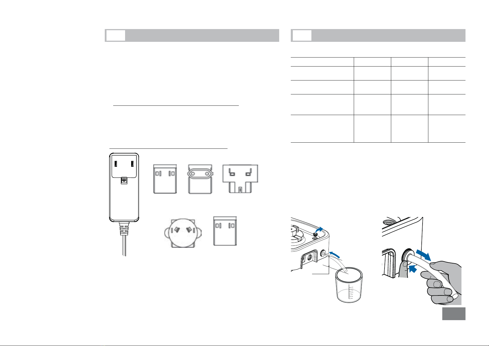
• The voltage stated on the name plate must correspond to the
mains voltage.
• The device must only be operated with the original plug-in pow-
er supply unit.
•
Protect the device and accessories from bumps and impacts.
• The device may only be opened by experts.
Safety instructions
3
DANGER
DANGER
WARNING

18
Unpacking
• Unpacking:
- Please unpack the device carefully
- In the case of any damage a fact report must be set immedi-
ately (for post, rail or forwarder)
• Delivery scope:
- Tube Drive P control
- Power supply unit with exchangeable adapters
- Removal hook
- Plastic hose
- Operating instructions
- A warranty card.
Power supply unit with exchangeable adapters
4
Additional in the suite-case variant:
1 x ST-20 1 x DT-20
1 x BMT-20-S 1 x BMT-20-G
Correct use5
• Use:
Application Volume Mode
with Tube ST-20...
with Tube ST-50...
Mixing
Stirring
2 - 15 ml
15 - 50 ml
A, B, P1-P9,
Turbo, Rev
with Tube DT-20...
with Tube DT-50...
Dispersing
Stirring
5 - 15 ml
15 - 50 ml
A, B, P1-P9,
Turbo, Rev
with Tube BMT-20...
with Tube BMT-50...
Crushing
Mixing
wet/dry
2 - 15 ml
15 - 50 ml
A, B, P1-P9,
Turbo, Rev
with Tube DIS 50...
with Tube DIS 300... X
Crushing
Mixing
Dissolving
wet
15 - 50 ml
100 - 300 ml
A, B, P1-P9,
Turbo
(for DIS 50 only)
Rev
~
US
(N)
Australia
(A)
China
(C)
UK
(B)
Europe
(E)
XNote: When the DIS 300-S-M tube is used, please remove the
drain opening plug and connect the included plastic hose to the drain
opening before operation!
Thus, the liquid can be drained out to a suitable vessel (more than
300 ml) in case of leakage of the DIS-300 S-M.
The vessel must be underneath the device and the hose mustn’t
bend upwards).
For removing the plastic hose, press the flange of the drain open-
ing, meanwhile, pull the plastic hose out.
100
200
300
> 20 mm

19
Useful facts
Changes in viscosity and volume caused by processing of disper-
sion media may cause small fluctuations in the speed of the device.
6
Interfaces and outputs
Remote control:
The device can be operated in “Remote” mode via USB interface us-
ing labworldsoft
®
laboratory software. The USB interface is located
on the back side on the device and can be connected to a PC using
the USB cable.
Note: Please note the system requirements as well as the operating
instructions and help section included within the software.
USB Interface:
The Universal Serial Bus (USB) is a serial bus for connecting the
device to the PC. Equipped with USB devices can be connected to
a PC during operation (hot plugging). Connected devices and their
properties are automatically recognized. Use the USB interface in
conjunction with labworldsoft
®
for operation in "Remote" mode
and also to update the firmware.
7
Installation:
First, download the latest driver for IKA devices with USB interface
from: http://www.ika.com/ika/lws/download/usb-driver.zip.
Install the driver by running the setup file. Then connect the
IKA
device through the USB data cable to the PC. The data
communication is via a virtual COM port. Configuration, command
syntax and commands of the virtual COM ports are as described
in RS 232 interface.
Command syntax and format:
The following applies to the command set:
- Commands are generally sent from the computer (Master) to
the device (Slave).
- The device sends only at the computer’s request. Even fault in-
dications cannot be sent spontaneously from the device to the
computer (automation system).
- Commands are transmitted in capital letters.
- Commands and parameters including successive parameters are
separated by at least one space (Code: hex 0x20).
- Each individual command (incl. parameters and data) and each
response are terminated with Blank CR LF (Code: hex 0x20 hex
0x0d hex 0x20 hex 0x0A) and have a maximum length of 80
characters.
- The decimal separator in a number is a dot (Code: hex 0x2E).
The above details correspond as far as possible to the recommen-
dations of the NAMUR working party (NAMUR recommendations
for the design of electrical plug connections for analogue and
digital signal transmission on individual items of laboratory control
equipment, rev. 2.9).
• Range of use (indoor use only):
- Laboratories - Schools
- Pharmacies - Universities
The device is suitable for use in residential areas and all other areas.
The safety of the user cannot be guaranteed:
- If the device is operated with accessories that are not supplied or
recommended by the manufacturer
- If the device is operated improperly contrary to the manufacture’s
specifications
- If the device is operated improperly contrary to the manufacturer’s
specifications.

20
The NAMUR commands and the additional specific IKA commands
commissioning serve only as low level commands for communica-
tion between the tube driver and the PC. With a suitable terminal
or communications program these commands can be transmitted
directly to the tube driver. The IKA software package, labworldsoft,
provides a convenient tool for controlling tube driver and collecting
data under MS Windows, and includes graphical entry features, for
motor speed ramps for example.
The following table summarize the (NAMUR) commands under-
stood by the tube drive control up to Version 2.9.
Abbreviation used:
m = Numbering parameter (integer)
X = 4 Speed
Commands Function Remark
IN_NAME Request designation.
Start the Remote control
function.
Device Keypad not avail-
able except “power”
button is pressed, after
this command is sent to
device. "Remote" symbol is
displayed.
RESET Switch to normal operation
Device Keypad available
again, and clear the "Re-
mote" symbol.
IN_PV_X
X=4
Read actual speed value
IN_SP_X
X=4
Read target value input
OUT_SP_X m
X=4
Set target speed value, input:
rpm
START_X
X=4
Switch on appliance remote
function.
Start value function with setting.
IN_SOFTWARE Request software ID,
number, date and version
Commissioning
Pay attention to the ambient conditions listed in the “Technical
Data”.
If these conditions are met, the unit is ready
for operating when the mains plug has been
plugged in.
Fit the tube carefully and ensure it is
properly attached.
If above procedures are not followed,
safe operation can not be guaranteed
and/or the equipment may be dam-
aged.
8
Switching on
)Press “Power” button (A) to switch on the device, see Fig. 1.
ÖThe start-up screen will be displayed for several seconds. This screen
shows the unit designation and the software version.
9

21
ÖThen, the system check screen will be displayed for several seconds.
Symbols are shown on the screen, including the working mode set-
ting, the target speed, the maximum rotation speed (rpm) and timer
maximum value etc. of the device.
Factory setting
The device is supplied with following factory setting:
Menu Settings:
mode A
max rpm 6000 rpm
timer max 30 minute
language English
Working Setting:
target rpm 400 rpm
timer sec off
rev sec off
10
Resetting parameters to factory setting
10.1
To reset the parameters to the factory settings, proceed as following:
• Pull out main plug from the device.
•
Hold the controller buttons “Menu/Back” and “Timer” simultane-
ously and re-insert main plug in power outlet.
• The unit is now reset to the factory settings.
c
g
d
e
f
h
Symbols Explanation
cMaximum rotation speed of the device (If “Turbo” function is
activated, the maximum rotation speed could reach 8000 rpm).
dRotation symbol (The symbol will change into 3or 4if “Rev”
function is activated).
eRotation speed setting.
fOperation mode.
g“Timer” maximum value of the device.
h“Timer” symbol.
ÖAfter the system check screen, the working screen will appear
and the device is ready for operation.
Note: Figure above shows specified values corresponding to the
default settings at delivery.

22
Setting menu parameters
The device can be operated in mode A, B and P1 to P9. The mode
setting will be stored automatically when operation is over, or the
device is switched off. User may change the mode setting in the
main menu if necessary.
• Operation mode A
In this mode, when current operation is over or the device is
switched off, all working settings will not be stored.
• Operation mode B
In this mode, when current operation is over or the device is
switched off, all menu and working settings will be stored.
• Operation mode P1 - P9
In mode P1-P9, the user can set and save required parameters,
(target speed, timer value and rev value) in program. The param-
eter settings can only be changed in the menu program. These
settings can also be used directly when necessary.
• Setting operation mode between A and B
)Press the “Menu/Back” button (C) in the main menu.
)Turn the “Rotating/Pressing” knob (B) to select the “mode” item
in the main menu.
)Press the “Rotating/Pressing” knob (B).
)Turn the “Rotating/Pressing” knob (B) to select mode A or B in
submenu.
)Press the “Rotating/Pressing” knob (B) again to complete the
process.
)Press the “Menu/Back” button (C) to return to the working screen.
• Setting operation mode between P1 and P9
)Press the “Menu/Back” button (C) in the main menu.
)Turn the “Rotating/Pressing” knob (B) to select the “mode”
item in the main menu.
11
Operation mode11.1
)Press the “Rotating/Pressing” knob (B).
)Turn the “Rotating/Pressing” knob (B) to select the “mode”
item in mode P1 and P9 in submenu.
)Press the “Rotating/Pressing” knob (B) and enter desired
menu program.
)
Turn the “Rotating/Pressing” knob (B) to select desired pro-
gram item.
)Press the “Rotating/Pressing” knob (B) .
)Turn the “Rotating/Pressing” knob (B) to change the value.
)Press the “Rotating/Pressing” knob (B) again to complete the
setting.
)Press the “Menu/back” button (C) to complete the process,
display will return to working screen.
Note: The target speed and timer value in the program should be
less than “rpm max” and “timer max” setting in menu. Otherwise,
the device will run according to the setting in the menu.
Operation language11.2
The language can be set to: English, German, Chinese, French,
Spanish, Italian and Korean. The language setting will be stored au-
tomatically when operation is over or the device is switched off.
User can change the language setting in the main menu if necessary.
• Setting operation language
)Press the “Menu/Back” button (C) in the main menu.
)
Turn the “Rotating/Pressing” knob (B) to select the “lan-
guage” item in the main menu.
)
Press the “Rotating/Pressing” knob (B) to confirm “lan-
guage”.
)
Turn the “Rotating/Pressing” knob (B) to select a language.
)Press the “Rotating/Pressing” knob (B) again to complete
the setting.
)Press the “Menu/Back” button (C) to return to the working
screen.

23
Maximum rotation speed (max rpm)
11.3 Timer maximum value (timer max)
11.4
The default “timer max” is 30 minutes in the device. User can
change the setting in 10 second intervals and up to 30 minutes
in the main menu.
The “timer max” setting will be stored automatically when opera-
tion is over or the device is switched off.
• Set “timer max”
)Press the “Menu/Back” button (C) in the main menu.
)Turn the “Rotating/Pressing” knob (B) to select the “timer max”
in the main menu.
)Press the “Rotating/Pressing” knob (B)
ÖA mark
will appear to indicate the activated item.
)Turn the “Rotating/Pressing” knob (B) to change the value.
)Press the “Rotating/Pressing” knob (B) again to complete the
process
)Press the “Menu/Back” button (C) to return to the working
screen.
Note: The timer „timer max” can be adjusted with the “Rotating/
Pressing” knob (B) in a range from 10 seconds to 30 minutes. This
is achieved in magnitudes of 10 seconds. In remote control mode
via computer, adjusting magnitude is 1 second.
The default setting “max rpm” is 6000 rpm in the device. User
can change the setting to the range of 400 to 6000 rpm in the
main menu.
The “max rpm” setting will be stored automatically when opera-
tion is over or the device is switched off.
• Setting “max rpm”
)Press the “Menu/Back” button (C) in the main menu.
)Turn the “Rotating/Pressing” knob (B) to select the “max
rpm item in the main menu.
)Press the “Rotating/Pressing” knob (B).
ÖA mark
will appear to indicate the activated item.
)Turn the “Rotating/Pressing” knob (B) to adjust the value.
)Press the “Rotating/Pressing” knob (B) again to complete
the process.
)Press the “Menu/Back” button (C) to return to the working
screen.
Note: The speed „max rpm” can be adjusted with the “Rotating/
Pressing” knob (B) in a range between 400 to 6000 rpm. This is
achieved in magnitudes of 10 rpm. In remote control mode via
computer, adjusting magnitude is 1 rpm.

24
Setting working parameters12
Set “target rpm” within “rpm max” range in the working screen
by rotating the “Rotating/Pressing” knob (B). Adjustment magni-
tude is 10 rpm. In remote control mode via computer, adjusting
magnitude is 1 rpm.
• Setting “target rpm” in working screen
)
Turn the “Rotating/Pressing” knob (B) to change the value.
)
Press “Rotating/Pressing” knob (B) to start working.
Ö
Rotation symbol ( ,3,4) indicates running.
Target speed (target rpm)
12.1
Timer function
12.2
Reverse (Rev) function12.3
Turbo Function12.4
The rotation speed can increase to 8000 rpm in several seconds by
pressing down „Turbo“ button (F) during operating. For tube protec-
tion, Turbo function can only last 60 seconds at most if you press
down „Turbo“ button (F). Several seconds later, Turbo function can
be activated again after symbol has disappeared.
• Activate and hold “Turbo” function in working screen:
)Press down „Turbo“ button (F) over 2 seconds when the de-
vice is working, to activate Turbo function.
ÖThe Turbo mark appears and changes alternately to in-
dicate that the Turbo function is activated and rotation speed
will increase to 8000 rpm in a short time.
)Release “Turbo” button (F).
When setting “Rev” value with the “Rotating/Pressing” knob (B), the
value can be set from 10 to 60 seconds where adjustment magni-
tude is 1 second.
Note: If both “Rev” function and “Timer” function are activated,
the “Rev” value should be less than “Timer” value. Otherwise, the
reverse function will not work.
If the reverse function is activated, press “Rev” button (E) dur-
ing running, the reverse function will be deactivated. Press “Rev”
button (E) again, the reverse function will be reactivated and the
screen will indicate “Rev” value setting.
•
Setting “Rev” timer (rev sec) in working screen
)Press “Rev” button (E) to activate the reverse setting in the
working screen.
)Turn the “Rotating/Pressing” knob (B) to change the value.
)Press “Rev” button (E) again to complete the setting.
ÖCurrent values are stored.
Set “Timer” within “timer max” range in the working screen by ro-
tating the “Rotating/Pressing” knob (B). Adjustment magnitude is 10
seconds. In remote control mode via computer, adjusting magnitude
is 1 second.
If the “Timer” is deactivated when the device is started, the device
will automatically count from 0 to 30 minutes and then the unit will
stop running.
• Setting “Timer” value (timer sec) in working screen
)Press “Timer” button (D) to activate the timer setting in the
working screen.
)Turn the “Rotating/Pressing” knob (B) to change the value.
)Press “Timer” button (D) again to complete the setting.
ÖCurrent values are stored.

25
Error codes13
Maintenance14
The drive unit is maintenance-free but not immune from wear. The
carbon brushes of the motor wear down over the time.
For cleaning disconnect the main plug.
Only use cleansing agents which have been recommended by IKA.
Dirt
Cleaning agent
Dyes
isopropyl alcohol
Construction materials water containing tenside/isopropyl alcohol
Cosmetics
water containing tenside/isopropyl alcohol
Foodstuffs water containing tenside
Fuels water containing tenside
For materials which are not listed, please request information from
IKA application support.
Wear protective gloves during cleaning the instruments.
Electrical instruments may not be placed in the cleansing agent for
the purpose of cleaning.
Do not allow moisture to get into the instrument when cleaning.
Before using another than the recommended method for cleaning
or decontamination, the user must ascertain with IKA that this
method does not destroy the instrument.
Spare parts order:
When ordering spare parts, please give:
-
machine type
-
manufacturing number, see type plate
- item and designation of the spare part, see www.ika.com,
spare parts diagram and spare parts list.
ÖTurbo function will be stopped and rotation speed will return
to original setting. A symbol appears to indicate that the
Turbo function is stopped. Before this symbol disappears,
turbo function can not be activated again.
Any malfunction during operation may be identified by an error
message on the display.
Proceed as follows in such cases:
)
Switch off device using the power switch
)
Carry out corrective measures
)
Restart the device.
Error
code
Cause
Effect Solution
Error 3
Inside temperature is
too high
motor off
- Switch off the device and
let it cool down.
- Restart the
device
.
Error 4
Motor can’t run normal
(can’t start or not reach
the target speed)
motor off
- Switch off the
device.
- Check the structure for
possible blockades
Error 47
Error 48
Overload
motor off
- Switch off the device
- Decrease the speed setting
or the load
Error 50
Tube is protected in
order to avoid overload
motor off
- Check the tube condition
- Decrease the speed setting
or the load
If the actions described fails to resolve the fault or another error
code is displayed then take one of the following steps:
- Contact the service department
- Send the device for repair, including a short description of the fault.

26
Accessories15
Warranty16
In accordance with IKA warranty conditions, the warranty period is
24 months. For claims under the warranty please contact your local
dealer. You may also send the machine direct to our works, enclosing
the delivery invoice and giving reasons for the claim. You will be liable
for freight costs.
The warranty does not cover wearing parts, nor does it apply to
faults resulting from improper use or insucient care and mainte-
nance contrary to the instructions in this operating manual.
See more accessories on www.ika.com.
Repair:
Please send in device for repair only after it has been cleaned and
is free from any materials which may constitute a health hazard.
For this, you should request the “Decontamination Certificate”
from IKA, or use the download printout of it from the IKA web-
site www.ika.com.
If you require servicing, return the device in its original packag-
ing. Storage packaging is not sucient. Please also use suitable
transport packaging.

27
Technical data17
Power supply unit
Input VAC
A
Hz
100 ... 240
1.0
50 / 60
Output VDC 24
40 W.LPS
(limited power source)
Protection class 2 (double insulated)
Tube Drive
Operating voltage VDC
mA
24
1500
Power consumption, normal
operation
W36
Power consumption, standby
operation
W2
Power output
W30
Drive EC flat motor
Speed range
Turbo speed
Mode A
Mode B
Mode P1-P9
rpm 400 ... 6000
infinitely adjustable,
adjustment magnitude 10 rpm
up to 8000
up to 6000
up to 6000
up to 6000
Speed setting rotating/pressing knob
Speed display digital
Timer
10 seconds ... 30 minutes
Reverse timer 10 ... 60 Seconds
Display-timer digital
Perm. ambient temperature °C + 5 ... + 40
Perm. rel. humidity %80
Protection to EN 60529 IP 20
Contamination level 2
Overvoltage category II
Operation at a terrestrial
altitude level
mmax. 2000
Dimensions (W x D x H)
without tube
mm 122 x 178 x 54
Weight kg 0.9
Subject to technical changes!
Table of contents
Other IKA Laboratory Equipment manuals

IKA
IKA ULTRA-TURRAX T 50 basic User manual

IKA
IKA mini G User manual

IKA
IKA C-MAG HS4 User manual

IKA
IKA MATRIX Orbital Delta F0.5 User manual

IKA
IKA MS 3 digital User manual

IKA
IKA Roller 6 digital User manual

IKA
IKA A10 basic User manual

IKA
IKA RO 5 User manual

IKA
IKA mini G User manual

IKA
IKA MINISTAR digital User manual
Popular Laboratory Equipment manuals by other brands

Globe Scientific
Globe Scientific GCC-S quick start guide

Biohit
Biohit mLINE m3 instruction manual

Linkam Scientific Instruments
Linkam Scientific Instruments LTS120 manual

Grease Thief
Grease Thief Colorimeter user manual

Thermo Scientific
Thermo Scientific EX-111 Instruction and operation manual

OHAUS
OHAUS ST310 General instructions