Instruction manual
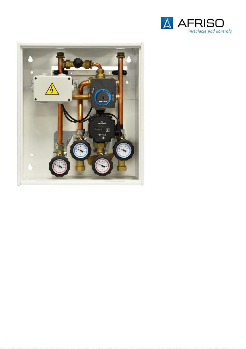
2 PrimoBox ACB 910 mixing unit for condensing boilers
Table of Contents
1Explanations to the installation and operation manual............................................3
1.1 Safety messages and hazard categories .....................................................3
2Information on safety ...............................................................................................3
2.1 Intended use.................................................................................................3
2.2 Quality control...............................................................................................3
2.3 Qualification of personnel.............................................................................4
2.4 Modifications to the product..........................................................................4
2.5 Using additional parts and accessories........................................................4
2.6 Liability..........................................................................................................4
3Product description..................................................................................................5
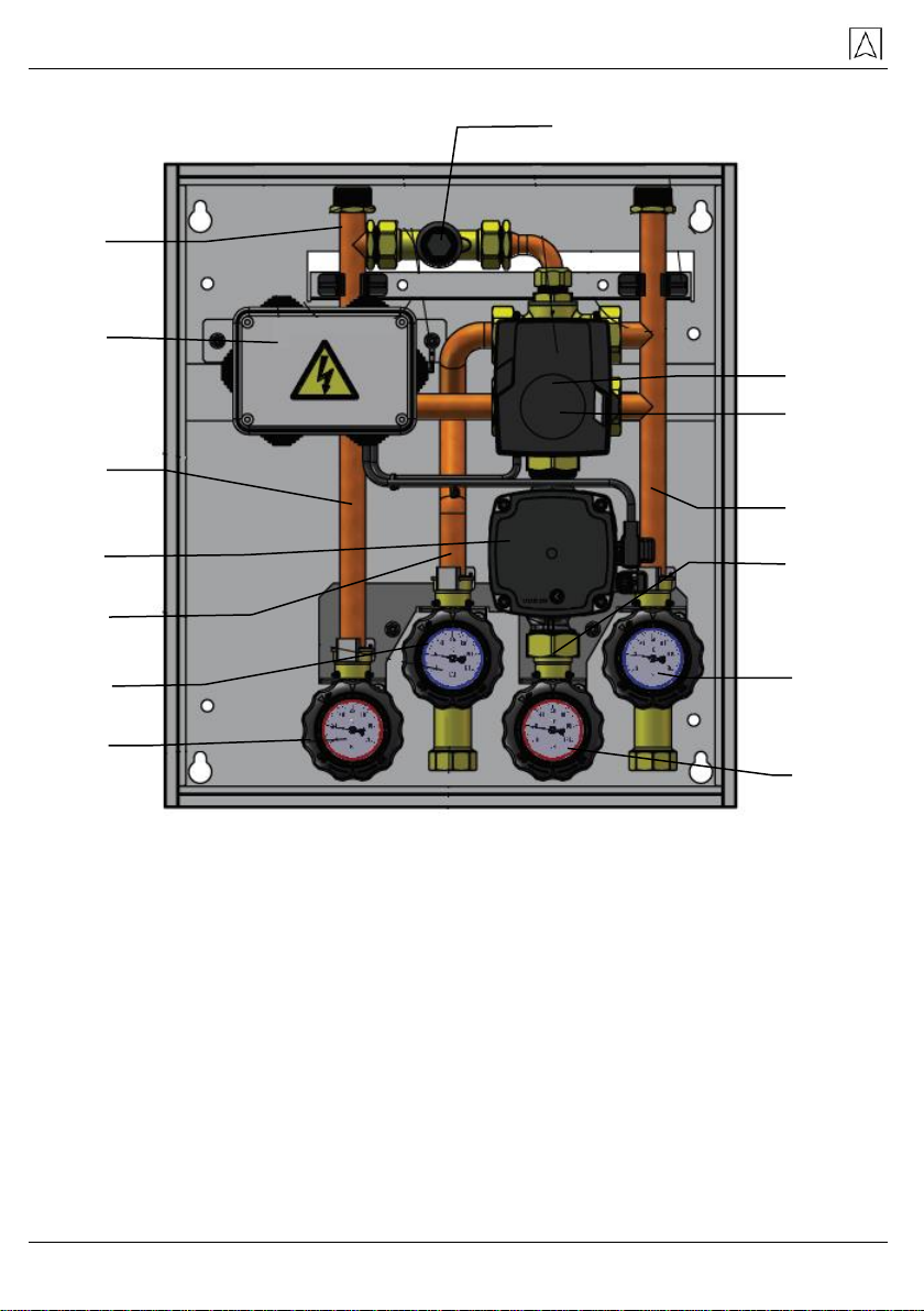
3.1 Construction ................................................................................................6
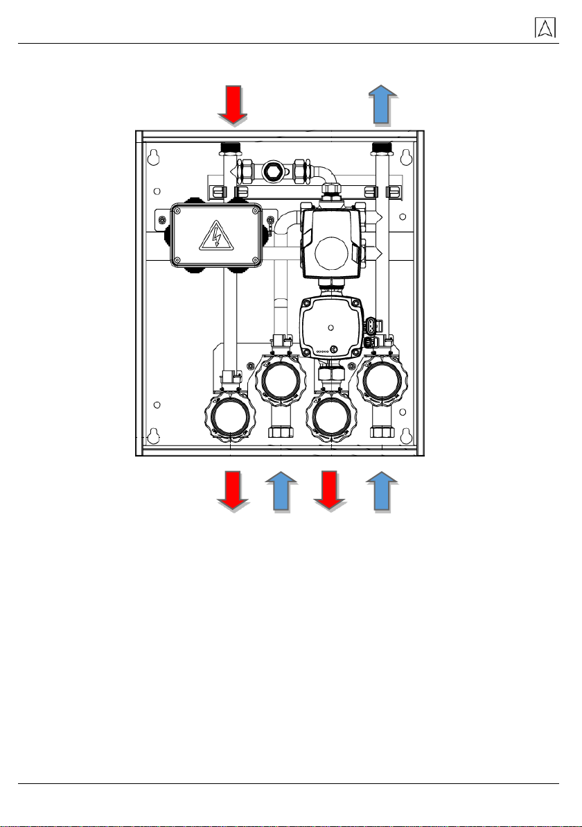
3.2 Operation......................................................................................................7
3.3 Hydraulic diagram of the ACB 910 unit ........................................................9
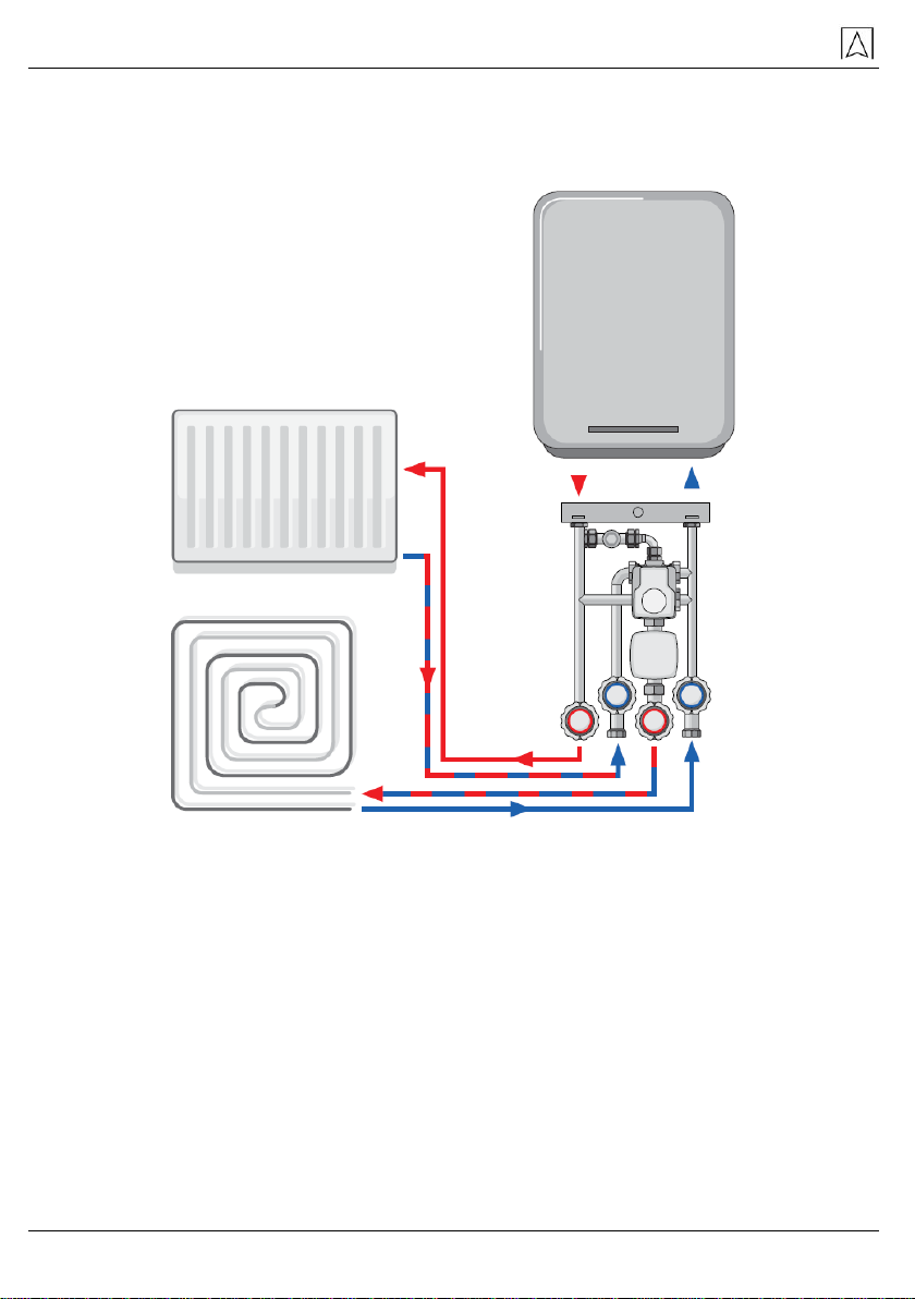
3.4 Application scheme ....................................................................................10
4Specification...........................................................................................................11
4.1 Approvals....................................................................................................11
4.2 Available pressure chart.............................................................................12
5Transport and storage ...........................................................................................12
6Installation and commissioning..............................................................................13
6.1 Wall mounting.............................................................................................13
6.2 Flush mounting...........................................................................................14
6.3 Hydraulic connections ................................................................................14
6.3.1 Connection to the heat source ...................................................................14
6.3.2 Connection of individual heating circuits ....................................................15
(direct circuit and mixing circuit) ............................................................................15
6.4 Differential pressure relief valve DU...........................................................15
6.5 Electrical connections.................................................................................15
6.6 Filling and venting.......................................................................................17
7Assembly of the ARM ProClick actuator................................................................18
8Switching the actuator to manual operation ..........................................................19
9Maintenance ..........................................................................................................19
10 Decommissioning, scrapping.................................................................................20
11 Warranty ................................................................................................................20
12 Copyright................................................................................................................20
13 Customer satisfaction ............................................................................................20
14 Addresses..............................................................................................................20